

- •QoS Overview
- •“Do I Know This Already?” Quiz
- •QoS: Tuning Bandwidth, Delay, Jitter, and Loss Questions
- •Foundation Topics
- •QoS: Tuning Bandwidth, Delay, Jitter, and Loss
- •Bandwidth
- •The clock rate Command Versus the bandwidth Command
- •QoS Tools That Affect Bandwidth
- •Delay
- •Serialization Delay
- •Propagation Delay
- •Queuing Delay
- •Forwarding Delay
- •Shaping Delay
- •Network Delay
- •Delay Summary
- •QoS Tools That Affect Delay
- •Jitter
- •QoS Tools That Affect Jitter
- •Loss
- •QoS Tools That Affect Loss
- •Summary: QoS Characteristics: Bandwidth, Delay, Jitter, and Loss
- •Voice Basics
- •Voice Bandwidth Considerations
- •Voice Delay Considerations
- •Voice Jitter Considerations
- •Voice Loss Considerations
- •Video Basics
- •Video Bandwidth Considerations
- •Video Delay Considerations
- •Video Jitter Considerations
- •Video Loss Considerations
- •Comparing Voice and Video: Summary
- •IP Data Basics
- •Data Bandwidth Considerations
- •Data Delay Considerations
- •Data Jitter Considerations
- •Data Loss Considerations
- •Comparing Voice, Video, and Data: Summary
- •Foundation Summary
- •QoS Tools and Architectures
- •“Do I Know This Already?” Quiz
- •QoS Tools Questions
- •Differentiated Services Questions
- •Integrated Services Questions
- •Foundation Topics
- •Introduction to IOS QoS Tools
- •Queuing
- •Queuing Tools
- •Shaping and Policing
- •Shaping and Policing Tools
- •Congestion Avoidance
- •Congestion-Avoidance Tools
- •Call Admission Control and RSVP
- •CAC Tools
- •Management Tools
- •Summary
- •The Good-Old Common Sense QoS Model
- •GOCS Flow-Based QoS
- •GOCS Class-Based QoS
- •The Differentiated Services QoS Model
- •DiffServ Per-Hop Behaviors
- •The Class Selector PHB and DSCP Values
- •The Assured Forwarding PHB and DSCP Values
- •The Expedited Forwarding PHB and DSCP Values
- •The Integrated Services QoS Model
- •Foundation Summary
- •“Do I Know This Already?” Quiz Questions
- •CAR, PBR, and CB Marking Questions
- •Foundation Topics
- •Marking
- •IP Header QoS Fields: Precedence and DSCP
- •LAN Class of Service (CoS)
- •Other Marking Fields
- •Summary of Marking Fields
- •Class-Based Marking (CB Marking)
- •Network-Based Application Recognition (NBAR)
- •CB Marking show Commands
- •CB Marking Summary
- •Committed Access Rate (CAR)
- •CAR Marking Summary
- •Policy-Based Routing (PBR)
- •PBR Marking Summary
- •VoIP Dial Peer
- •VoIP Dial-Peer Summary
- •Foundation Summary
- •Congestion Management
- •“Do I Know This Already?” Quiz
- •Queuing Concepts Questions
- •WFQ and IP RTP Priority Questions
- •CBWFQ and LLQ Questions
- •Comparing Queuing Options Questions
- •Foundation Topics
- •Queuing Concepts
- •Output Queues, TX Rings, and TX Queues
- •Queuing on Interfaces Versus Subinterfaces and Virtual Circuits (VCs)
- •Summary of Queuing Concepts
- •Queuing Tools
- •FIFO Queuing
- •Priority Queuing
- •Custom Queuing
- •Weighted Fair Queuing (WFQ)
- •WFQ Scheduler: The Net Effect
- •WFQ Scheduling: The Process
- •WFQ Drop Policy, Number of Queues, and Queue Lengths
- •WFQ Summary
- •Class-Based WFQ (CBWFQ)
- •CBWFQ Summary
- •Low Latency Queuing (LLQ)
- •LLQ with More Than One Priority Queue
- •IP RTP Priority
- •Summary of Queuing Tool Features
- •Foundation Summary
- •Conceptual Questions
- •Priority Queuing and Custom Queuing
- •CBWFQ, LLQ, IP RTP Priority
- •Comparing Queuing Tool Options
- •“Do I Know This Already?” Quiz
- •Shaping and Policing Concepts Questions
- •Policing with CAR and CB Policer Questions
- •Shaping with FRTS, GTS, DTS, and CB Shaping
- •Foundation Topics
- •When and Where to Use Shaping and Policing
- •How Shaping Works
- •Where to Shape: Interfaces, Subinterfaces, and VCs
- •How Policing Works
- •CAR Internals
- •CB Policing Internals
- •Policing, but Not Discarding
- •Foundation Summary
- •Shaping and Policing Concepts
- •“Do I Know This Already?” Quiz
- •Congestion-Avoidance Concepts and RED Questions
- •WRED Questions
- •FRED Questions
- •Foundation Topics
- •TCP and UDP Reactions to Packet Loss
- •Tail Drop, Global Synchronization, and TCP Starvation
- •Random Early Detection (RED)
- •Weighted RED (WRED)
- •How WRED Weights Packets
- •WRED and Queuing
- •WRED Summary
- •Flow-Based WRED (FRED)
- •Foundation Summary
- •Congestion-Avoidance Concepts and Random Early Detection (RED)
- •Weighted RED (WRED)
- •Flow-Based WRED (FRED)
- •“Do I Know This Already?” Quiz
- •Compression Questions
- •Link Fragmentation and Interleave Questions
- •Foundation Topics
- •Payload and Header Compression
- •Payload Compression
- •Header Compression
- •Link Fragmentation and Interleaving
- •Multilink PPP LFI
- •Maximum Serialization Delay and Optimum Fragment Sizes
- •Frame Relay LFI Using FRF.12
- •Choosing Fragment Sizes for Frame Relay
- •Fragmentation with More Than One VC on a Single Access Link
- •FRF.11-C and FRF.12 Comparison
- •Foundation Summary
- •Compression Tools
- •LFI Tools
- •“Do I Know This Already?” Quiz
- •Foundation Topics
- •Call Admission Control Overview
- •Call Rerouting Alternatives
- •Bandwidth Engineering
- •CAC Mechanisms
- •CAC Mechanism Evaluation Criteria
- •Local Voice CAC
- •Physical DS0 Limitation
- •Max-Connections
- •Voice over Frame Relay—Voice Bandwidth
- •Trunk Conditioning
- •Local Voice Busyout
- •Measurement-Based Voice CAC
- •Service Assurance Agents
- •SAA Probes Versus Pings
- •SAA Service
- •Calculated Planning Impairment Factor
- •Advanced Voice Busyout
- •PSTN Fallback
- •SAA Probes Used for PSTN Fallback
- •IP Destination Caching
- •SAA Probe Format
- •PSTN Fallback Scalability
- •PSTN Fallback Summary
- •Resource-Based CAC
- •Resource Availability Indication
- •Gateway Calculation of Resources
- •RAI in Service Provider Networks
- •RAI in Enterprise Networks
- •RAI Operation
- •RAI Platform Support
- •Cisco CallManager Resource-Based CAC
- •Location-Based CAC Operation
- •Locations and Regions
- •Calculation of Resources
- •Automatic Alternate Routing
- •Location-Based CAC Summary
- •Gatekeeper Zone Bandwidth
- •Gatekeeper Zone Bandwidth Operation
- •Single-Zone Topology
- •Multizone Topology
- •Zone-per-Gateway Design
- •Gatekeeper in CallManager Networks
- •Zone Bandwidth Calculation
- •Gatekeeper Zone Bandwidth Summary
- •Integrated Services / Resource Reservation Protocol
- •RSVP Levels of Service
- •RSVP Operation
- •RSVP/H.323 Synchronization
- •Bandwidth per Codec
- •Subnet Bandwidth Management
- •Monitoring and Troubleshooting RSVP
- •RSVP CAC Summary
- •Foundation Summary
- •Call Admission Control Concepts
- •Local-Based CAC
- •Measurement-Based CAC
- •Resources-Based CAC
- •“Do I Know This Already?” Quiz
- •QoS Management Tools Questions
- •QoS Design Questions
- •Foundation Topics
- •QoS Management Tools
- •QoS Device Manager
- •QoS Policy Manager
- •Service Assurance Agent
- •Internetwork Performance Monitor
- •Service Management Solution
- •QoS Management Tool Summary
- •QoS Design for the Cisco QoS Exams
- •Four-Step QoS Design Process
- •Step 1: Determine Customer Priorities/QoS Policy
- •Step 2: Characterize the Network
- •Step 3: Implement the Policy
- •Step 4: Monitor the Network
- •QoS Design Guidelines for Voice and Video
- •Voice and Video: Bandwidth, Delay, Jitter, and Loss Requirements
- •Voice and Video QoS Design Recommendations
- •Foundation Summary
- •QoS Management
- •QoS Design
- •“Do I Know This Already?” Quiz
- •Foundation Topics
- •The Need for QoS on the LAN
- •Layer 2 Queues
- •Drop Thresholds
- •Trust Boundries
- •Cisco Catalyst Switch QoS Features
- •Catalyst 6500 QoS Features
- •Supervisor and Switching Engine
- •Policy Feature Card
- •Ethernet Interfaces
- •QoS Flow on the Catalyst 6500
- •Ingress Queue Scheduling
- •Layer 2 Switching Engine QoS Frame Flow
- •Layer 3 Switching Engine QoS Packet Flow
- •Egress Queue Scheduling
- •Catalyst 6500 QoS Summary
- •Cisco Catalyst 4500/4000 QoS Features
- •Supervisor Engine I and II
- •Supervisor Engine III and IV
- •Cisco Catalyst 3550 QoS Features
- •Cisco Catalyst 3524 QoS Features
- •CoS-to-Egress Queue Mapping for the Catalyst OS Switch
- •Layer-2-to-Layer 3 Mapping
- •Connecting a Catalyst OS Switch to WAN Segments
- •Displaying QoS Settings for the Catalyst OS Switch
- •Enabling QoS for the Catalyst IOS Switch
- •Enabling Priority Queuing for the Catalyst IOS Switch
- •CoS-to-Egress Queue Mapping for the Catalyst IOS Switch
- •Layer 2-to-Layer 3 Mapping
- •Connecting a Catalyst IOS Switch to Distribution Switches or WAN Segments
- •Displaying QoS Settings for the Catalyst IOS Switch
- •Foundation Summary
- •LAN QoS Concepts
- •Catalyst 6500 Series of Switches
- •Catalyst 4500/4000 Series of Switches
- •Catalyst 3550/3524 Series of Switches
- •QoS: Tuning Bandwidth, Delay, Jitter, and Loss
- •QoS Tools
- •Differentiated Services
- •Integrated Services
- •CAR, PBR, and CB Marking
- •Queuing Concepts
- •WFQ and IP RTP Priority
- •CBWFQ and LLQ
- •Comparing Queuing Options
- •Conceptual Questions
- •Priority Queuing and Custom Queuing
- •CBWFQ, LLQ, IP RTP Priority
- •Comparing Queuing Tool Options
- •Shaping and Policing Concepts
- •Policing with CAR and CB Policer
- •Shaping with FRTS, GTS, DTS, and CB Shaping
- •Shaping and Policing Concepts
- •Congestion-Avoidance Concepts and RED
- •WRED
- •FRED
- •Congestion-Avoidance Concepts and Random Early Detection (RED)
- •Weighted RED (WRED)
- •Flow-Based WRED (FRED)
- •Compression
- •Link Fragmentation and Interleave
- •Compression Tools
- •LFI Tools
- •Call Admission Control Concepts
- •Local-Based CAC
- •Measurement-Based CAC
- •Resources-Based CAC
- •QoS Management Tools
- •QoS Design
- •QoS Management
- •QoS Design
- •LAN QoS Concepts
- •Catalyst 6500 Series of Switches
- •Catalyst 4500/4000 Series of Switches
- •Catalyst 3550/3524 Series of Switches
- •Foundation Topics
- •QPPB Route Marking: Step 1
- •QPPB Per-Packet Marking: Step 2
- •QPPB: The Hidden Details
- •QPPB Summary
- •Flow-Based dWFQ
- •ToS-Based dWFQ
- •Distributed QoS Group–Based WFQ
- •Summary: dWFQ Options

Resource-Based CAC 585
Resource Availability Indication
To allow gatekeepers to make intelligent call routing decisions, the terminating gateway uses resource availability indication (RAI) to report resource availability to the gatekeeper. Resources monitored by the terminating gateway include DS0 channels and DSP channels. When a monitored resource falls below a configurable threshold, the gateway sends an RAI message to the gatekeeper indicating that the gateway is almost out of resources. When the
available resources then cross above another configurable threshold, the gateway sends an RAI message indicating that the resource depletion condition no longer exists. The gatekeeper never has knowledge of the individual resources or the type of resources that the gateway considers. The RAI message is a simple yes or no toggle indication sent by the terminating gateway to control whether the gatekeeper should allow subsequent voice calls to be routed to the terminating gateway. The gatekeeper responds with a resource availability confirmation (RAC) upon receiving an RAI message to acknowledge its reception.
As a CAC mechanism, RAI is unique in its capability to provide information on the terminating POTS connection. Other mechanisms discussed in this chapter enable CAC decisions based on local information at the originating gateway and on the condition of the IP cloud between the originating gateway and terminating gateways. No other CAC mechanism has the capability to consider the availability of resources to terminate the POTS call at the terminating gateway.
Another difference is that with RAI the CAC decision is controlled by the terminating gateway. In all the other methods, the CAC decision is controlled by the originating gateway or by the gatekeeper.
RAI was included in Cisco IOS Software Release 12.0(5)T on the Cisco AS5300 Gateway, and Cisco IOS Software Release 12.1(1)T for other gateways in H323v2.
Gateway Calculation of Resources
The calculation to reach the CAC decision is performed by the terminating gateway. Different gateway platforms may use different algorithms. The H.323 standard does not prescribe the calculation or the resources to include in the calculation. It merely specifies the RAI message format and the need for the gatekeeper to discontinue routing calls to the terminating gateway in the event that the gateway has insufficient available resources for the additional call, and the gateway will inform the gatekeeper to resume routing calls when resources become free.
Calculating utilization first takes into account the number of accessible channels on the target device. Accessible channels are either active or idle voice channels on the device that are used to carry voice conversations. Disabled channels are not counted as accessible channels.
The following formula is used to determine accessible channels:
Accessible channels = Channels being used + Free channels

586 Chapter 8: Call Admission Control and QoS Signaling
When the number of accessible channels is known, the utilization can be calculated from the following formula:
Utilization = Channels being used
---------------------------------------------------------------------------------
Accessible channels
Suppose, for instance, that you have four T1 CAS circuits. Two of the T1 CAS circuits are used for incoming calls, and the remaining two T1 CAS circuits are used for outgoing calls. You have busied out 46 time slots of the outgoing time slots, and you have one call on one of the outgoing time slots. You will have the following:
•
•
•
•
•
Total voice channels = 96
Outgoing total voice channels = 48
Disabled voice channels = 46
Voice channels being used = 1
Free voice channels = 1
The outgoing accessible channels in this situation are as follows:
1 (voice channels being used) + 1 (free voice channels)= 2
The DS0 utilization for this device is as follows:
Channels being used
Utilization = -------------------------------------------------
Accessible channels
or
1
50% = ----------------
( 1 + 1)
The utilization for the outgoing channels is equal to 50 percent. If the configured high threshold is 90 percent, the gateway will still accept calls. Only DS0s reachable through a VoIP dial peer are included in the calculation.
The preceding calculation took the DS0 resources into consideration. Remember that the DSP resources are monitored and calculated in the same manner. The terminating gateway sends an RAI message in the event that either the DS0 or DSP resources reach the low or high threshold.
RAI in Service Provider Networks
RAI is an indispensable feature in SP networks that provide VoIP calling services such as debit and credit card calling and VoIP long-distance phone service. Figure 8-17 shows the general structure of these networks.
Resource-Based CAC 587
Figure 8-17 Service Provider VoIP Network Topology
Directory-GK
HSRP
Directory-GK
HSRP
Service Provider VoIP
Backbone
|
Alternate |
West GK |
West GK |
|
HSRP |
|
Alternate |
East GK |
East GK |
|
HSRP |
PSTN |
PSTN |
Around the world there are points of presence (POPs) where racks of gateways, such as Cisco AS5300 access servers, connect to the PSTN with T1/E1 trunks. The call routing is managed through several levels of gatekeepers as shown in Figure 8-17. Call volume is high, and these gateways handle voice traffic only (no data traffic other than minimal IP routing and network management traffic).
When a customer on the West Coast dials a number residing on the East Coast PSTN, the East Coast gatekeeper must select an East Coast gateway that has an available PSTN trunk to terminate the call. If an East Cost gateway cannot be found, the customer’s call fails. In the event of a failed call, the originating gateway must retry the call or the customer must redial the call. In either case, there is no guarantee that the same out-of-capacity terminating gateway will not be selected again.
This scenario is inefficient and provides poor customer service. It is important that calls are not routed by the gatekeeper to a terminating gatekeeper that cannot terminate the call due to the lack of PSTN trunk capacity.
In general, calls are load balanced by the gatekeeper across the terminating gateways in its zone. But the gateways could have different levels of T1/E1 capacity and by load balancing across the gateways one gateway could become shorter on resources than another. It is in this situation that RAI is imperative. The overloaded terminating gateway has the capability to initiate an indication to the gatekeeper that it is too busy to take more calls.

588 Chapter 8: Call Admission Control and QoS Signaling
RAI in Enterprise Networks
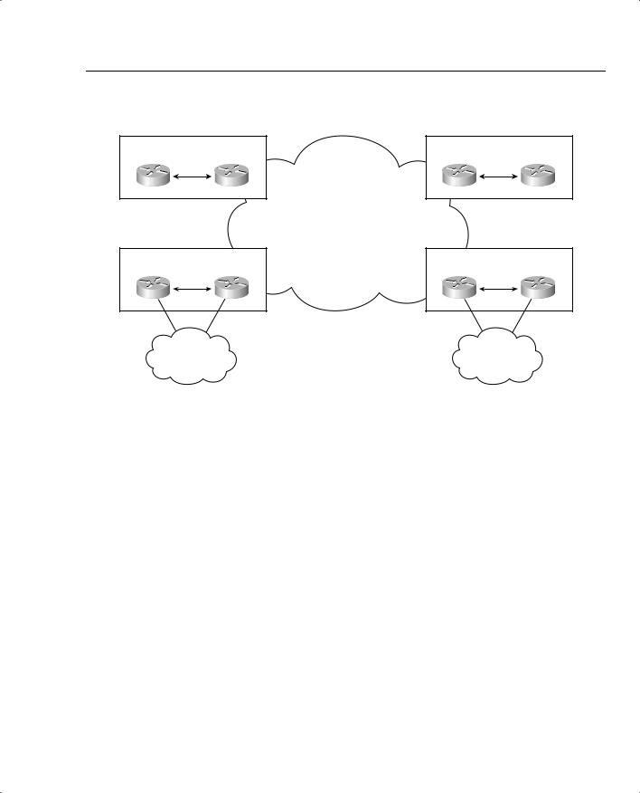
RAI is generally less applicable in enterprise networks than in SP networks because there is often only one gateway at each site, as shown in Figure 8-18. This is almost always true for the typical hub-and-spoke enterprise network. Even at the large sites, there may be multiple T1/E1 trunks to the attached PBX, but there are seldom multiple gateways.
Figure 8-18 Enterprise VoIP Network Topology
R1 |
Gatekeeper |
R4 |
|
||
Site 1 |
|
Site 4 |
|
|
IP Network
R2
Site 2
|
R3 |
|
SW3 |
IP |
IP |
Site 3 |
|
R5
Site 5
|
R6 |
|
IP |
IP |
SW6 |
|
IP |
IP |
IP |
|
Site 6 |
If a single gateway is used to terminate a call, where the called user resides on a specific PBX and is reachable only through a specific gateway in the network, RAI does not provide additional network intelligence. With no alternate gateway to handle excess calls, a call will always