236 Chapter 4: Congestion Management
Foundation Topics
Queuing has an impact on all four QoS characteristics directly—bandwidth, delay, jitter, and packet loss. Many people, upon hearing the term “QoS,” immediately think of queuing, but QoS includes many more concepts and features than just queuing. Queuing is certainly the most often deployed and most important QoS tool.
This chapter begins by explaining the core concepts about queuing. Following that, each queuing tool is covered, including additional concepts specific to that tool, configuration, monitoring, and troubleshooting.
Queuing Concepts
Most people already understand many of the concepts behind queuing. First, this section explains the basics and defines a few terms. Afterward, some of the IOS-specific details are covered.
IOS stores packets in memory while processing the packet. When a router has completed all the required work except actually sending the packet, if the outgoing interface is currently busy, the router just keeps the packet in memory waiting on the interface to become available. To manage the set of packets sitting around in memory waiting to exit an interface, IOS creates a queue. A queue just organizes the packets waiting to exit an interface; the queue itself is nothing more than a series of pointers to the memory buffers that hold the individual packets that are waiting to exit the interface.
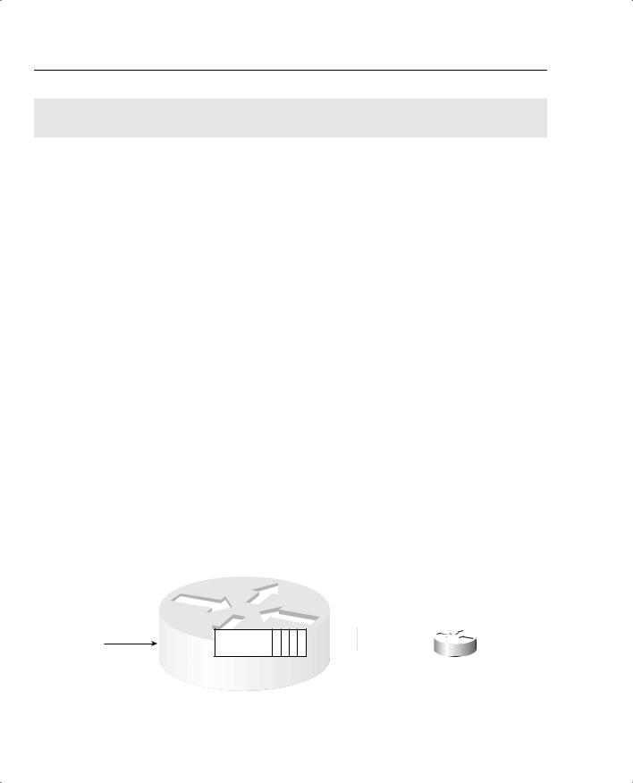
The most basic queuing scheme uses a single queue, with first-in, first-out (FIFO) scheduling. What does that mean? Well, when the IOS decides to take the next packet from the queue, of those packets still in the queue, it takes the one that arrived earlier than all the other packets in the queue. Figure 4-1 shows a router, with an interface using a single FIFO queue.
Figure 4-1 Single FIFO Queue
4 X 1500
Byte Packets Is there room in the queue?
R1
FIFO Output Queue
4 3 2 1 

 R2
R2
Queuing Concepts 237
Although a single FIFO queue seems to provide no QoS features at all, it actually does affect drop, delay, and jitter. Because there is only one queue, the router need not classify traffic to place it into different queues. Because there is only one queue, the router need not worry about how to decide from which queue it should take the next packet—there is only one choice. And because this single queue uses FIFO logic, the router need not reorder the packets inside the queue.
However, the size of the output queue affects delay, jitter, and loss. Because the queue has a finite size, it may fill. If it fills, and another packet needs to be added to the queue, tail drop would cause the packet to be dropped. One solution to the drops would be to lengthen the queue, which decreases the likelihood of tail drop. With a longer queue, however, the average delay increases, because packets may be enqueued behind a larger number of other packets. In most cases when the average delay increases, the average jitter increases as well. The following list summarizes the key concepts regarding queue length:
•With a longer queue length, the chance of tail drop decreases as compared with a shorter queue, but the average delay increases, with the average jitter typically increasing as well.
•With a shorter queue length, the chance of tail drop increases as compared with a longer queue, but the average delay decreases, with the average jitter typically decreasing as well.
•If the congestion is sustained such that the offered load of bytes trying to exit an interface exceeds the interface speed for long periods, drops will be just as likely whether the queue is short or long.
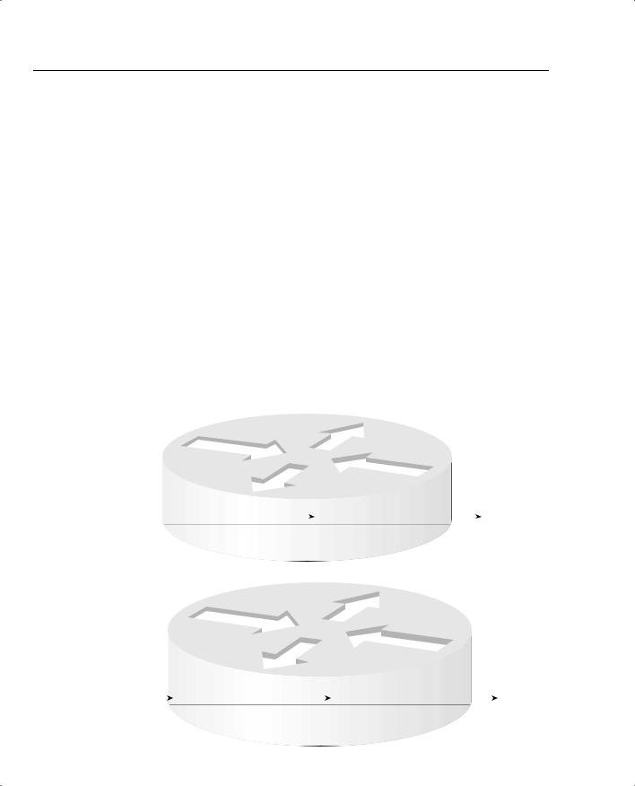
To appreciate most queuing concepts, you need to consider a queuing system with at least two queues. Consider Figure 4-2, which illustrates two FIFO output queues.
Figure 4-2 Dual FIFO Output Queues
|
|
|
|
|
|
R1 |
|
|
|
1 |
|
|
|
Output Queue 1 |
|
|
|
|
|
Into which queue |
|
|
3 |
2 |
1 |
|
|
|
4 |
|
4 X 1500 |
|
should I place |
|
|
|
|
|
|
|
|
|
|
|
|
|
|
|
|
|
|
|
each packet? |
|
|
|
|
|
|
|
|
|
|
|
Byte Packets |
|
|
|
|
|
|
|
|
|
|
From which queue do I |
|
|
|
|
|
|
|
|
|
|
|
|
|
|
|
|
|
|
|
|
|
|
|
|
|
|
|
|
|
|
|
Is there room |
|
|
Output Queue 2 |
|
|
|
take the next packet? |
R2 |
|
|
in the queue? |
|
|
|
|
|
4 |
|
|
|
|
|
|
2 |
|
|
|
|
|
|
|
|
|
|
|
|
|
|
|
|
|
|
|
|
|
|
|
|
|
|
|
|
|
|
|
|
|
|
|
|
|
|
|
|
|
|
3Should I reorder packet inside a single queue?
Figure 4-2 illustrates the questions that are answered by the queuing tool. Step 1, the classification step, works like classification and marking tools, except the resulting action is to place a packet in a queue, as opposed to marking a packet. So, at step 1, the packet header is examined,
238 Chapter 4: Congestion Management
and depending on the matched values, the packet is placed into the appropriate queue. Before placing the packet in the queue, the router must make sure that space is available, as shown in step 2 in Figure 4-2. If no space is available, the packet is dropped. Inside each queue, the packets can be reordered (step 3): in this example, however, each queue uses FIFO logic inside each queue, so the packets would never be reordered inside the queue. Finally, the queuing system must choose to take the next packet for transmission from either Queue 1 or Queue 2 (step 4). The scheduler makes the decision at step 4.
Although the classification portion of each queuing tool is relatively obvious, consider two related points when thinking about classification by a queuing tool. First, with a QoS strategy that causes classification and marking to occur near the ingress edge of the network, the queuing tool may enqueue packets that have already been marked. So, the queuing tool can classify based on these marked fields, which was the whole point in marking them in the first place! Second, for each category of traffic for which you want to provide different queuing treatment, you need a different queue. For instance, you may want to classify traffic into six classes for queuing, so each class can get different treatment in a different queue. If the queuing tool only supports four different queues, you may need to consider a different queuing tool to support your QoS policy.
Inside each queue, the queuing methods use FIFO Queuing. The interesting logic for queuing occurs after the packets have been enqueued, when the router decides from which queue to take the next packet. Queue scheduling describes the process of the device, in this case a router, choosing which queue to service next. This process is also called a service algorithm, or a queue service algorithm. The scheduler may reserve amounts of bandwidth, or a percentage of link bandwidth, for a particular queue. The scheduler may always service one queue first, which means the packets in that queue will experience very low delay and jitter.
For the exams, you need to know what each queuing tool’s scheduler accomplishes; for some tools, however, you also need to know the internals of how the scheduler actually works.
NOTE Cisco leads the industry in making details about their products public (being the first large networking vendor to publish bug reports, for instance). However, Cisco must also protect their intellectual assets. So, for some of the newer queuing tools, Cisco has not yet published every detail about how the scheduling algorithm works. For some of the older queuing tools, the details are published. Frankly, the details of how the scheduling code works inside IOS might be interesting, but it is not really necessary for a deep understanding of what a queuing tool does. For the QoS exams, you need to know what each queuing tool’s scheduler accomplishes; for some tools, however, you also need to know the internals of how the scheduler actually works. When necessary, this book gives you plenty of details about the internal scheduling algorithms to help prepare you for the exams.
Queuing Concepts 239
A final comment about the core concepts of queuing: The size of each packet does not affect the length of the queue, or how many packets it can hold. A queue of length 10 holds ten 1500byte packets as easily as it holds ten 64-byte packets. Queues actually do not hold the packets themselves, but instead just hold pointers to the packets, whose contents are held in buffers.
Table 4-2 summarizes the key concepts of queuing. This table is used to compare the various queuing tools in the “Queuing Tools” section of this chapter.
Table 4-2 Key Concepts When Comparing Queuing Tools
|
|
QoS |
|
|
Characteristic |
Feature |
Definition |
Affected |
|
|
|
Classification |
The capability to examine packets to determine into |
None |
|
which queue the packet should be placed. Many |
|
|
options are available. |
|
|
|
|
Drop policy |
When the queue has been determined, the drop policy |
Loss |
|
defines the rules by which the router chooses to drop |
|
|
the packet. Tail drop, modified tail drop, WRED |
|
|
(Weighted Random Early Detect), and FRED (Flow- |
|
|
Based Random Early Detect) are the main options. |
|
|
|
|
Scheduling inside a single |
Inside a single queue, packets can be reordered. In |
Bandwidth, |
queue |
most cases, however, FIFO logic is used for packets |
delay, jitter, and |
|
inside each queue. |
loss |
|
|
|
Scheduling between |
The logic that defines how queuing chooses the next |
Bandwidth, |
different queues |
packet to take from the output queues and place it in |
delay, jitter, and |
|
the TX Queue (Transmit Queue). |
loss |
|
|
|
Maximum number of |
The maximum number of different queues the queuing |
None |
queues |
tools support, which in turn implies the maximum |
|
|
number of traffic classifications that can be treated |
|
|
differently by the queuing method. |
|
|
|
|
Maximum queue length |
The maximum number of packets in a single queue. |
Loss, delay |
|
|
|
Output Queues, TX Rings, and TX Queues
NOTE This section covers the concepts behind TX Rings and TX Queues. Interestingly, the DQOS exam 9E0-601 does not mention these topics at all, but the QoS exam does. For a true understanding of queuing inside IOS, however, you must understand these concepts. Therefore, for you DQOS exam takers, you might choose to just focus on the concepts about TX Queues and TX Rings, and not worry about memorization. As always, check the websites listed in the Introduction for any news about changes to the exams.
240 Chapter 4: Congestion Management
Packets do not move directly from an interface’s output queue to being transmitted out of an interface. Instead, the router moves the packet from the interface output queue to another small FIFO queue on each interface. Cisco calls this separate, final queue either the Transmit Queue (TX Queue) or Transmit Ring (TX Ring), depending on the model of the router. Regardless of which name is used, for the purposes of this book, the TX Queue and TX Ring concepts can be considered to be equivalent. I will use the two terms synonymously.
The TX Ring’s objective is to drive the link utilization to 100 percent when packets are waiting to exit an interface. The TX Queue holds outgoing packets so that the interface does not have to rely on the general-purpose processor in the router in order to start sending the next packet. The TX Queue can be accessed directly by the application-specific integrated circuits (ASICs) associated with an interface, so even if the general processor is busy, the interface can begin sending the next packet without waiting for the router CPU. Because the most constrained resource in a router is typically the bandwidth on the attached interfaces, particularly on WAN interfaces, the router hopes to always be able to send the next packet immediately when the interface finishes sending the last packet. The TX Queue provides a key component to reach that goal.
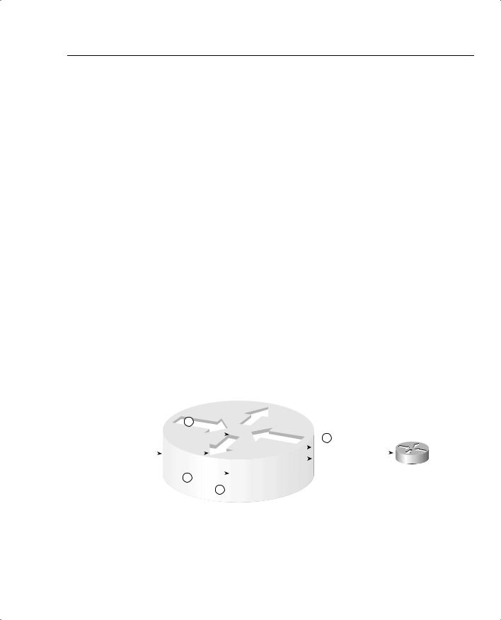
However, the existence of the TX Queue does impact queuing to some extent. Figure 4-3 depicts the TX Queue, along with a single FIFO Queuing output queue.
Figure 4-3 Single FIFO Output Queue, with a Single TX Queue
R1 — Serial 0
4 Packets |
|
|
TX Queue, Length 4, Not Controlled |
|
|
by Queuing Tool |
Arriving |
Output Queue: Not Needed in This Case |
|
|
|
|
|
Packet 4 |
Packet 3 |
Packet 2 |
Packet 1 |
|
when TX |
|
|
|
|
|
|
Queue Is |
|
|
|
|
|
|
|
|
|
|
|
|
|
|
Empty |
|
|
|
|
|
|
|
R1 — Serial 0
Packets Arriving |
|
|
|
|
|
|
|
TX Queue, Length 4, Not Controlled |
|
Output Queue: Controlled by Queuing Tool |
by Queuing Tool |
|
when TX Queue Is |
|
|
|
|
|
|
|
|
|
|
|
|
|
|
Full, and Some |
|
|
|
|
Packet 7 |
Packet 6 |
Packet 5 |
|
|
Packet 4 |
Packet 3 |
Packet 2 |
Packet 1 |
|
|
|
|
|
Packets in Software |
|
|
|
|
|
|
|
|
|
|
|
|
|
|
|
|
|
|
|
|
|
|
|
|
|
|
Queue |
|
|
|
|
|
|
|
|
|
|
|
|
|
Queuing Concepts 241
Two different examples are outlined in Figure 4-3. In the top part of the figure, the scenario begins with no packets in the output queue, and no packets in the TX Queue. Then, four packets arrive. With a TX Queue with room for four packets, all four packets are placed into the TX Queue.
In the second example, any new packets that arrive will be placed into the software queue. Assuming that the software queue and the TX Queue were empty before the seven packets shown in the figure arrived, the first four packets would have been placed in the TX queue, and the last three in the software queue. So, any new packets will be placed at the end of the software queue.
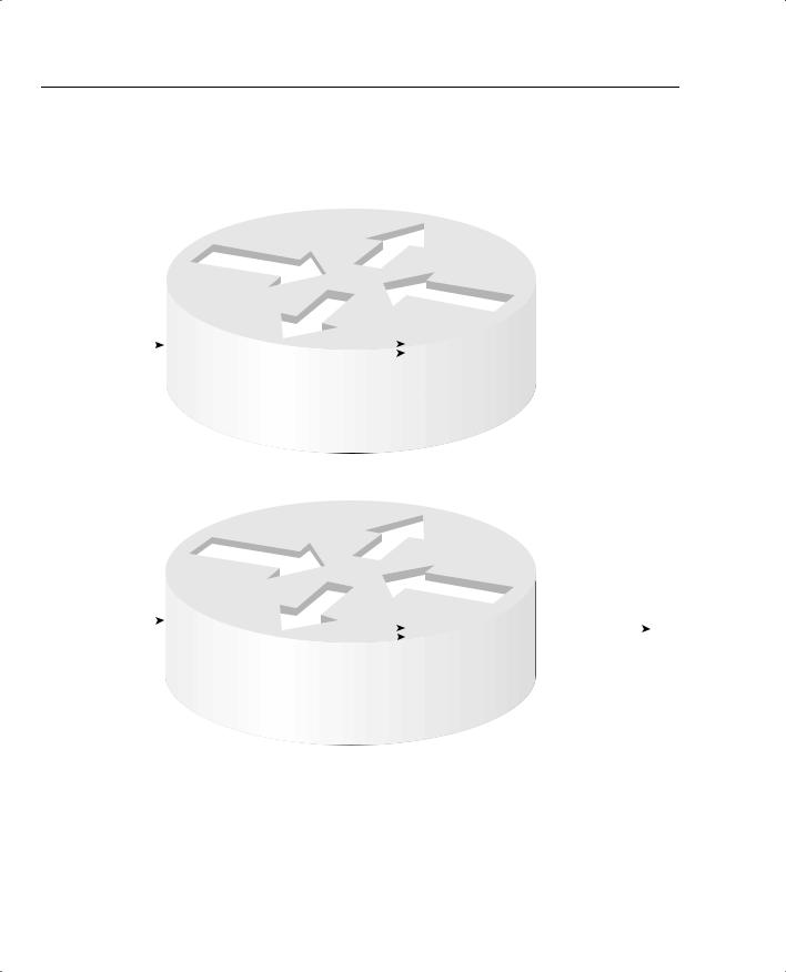
All the queuing tools in IOS create and manage interface output queues, not interface TX Queues or TX Rings. Each interface uses one TX Queue (or TX Ring), and the TX Queue is a FIFO queue, unaffected by the queuing configuration on the interface. In Figure 4-3, the packets are sent in the same order that they would have been sent if the TX Queue did not exist. In some cases, however, the TX Queue impacts the results of the queuing scheduler. For instance, consider Figure 4-4, where queuing is configured with two queues. In this scenario, seven packets arrive, numbered in the order in which they arrive. The output queuing configuration specifies that the first two packets (1 and 2) should be placed into Queue 2, and the next four packets (numbered 3 through 6) should be placed into Queue 1.
Many people assume that the router behaves as shown in the top part of Figure 4-4, with the queuing scheduler determining the order in which packets exit the interface. In reality, IOS behaves as shown in the bottom half of Figure 4-4. In the top half of the figure, if all six packets were to arrive instantaneously, all six packets would be placed into the appropriate output queue. If this particular queuing tool’s scheduler always serviced packets from Queue 1, and only serviced Queue 2 if Queue 1 was empty, the packets will leave in a different order than they arrived. In fact, packets 3 through 6 would exit in order, and then packets 1 and 2 would be sent. Ultimately, the order would just depend on the logic of the scheduling part of the queuing tool.
In this particular example, however, the packets would actually exit the interface in the same order that the packets were received because of the existence of the TX Queue. As mentioned earlier, when the router identifies the output interface for a packet, it checks the TX Queue for that interface. If space is available, the packet is placed in the TX Queue, and no output queuing is performed for that packet. In the example, because the scenario assumes that no other packets were waiting to exit R1’s S0/0 interface before these six packets arrive, the first two packets are placed in the TX Queue. When packet 3 arrives, S0/0’s TX Queue is full, so packets 3 through 6 are placed into an interface output queue, based on the queuing configuration for R1’s S0/0 interface. The queuing classification logic places packets 3 through 6 into Queue 1. The router drains the packets in order from the TX Queue, and moves packets 3, 4, 5, and 6, in order, from Queue 1 into the TX Queue. The actual order that the packets exit S0 is the same order as they arrived.
242 Chapter 4: Congestion Management
Figure 4-4 Output Queues, with Scheduler Always Servicing Queue 1 Rather Than Queue 2 When Packets Are in Queue 1
Assumed Behavior if
No TX Queue
R1 — Serial 0
Output Queue 1 — Preferred Queue
6 Packets: |
|
Packet 6 |
Packet 5 |
Packet 4 |
Packet 3 |
|
|
Scheduler Would Take |
First 2 to |
|
|
|
|
|
|
|
|
|
|
Packets 3-6 from Queue 1 |
Queue 2, |
|
|
|
|
|
|
|
|
|
|
|
|
|
|
|
|
Before Packets 1-2 from |
Next 4 to |
|
|
|
|
|
|
|
|
|
|
|
|
|
|
Queue 2 |
Queue 1 |
|
|
|
Packet 2 |
Packet 1 |
|
|
|
|
|
|
|
|
|
|
|
|
|
|
|
|
|
|
Output Queue 2
Actual Behavior with TX Queue
|
|
|
R1 — Serial0 |
|
|
|
|
|
|
|
6 Packets: |
Output Queue 1 |
|
|
|
|
|
|
|
First 2 to |
Packet 6 |
Packet 5 |
Packet 4 |
Packet 3 |
|
|
|
TX Queue, Length 2 |
|
|
|
|
|
|
|
Queue 2, |
|
|
|
|
|
|
|
|
|
|
Packet 2 |
Packet 1 |
|
|
|
|
|
|
|
|
|
|
|
Next 4 to |
|
|
|
|
|
|
|
|
|
|
|
|
|
|
|
|
|
|
|
|
Queue 1 |
|
|
|
|
|
|
|
Packets Exit in Order |
|
|
|
|
|
|
|
|
|
|
|
|
|
|
|
|
|
|
|
|
|
|
They Arrived |
|
|
|
|
|
|
Output Queue 2 |
|
IOS automatically attempts to minimize the impact of the TX Queue to the IOS queuing tools. The IOS maintains the original goal of always having a packet in the TX Queue, available for the interface to immediately send when the interface completes sending the previous packet.
When any form of output queuing tool is enabled on an interface, IOS reduces the size of the TX Queue to a very small value (typically 2). The smaller the value, the less impact the TX Queue has on the effects of the queuing method.

Queuing Concepts 243
In some cases, you may want to change the setting for the size of the TX Queue or TX Ring. You may also want to know the current setting. Example 4-1 lists several commands that enable you to examine the size of the TX Queue, and change the size.
Example 4-1 TX Queue Length: Finding the Length, and Changing the Length
R3#show controllers serial 0/0 |
|
|
Interface Serial0/0 |
|
|
|
Hardware is PowerQUICC |
MPC860 |
|
|
DCE V.35, clock rate 1300000 |
|
|
idb at 0x8108F318, driver data structure at 0x81096D8C |
SCC Registers: |
|
|
|
General [GSMR]=0x2:0x00000030, Protocol-specific [PSMR]=0x8 |
Events [SCCE]=0x0000, Mask [SCCM]=0x001F, |
Status [SCCS]=0x06 |
Transmit on Demand [TODR]=0x0, Data Sync [DSR]=0x7E7E |
Interrupt Registers: |
|
|
|
Config |
[CICR]=0x00367F80, Pending [CIPR]=0x00008000 |
Mask |
[CIMR]=0x40204000, In-srv [CISR]=0x00000000 |
Command register [CR]=0x600 |
|
|
Port A [PADIR]=0x1100, |
[PAPAR]=0xFFFF |
|
|
|
[PAODR]=0x0000, |
[PADAT]=0xEFFF |
|
|
Port B [PBDIR]=0x09C0F, [PBPAR]=0x0800E |
|
|
|
[PBODR]=0x0000E, [PBDAT]=0x3E77D |
|
|
Port C [PCDIR]=0x00C, [PCPAR]=0x000 |
|
|
|
[PCSO]=0xC20, |
[PCDAT]=0xFC0, [PCINT]=0x00F |
Receive Ring |
|
|
|
|
rmd(68012830): status 9000 length |
1F |
address 3D3FC84 |
|
rmd(68012838): status 9000 length |
42 |
address 3D41D04 |
|
rmd(68012840): status 9000 length |
F address 3D43D84 |
|
rmd(68012848): status 9000 length |
42 |
address 3D43084 |
|
rmd(68012850): status 9000 length |
42 |
address 3D3E904 |
|
rmd(68012858): status 9000 length |
157 address 3D43704 |
Transmit Ring |
|
|
|
|
tmd(680128B0): status 5C00 length |
40 |
address 3C01114 |
|
tmd(680128B8): status 5C00 length |
D address 3C00FD4 |
|
tmd(680128C0): status 5C00 length |
40 |
address 3C00FD4 |
|
tmd(680128C8): status 5C00 length |
D address 3C00E94 |
|
tmd(680128D0): status 5C00 length |
11A address 3D6E394 |
|
tmd(680128D8): status 5C00 length |
40 |
address 3C019D4 |
|
tmd(680128E0): status 5C00 length |
40 |
address 3C01ED4 |
|
tmd(680128E8): status 5C00 length |
D address 3D58BD4 |
|
tmd(680128F0): status 5C00 length |
40 |
address 3D58954 |
|
tmd(680128F8): status 5C00 length |
40 |
address 3D59214 |
|
tmd(68012900): status 5C00 length |
D address 3D59494 |
|
tmd(68012908): status 5C00 length |
40 |
address 3D59AD4 |
|
tmd(68012910): status 5C00 length |
40 |
address 3C00214 |
|
tmd(68012918): status 5C00 length |
D address 3C01C54 |
|
tmd(68012920): status 5C00 length |
40 |
address 3C005D4 |
|
tmd(68012928): status 7C00 length |
40 |
address 3C00714 |
tx_limited=0(16)
244 Chapter 4: Congestion Management
Example 4-1 TX Queue Length: Finding the Length, and Changing the Length (Continued)
SCC GENERAL PARAMETER RAM (at 0x68013C00)
Rx BD Base [RBASE]=0x2830, Fn Code [RFCR]=0x18
Tx BD Base [TBASE]=0x28B0, Fn Code [TFCR]=0x18
Max Rx Buff Len [MRBLR]=1548
Rx State [RSTATE]=0x18008440, BD Ptr [RBPTR]=0x2840
Tx State [TSTATE]=0x18000548, BD Ptr [TBPTR]=0x28C8
SCC HDLC PARAMETER RAM (at 0x68013C38)
CRC Preset [C_PRES]=0xFFFF, Mask [C_MASK]=0xF0B8
Errors: CRC [CRCEC]=0, Aborts [ABTSC]=0, Discards [DISFC]=0
Nonmatch Addr Cntr [NMARC]=0
Retry Count [RETRC]=0
Max Frame Length [MFLR]=1608
Rx Int Threshold [RFTHR]=0, Frame Cnt [RFCNT]=65454
User-defined Address 0000/0000/0000/0000
User-defined Address Mask 0x0000
buffer size 1524
PowerQUICC SCC specific errors:
0 input aborts on receiving flag sequence
0 throttles, 0 enables
0overruns
0transmitter underruns
0transmitter CTS losts
0aborted short frames
!!!!!!!!!!!!!!!!!!!!!!!!!!!!!!!!!!!!!!!!!!!!!!!!!!!!!!!!!!!!!!!!!
R3#conf t
Enter configuration commands, one per line. End with CNTL/Z. R3(config)#int s 0/0
R3(config-if)#priority-group 1
R3(config-if)#^Z
!!!!!!!!!!!!!!!!!!!!!!!!!!!!!!!!!!!!!!!!!!!!!!!!!!!!!!!!!!!!!!!!!!
R3#show controllers serial 0/0
01:03:09: %SYS-5-CONFIG_I: Configured from console by console Interface Serial0/0
!!!!! Lines omitted to save space tx_limited=1(2)
!!!!! Lines omitted to save space
!!!!!!!!!!!!!!!!!!!!!!!!!!!!!!!!!!!!!!!!!!!!!!!!!!!!!!!!!!!!!!!!!!
R3#conf t
Enter configuration commands, one per line. End with CNTL/Z. R3(config)#int s 0/0
R3(config-if)#no priority-group 1
R3(config-if)#tx-ring-limit 1 R3(config-if)#^Z
!!!!!!!!!!!!!!!!!!!!!!!!!!!!!!!!!!!!!!!!!!!!!!!!!!!!!!!!!!!!!!!!!!
R3#show controllers serial 0/0
Interface Serial0/0
! Lines omitted to save space