![](/user_photo/1438_p9ksI.png)
- •QoS Overview
- •“Do I Know This Already?” Quiz
- •QoS: Tuning Bandwidth, Delay, Jitter, and Loss Questions
- •Foundation Topics
- •QoS: Tuning Bandwidth, Delay, Jitter, and Loss
- •Bandwidth
- •The clock rate Command Versus the bandwidth Command
- •QoS Tools That Affect Bandwidth
- •Delay
- •Serialization Delay
- •Propagation Delay
- •Queuing Delay
- •Forwarding Delay
- •Shaping Delay
- •Network Delay
- •Delay Summary
- •QoS Tools That Affect Delay
- •Jitter
- •QoS Tools That Affect Jitter
- •Loss
- •QoS Tools That Affect Loss
- •Summary: QoS Characteristics: Bandwidth, Delay, Jitter, and Loss
- •Voice Basics
- •Voice Bandwidth Considerations
- •Voice Delay Considerations
- •Voice Jitter Considerations
- •Voice Loss Considerations
- •Video Basics
- •Video Bandwidth Considerations
- •Video Delay Considerations
- •Video Jitter Considerations
- •Video Loss Considerations
- •Comparing Voice and Video: Summary
- •IP Data Basics
- •Data Bandwidth Considerations
- •Data Delay Considerations
- •Data Jitter Considerations
- •Data Loss Considerations
- •Comparing Voice, Video, and Data: Summary
- •Foundation Summary
- •QoS Tools and Architectures
- •“Do I Know This Already?” Quiz
- •QoS Tools Questions
- •Differentiated Services Questions
- •Integrated Services Questions
- •Foundation Topics
- •Introduction to IOS QoS Tools
- •Queuing
- •Queuing Tools
- •Shaping and Policing
- •Shaping and Policing Tools
- •Congestion Avoidance
- •Congestion-Avoidance Tools
- •Call Admission Control and RSVP
- •CAC Tools
- •Management Tools
- •Summary
- •The Good-Old Common Sense QoS Model
- •GOCS Flow-Based QoS
- •GOCS Class-Based QoS
- •The Differentiated Services QoS Model
- •DiffServ Per-Hop Behaviors
- •The Class Selector PHB and DSCP Values
- •The Assured Forwarding PHB and DSCP Values
- •The Expedited Forwarding PHB and DSCP Values
- •The Integrated Services QoS Model
- •Foundation Summary
- •“Do I Know This Already?” Quiz Questions
- •CAR, PBR, and CB Marking Questions
- •Foundation Topics
- •Marking
- •IP Header QoS Fields: Precedence and DSCP
- •LAN Class of Service (CoS)
- •Other Marking Fields
- •Summary of Marking Fields
- •Class-Based Marking (CB Marking)
- •Network-Based Application Recognition (NBAR)
- •CB Marking show Commands
- •CB Marking Summary
- •Committed Access Rate (CAR)
- •CAR Marking Summary
- •Policy-Based Routing (PBR)
- •PBR Marking Summary
- •VoIP Dial Peer
- •VoIP Dial-Peer Summary
- •Foundation Summary
- •Congestion Management
- •“Do I Know This Already?” Quiz
- •Queuing Concepts Questions
- •WFQ and IP RTP Priority Questions
- •CBWFQ and LLQ Questions
- •Comparing Queuing Options Questions
- •Foundation Topics
- •Queuing Concepts
- •Output Queues, TX Rings, and TX Queues
- •Queuing on Interfaces Versus Subinterfaces and Virtual Circuits (VCs)
- •Summary of Queuing Concepts
- •Queuing Tools
- •FIFO Queuing
- •Priority Queuing
- •Custom Queuing
- •Weighted Fair Queuing (WFQ)
- •WFQ Scheduler: The Net Effect
- •WFQ Scheduling: The Process
- •WFQ Drop Policy, Number of Queues, and Queue Lengths
- •WFQ Summary
- •Class-Based WFQ (CBWFQ)
- •CBWFQ Summary
- •Low Latency Queuing (LLQ)
- •LLQ with More Than One Priority Queue
- •IP RTP Priority
- •Summary of Queuing Tool Features
- •Foundation Summary
- •Conceptual Questions
- •Priority Queuing and Custom Queuing
- •CBWFQ, LLQ, IP RTP Priority
- •Comparing Queuing Tool Options
- •“Do I Know This Already?” Quiz
- •Shaping and Policing Concepts Questions
- •Policing with CAR and CB Policer Questions
- •Shaping with FRTS, GTS, DTS, and CB Shaping
- •Foundation Topics
- •When and Where to Use Shaping and Policing
- •How Shaping Works
- •Where to Shape: Interfaces, Subinterfaces, and VCs
- •How Policing Works
- •CAR Internals
- •CB Policing Internals
- •Policing, but Not Discarding
- •Foundation Summary
- •Shaping and Policing Concepts
- •“Do I Know This Already?” Quiz
- •Congestion-Avoidance Concepts and RED Questions
- •WRED Questions
- •FRED Questions
- •Foundation Topics
- •TCP and UDP Reactions to Packet Loss
- •Tail Drop, Global Synchronization, and TCP Starvation
- •Random Early Detection (RED)
- •Weighted RED (WRED)
- •How WRED Weights Packets
- •WRED and Queuing
- •WRED Summary
- •Flow-Based WRED (FRED)
- •Foundation Summary
- •Congestion-Avoidance Concepts and Random Early Detection (RED)
- •Weighted RED (WRED)
- •Flow-Based WRED (FRED)
- •“Do I Know This Already?” Quiz
- •Compression Questions
- •Link Fragmentation and Interleave Questions
- •Foundation Topics
- •Payload and Header Compression
- •Payload Compression
- •Header Compression
- •Link Fragmentation and Interleaving
- •Multilink PPP LFI
- •Maximum Serialization Delay and Optimum Fragment Sizes
- •Frame Relay LFI Using FRF.12
- •Choosing Fragment Sizes for Frame Relay
- •Fragmentation with More Than One VC on a Single Access Link
- •FRF.11-C and FRF.12 Comparison
- •Foundation Summary
- •Compression Tools
- •LFI Tools
- •“Do I Know This Already?” Quiz
- •Foundation Topics
- •Call Admission Control Overview
- •Call Rerouting Alternatives
- •Bandwidth Engineering
- •CAC Mechanisms
- •CAC Mechanism Evaluation Criteria
- •Local Voice CAC
- •Physical DS0 Limitation
- •Max-Connections
- •Voice over Frame Relay—Voice Bandwidth
- •Trunk Conditioning
- •Local Voice Busyout
- •Measurement-Based Voice CAC
- •Service Assurance Agents
- •SAA Probes Versus Pings
- •SAA Service
- •Calculated Planning Impairment Factor
- •Advanced Voice Busyout
- •PSTN Fallback
- •SAA Probes Used for PSTN Fallback
- •IP Destination Caching
- •SAA Probe Format
- •PSTN Fallback Scalability
- •PSTN Fallback Summary
- •Resource-Based CAC
- •Resource Availability Indication
- •Gateway Calculation of Resources
- •RAI in Service Provider Networks
- •RAI in Enterprise Networks
- •RAI Operation
- •RAI Platform Support
- •Cisco CallManager Resource-Based CAC
- •Location-Based CAC Operation
- •Locations and Regions
- •Calculation of Resources
- •Automatic Alternate Routing
- •Location-Based CAC Summary
- •Gatekeeper Zone Bandwidth
- •Gatekeeper Zone Bandwidth Operation
- •Single-Zone Topology
- •Multizone Topology
- •Zone-per-Gateway Design
- •Gatekeeper in CallManager Networks
- •Zone Bandwidth Calculation
- •Gatekeeper Zone Bandwidth Summary
- •Integrated Services / Resource Reservation Protocol
- •RSVP Levels of Service
- •RSVP Operation
- •RSVP/H.323 Synchronization
- •Bandwidth per Codec
- •Subnet Bandwidth Management
- •Monitoring and Troubleshooting RSVP
- •RSVP CAC Summary
- •Foundation Summary
- •Call Admission Control Concepts
- •Local-Based CAC
- •Measurement-Based CAC
- •Resources-Based CAC
- •“Do I Know This Already?” Quiz
- •QoS Management Tools Questions
- •QoS Design Questions
- •Foundation Topics
- •QoS Management Tools
- •QoS Device Manager
- •QoS Policy Manager
- •Service Assurance Agent
- •Internetwork Performance Monitor
- •Service Management Solution
- •QoS Management Tool Summary
- •QoS Design for the Cisco QoS Exams
- •Four-Step QoS Design Process
- •Step 1: Determine Customer Priorities/QoS Policy
- •Step 2: Characterize the Network
- •Step 3: Implement the Policy
- •Step 4: Monitor the Network
- •QoS Design Guidelines for Voice and Video
- •Voice and Video: Bandwidth, Delay, Jitter, and Loss Requirements
- •Voice and Video QoS Design Recommendations
- •Foundation Summary
- •QoS Management
- •QoS Design
- •“Do I Know This Already?” Quiz
- •Foundation Topics
- •The Need for QoS on the LAN
- •Layer 2 Queues
- •Drop Thresholds
- •Trust Boundries
- •Cisco Catalyst Switch QoS Features
- •Catalyst 6500 QoS Features
- •Supervisor and Switching Engine
- •Policy Feature Card
- •Ethernet Interfaces
- •QoS Flow on the Catalyst 6500
- •Ingress Queue Scheduling
- •Layer 2 Switching Engine QoS Frame Flow
- •Layer 3 Switching Engine QoS Packet Flow
- •Egress Queue Scheduling
- •Catalyst 6500 QoS Summary
- •Cisco Catalyst 4500/4000 QoS Features
- •Supervisor Engine I and II
- •Supervisor Engine III and IV
- •Cisco Catalyst 3550 QoS Features
- •Cisco Catalyst 3524 QoS Features
- •CoS-to-Egress Queue Mapping for the Catalyst OS Switch
- •Layer-2-to-Layer 3 Mapping
- •Connecting a Catalyst OS Switch to WAN Segments
- •Displaying QoS Settings for the Catalyst OS Switch
- •Enabling QoS for the Catalyst IOS Switch
- •Enabling Priority Queuing for the Catalyst IOS Switch
- •CoS-to-Egress Queue Mapping for the Catalyst IOS Switch
- •Layer 2-to-Layer 3 Mapping
- •Connecting a Catalyst IOS Switch to Distribution Switches or WAN Segments
- •Displaying QoS Settings for the Catalyst IOS Switch
- •Foundation Summary
- •LAN QoS Concepts
- •Catalyst 6500 Series of Switches
- •Catalyst 4500/4000 Series of Switches
- •Catalyst 3550/3524 Series of Switches
- •QoS: Tuning Bandwidth, Delay, Jitter, and Loss
- •QoS Tools
- •Differentiated Services
- •Integrated Services
- •CAR, PBR, and CB Marking
- •Queuing Concepts
- •WFQ and IP RTP Priority
- •CBWFQ and LLQ
- •Comparing Queuing Options
- •Conceptual Questions
- •Priority Queuing and Custom Queuing
- •CBWFQ, LLQ, IP RTP Priority
- •Comparing Queuing Tool Options
- •Shaping and Policing Concepts
- •Policing with CAR and CB Policer
- •Shaping with FRTS, GTS, DTS, and CB Shaping
- •Shaping and Policing Concepts
- •Congestion-Avoidance Concepts and RED
- •WRED
- •FRED
- •Congestion-Avoidance Concepts and Random Early Detection (RED)
- •Weighted RED (WRED)
- •Flow-Based WRED (FRED)
- •Compression
- •Link Fragmentation and Interleave
- •Compression Tools
- •LFI Tools
- •Call Admission Control Concepts
- •Local-Based CAC
- •Measurement-Based CAC
- •Resources-Based CAC
- •QoS Management Tools
- •QoS Design
- •QoS Management
- •QoS Design
- •LAN QoS Concepts
- •Catalyst 6500 Series of Switches
- •Catalyst 4500/4000 Series of Switches
- •Catalyst 3550/3524 Series of Switches
- •Foundation Topics
- •QPPB Route Marking: Step 1
- •QPPB Per-Packet Marking: Step 2
- •QPPB: The Hidden Details
- •QPPB Summary
- •Flow-Based dWFQ
- •ToS-Based dWFQ
- •Distributed QoS Group–Based WFQ
- •Summary: dWFQ Options
![](/html/1438/356/html_8qEWQlgVYy.fRAV/htmlconvd-rT6A6m565x1.jpg)
528 Chapter 7: Link-Efficiency Tools
Foundation Summary
The “Foundation Summary” is a collection of tables and figures that provide a convenient review of many key concepts in this chapter. For those of you already comfortable with the topics in this chapter, this summary could help you recall a few details. For those of you who just read this chapter, this review should help solidify some key facts. For any of you doing your final prep before the exam, these tables and figures are a convenient way to review the day before the exam.
Figure 7-19 shows the fields compressed by payload compression, and by both types of header compression. (The abbreviation “DL” stands for data link, representing the data-link header and trailer.)
Figure 7-19 Payload and Header Compression
Payload Compression
DL IP TCP |
Data |
DL |
TCP Header Compression
RTP Header Compression
DL IP UDP RTP Data DL
Table 7-16 outlines the main points of comparison for the three payload compression tools.
Table 7-16 Point-to-Point Payload Compression tools—Feature Comparison
Feature |
Stacker |
MPPC |
Predictor |
|
|
|
|
Uses Lempel-Ziv (LZ) compression algorithm |
Yes |
Yes |
No |
|
|
|
|
Uses Predictor public domain compression algorithm |
No |
No |
Yes |
|
|
|
|
Supported on High-Level Data Link Control (HDLC) |
Yes |
No |
No |
|
|
|
|
Supported on X.25 |
Yes |
No |
No |
|
|
|
|
Supported on Link Access Procedure, Balanced (LAPB) |
Yes |
No |
Yes |
|
|
|
|
Supported on Frame Relay |
Yes |
No |
No |
|
|
|
|
Supported on Point-to-Point Protocol (PPP) |
Yes |
Yes |
Yes |
|
|
|
|
Supported on ATM (using multilink PPP) |
Yes |
Yes |
Yes |
|
|
|
|
![](/html/1438/356/html_8qEWQlgVYy.fRAV/htmlconvd-rT6A6m566x1.jpg)
Foundation Summary 529
Table 7-17 list the various configuration and show commands used with payload compression.
Table 7-17 Configuration Command Reference for Payload Compression
Command |
Mode and Function |
|
|
compress predictor |
Interface configuration mode; enables Predictor |
|
compression on one end of the link. |
|
|
compress stac |
Interface configuration mode; enables Stacker |
|
compression on one end of the link. |
|
|
compress mppc [ignore-pfc] |
Interface configuration mode; enables MPPC compression |
|
on one end of the link. |
|
|
compress stac [distributed | software] |
Interface configuration mode; on 7500s with VIPs, allows |
|
specification of whether the compression algorithm is |
|
executed in software on the VIP. |
|
|
compress {predictor | stac |
Interface configuration mode; On 7200s, allows |
[csa slot | software]} |
specification of Predictor or Stacker compression on a |
|
compression service adapter (CSA). |
|
|
compress stac caim element-number |
Interface configuration mode; enables Stacker |
|
compression using the specified compression AIM. |
|
|
frame-relay payload-compress |
Interface configuration mode; enables FRF.9 or data-stream |
{packet-by-packet | frf9 stac |
style compression on one end of a Frame Relay link. |
[hardware-options] | data-stream stac |
Hardware-options field includes the following options: |
[hardware-options]} |
software, distributed (for use w/VIPs), and CSA |
|
(7200s only). |
|
|
The TCP and RTP header compression configuration process, as mentioned, is very simple. Tables 7-18 and 7-19, respectively, list the configuration and show commands.
Table 7-18 Configuration Command Reference for TCP and RTP Header Compression
Command |
Mode and Function |
|
|
ip tcp header-compression [passive] |
Interface configuration mode; enables TCP header |
|
compression on point-to-point links. |
|
|
ip rtp header-compression [passive] |
Interface configuration mode; enables RTP header |
|
compression on point-to-point links. |
|
|
frame-relay ip tcp header- |
Interface/subinterface configuration mode; enables TCP |
compression [passive] |
header compression on point-to-point links. |
|
|
frame-relay ip rtp header-compression |
Interface or subinterface configuration mode; enables RTP |
[passive] |
header compression on point-to-point links. |
|
|
continues
![](/html/1438/356/html_8qEWQlgVYy.fRAV/htmlconvd-rT6A6m567x1.jpg)
530 Chapter 7: Link-Efficiency Tools
Table 7-18 Configuration Command Reference for TCP and RTP Header Compression (Continued)
|
Command |
Mode and Function |
|
|
|
|
frame-relay map ip ip-address dlci |
Interface or subinterface configuration mode; enables TCP |
|
[broadcast] tcp header-compression |
header compression on the specific VC identified in the |
|
[active | passive] [connections number] |
map command. |
|
|
|
|
frame-relay map ip ip-address dlci |
Interface or subinterface configuration mode; enables RTP |
|
[broadcast] rtp header-compression |
header compression on the specific VC identified in the |
|
[active | passive] [connections number] |
map command. |
|
|
|
Table 7-19 Exec Command Reference for TCP and RTP Header Compression |
||
|
|
|
|
Command |
Function |
|
|
|
|
show frame-relay ip rtp header- |
Lists statistical information about RTP header |
|
compression [interface type number] |
compression over Frame Relay; can list information per |
|
|
interface |
|
|
|
|
show frame-relay ip tcp header- |
Lists statistical information about TCP header |
|
compression |
compression over Frame Relay |
|
|
|
|
show ip rtp header-compression |
Lists statistical information about RTP header |
|
[type number] [detail] |
compression over point-to-point links; can list information |
|
|
per interface |
|
|
|
|
show ip tcp header-compression |
Lists statistical information about TCP header |
|
|
compression over point-to-point links |
|
|
|
LFI tools attack the serialization delay problem by breaking the large packets into smaller pieces (fragmentation), and then sending the smaller frames ahead of most of the new fragments of the original large frame (interleaving). Figure 7-20 outlines the basic process.
Figure 7-20 Basic Concept Behind LFI Tools
Interface Output Queue, no LFI
Delay
Sensitive
60 Byte 1500 Byte Packet
Packet
|
|
|
Interface Output Queue, with LFI, 300 Byte Fragments |
|
|||||||
300 Byte |
|
300 Byte |
|
300 Byte |
|
300 Byte |
|
Delay |
|
300 Byte |
|
Fragment |
|
Fragment |
|
Fragment |
|
Fragment |
|
Sensitive |
|
Fragment |
|
#5 of |
|
#4 of |
|
#3 of |
|
#2 of |
|
60 Byte |
|
#1 of |
|
Original |
|
Original |
|
Original |
|
Original |
|
Packet |
|
Original |
|
|
|
|
|
|
|
|
|
|
|
|
|
![](/html/1438/356/html_8qEWQlgVYy.fRAV/htmlconvd-rT6A6m568x1.jpg)
Foundation Summary 531
Figure 7-21 depicts how MLP LFI works with a queuing tool on an interface.
Figure 7-21 MLP LFI Interaction with Queuing
1500 Byte Packet Arrives, Followed by One 60 Byte Packet
R1 – Serial Interface 0 |
Actual Behavior with TX Queue |
|
|
|
|
Queue 1 |
|
|
|
|
|
Small |
TX Queue, Length 2 |
|
|
|
|
Packet |
|
|
|
|
|
|
|
Fragment |
Classify into |
|
|
Schedule |
Frag 2 Frag1 |
|
|
|
|
||
if > 300 |
|
|
|
|
|
Queues |
Frag 5 |
Frag 4 |
Frag 3 |
|
|
|
|
||||
|
|
|
|
Queue 2 |
|
For perspective, Table 7-20 summarizes the calculated fragment sizes based on the bandwidth and maximum delay.
Table 7-20 Fragment Sizes Based on Bandwidth and Serialization Delay
Bandwidth/Link Speed |
10-ms Delay |
20-ms Delay |
30-ms Delay |
40-ms Delay |
|
|
|
|
|
56 kbps |
70 |
140 |
210 |
280 |
|
|
|
|
|
64 kbps |
80 |
160 |
240 |
320 |
|
|
|
|
|
128 kbps |
160 |
320 |
480 |
560 |
|
|
|
|
|
256 kbps |
320 |
640 |
960 |
1280 |
|
|
|
|
|
512 kbps |
640 |
1280 |
1920* |
2560* |
|
|
|
|
|
768 kbps |
1000 |
2000* |
3000* |
4000* |
|
|
|
|
|
1536 kbps |
1600* |
3200* |
4800* |
6400* |
|
|
|
|
|
*Values over 1500 exceed the typical maximum transmit unit (MTU) size of an interface. Fragmentation of sizes larger than MTU does not result in any fragmentation.
Two of these queuing tools, if enabled on the shaping queue of a VC, cause packets to be placed in the High Dual FIFO queue on the physical interface. Figure 7-22 outlines the main concept.
![](/html/1438/356/html_8qEWQlgVYy.fRAV/htmlconvd-rT6A6m569x1.jpg)
532 Chapter 7: Link-Efficiency Tools
Figure 7-22 Classification Between FRTS LLQ Shaping Queues and Interface Dual FIFO Queues with FRF.12
Shaping Queues Created |
|
|
|
by LLQ Configuration |
|
|
|
on a Single VC |
|
FRF.12 Dual FIFO Queues |
|
|
|
||
Class 1 – |
|
|
|
LLQ |
|
|
|
|
|
High Queue |
|
Class 2 – |
|
TX Ring |
|
Non-LLQ |
|
||
Shape |
Normal |
||
|
|||
|
|
||
|
|
Queue |
|
Class 3 – |
|
|
|
Non-LLQ |
|
|
|
Class 3 – |
|
|
|
Non-LLQ |
|
|
Table 7-21 summarizes the queuing tools and identifies when you can use them with FRTS and FRF.12:
Table 7-21 Queuing Tool Support with FRTS and FRF.12 (IOS 12.2 Mainline)
|
Queuing Tools Supported on Each VC |
Desired Features |
(Shaping Queues) |
|
|
FRTS only |
FIFO, PQ, Custom Queuing (CQ), Weighted Fair |
|
Queuing (WFQ), Class Based Weighted Fair |
|
Queuing (CBWFQ), LLQ, IP RTP Priority |
|
|
FRTS with FRF.12 enabled |
WFQ, CBWFQ, LLQ, IP RTP Priority |
|
|
FRTS, FRF.12, with actual interleaving of packets |
LLQ, IP RTP Priority |
|
|
Table 7-22 summarizes the core functions of MLP LFI versus FRF.12, particularly how they each interact with the available queuing tools.
Table 7-22 Comparisons Between MLP LFI and FRF.12
Step in the Process |
MLP LFI |
FRF.12 |
|
|
|
Configures maximum delay, or |
Maximum delay |
Fragment size |
actual fragment size |
|
|
|
|
|
Classification into the interface |
Based on the queuing tool |
All packets coming from LLQ |
output queues |
enabled on the interface |
or RTP Priority shaping queues |
|
|
placed in higher-priority queue |
|
|
|
![](/html/1438/356/html_8qEWQlgVYy.fRAV/htmlconvd-rT6A6m570x1.jpg)
|
|
|
Foundation Summary 533 |
|
|
|
|
Table 7-22 Comparisons Between MLP LFI and FRF.12 (Continued) |
|
||
|
|
|
|
|
Step in the Process |
MLP LFI |
FRF.12 |
|
|
|
|
|
Number of interface output |
Based on the queuing tool |
2 queues, called Dual FIFO |
|
queues |
enabled on the interface |
|
|
|
|
|
|
How queue service algorithm |
Based on queuing tool’s |
PQ-like algorithm, always |
|
causes interleaving to occur |
inherent queue service |
servicing High queue over |
|
|
algorithm; PQ, LLQ, and RTP |
Normal queue |
|
|
Priority most aggressively |
|
|
|
interleave packets |
|
|
|
|
|
*The popular theory disagrees with this table. The popular theory states that all unfragmented packets end up in the high-priority queue, and all fragments end up in the Normal queue.
MLP, by its very nature, fragments packets. Figure 7-23 shows what really happens.
Figure 7-23 MLP Bundle with 3 Active Links—What Does Happen
|
|
|
|
|
|
|
|
|
|
|
|
|
|
|
|
|
|
|
|
|
|
|
|
|
|
|
500 (Frag 1) |
|
|
|
|
|
|
||||
|
|
|
|
|
|
|
|
|
|
|
|
|
|
|
|
|
|
|
|
|
|
|
|
|
|
|
|
|
|
|
|
|
|
|
|
|
|
|
|
|
|
|
|
|
|
|
|
|
|
|
|
|
|
|||
|
|
|
|
|
|
|
|
|
|
|
|
|
|
|
|
|
|
|
|
|
|
|
|
|
|
|
500 (Frag 2) |
|
|
|
|
|
|
||||
|
|
|
|
|
|
|
|
|
|
|
|
|
||||||
|
|
|
|
|
|
|
|
|
|
|
|
|
|
|
|
|
|
|
|
|
|
|
|
R1 |
|
|
|
|
|
|
R2 |
100 |
|
1500 |
|
||
|
|
|
|
|
|
|
|
|
|
|
||||||||
100 |
|
1500 |
|
|
|
|
|
|
|
|
|
|||||||
|
|
|
|
|
|
|
|
500 (Frag 3) |
|
|
|
|
|
|
||||
|
|
|
|
|
|
|
|
|
|
|
|
|||||||
|
|
|
|
|
|
|
|
|
|
|
|
|
|
|
|
|
|
|
|
|
|
|
|
|
|
|
|
|
|
|
|
|
|
|
|
|
|
|
|
|
|
|
|
|
|
|
|
|
|
|
|
|
|
|
|
|
Tables 7-23 and 7-24 list the pertinent configuration and show commands for MLP interleaving, respectively.
Table 7-23 Configuration Command Reference for MLP Interleaving
Command |
Mode and Function |
|
|
ppp multilink [bap] |
Interface configuration mode; enables multilink PPP on the interface, |
|
dialer group, or virtual template |
|
|
ppp multilink interleave |
Interface configuration mode; enables interleaving of unfragmented |
|
frames with fragments of larger frames |
|
|
ppp multilink fragment |
Interface configuration mode; enables MLP fragmentation, and defines |
delay time |
fragment size, with formula bandwidth/time |
|
|
ppp multilink fragment |
Interface configuration mode; disables MLP fragmentation |
disable |
|
|
|
ppp multilink group |
Interface configuration mode; links a physical interface to a dialer group |
group-number |
or virtual template |
|
|
![](/html/1438/356/html_8qEWQlgVYy.fRAV/htmlconvd-rT6A6m571x1.jpg)
534 Chapter 7: Link-Efficiency Tools
Table 7-24 Exec Command Reference for MLP Interleaving
Command |
Function |
|
|
show ppp multilink |
Lists information about the active links currently in |
|
the same MLP bundle |
|
|
show interfaces |
Lists statistics and status about each interface, |
|
including multilink virtual interfaces |
|
|
show queueing [interface atm-subinterface |
Lists configuration and statistical information about |
[vc [[vpi/] vci]]] |
the queuing tool on an interface |
|
|
Tables 7-25 and 7-26 list the configuration and show commands for Frame Relay fragmentation, respectively.
Table 7-25 Command Reference for Frame Relay Fragmentation
|
Command |
Mode and Function |
|
|
|
|
frame-relay traffic-shaping |
Interface subcommand; enables FRTS on the |
|
|
interface. |
|
|
|
|
class name |
Interface DLCI subcommand; enables a specific |
|
|
FRTS map-class for the DLCI. |
|
|
|
|
frame-relay class name |
Interface or subinterface command; enables a specific |
|
|
FRTS map-class for the interface or subinterface. |
|
|
|
|
map-class frame-relay map-class-name |
Global Configuration mode; Names a map-class, and |
|
|
places user in map-class configuration mode |
|
|
|
|
frame-relay fragment fragment_size |
Map-class configuration mode; enables FRF.12 for |
|
|
VCs using this class |
|
|
|
Table 7-26 Exec Command Reference for Frame Relay Fragmentation |
||
|
|
|
|
Command |
Function |
|
|
|
|
show frame-relay fragment [interface |
Shows fragmentation statistics |
|
interface] [dlci] |
|
|
|
|
|
show frame-relay pvc [interface-type |
Shows statistics about overall performance of a VC |
|
interface-number] [dlci] |
|
|
|
|
|
show queueing [interface atm-subinterface |
Lists configuration and statistical information about |
|
[vc [[vpi/] vci]]] |
the queuing tool on an interface |
|
|
|
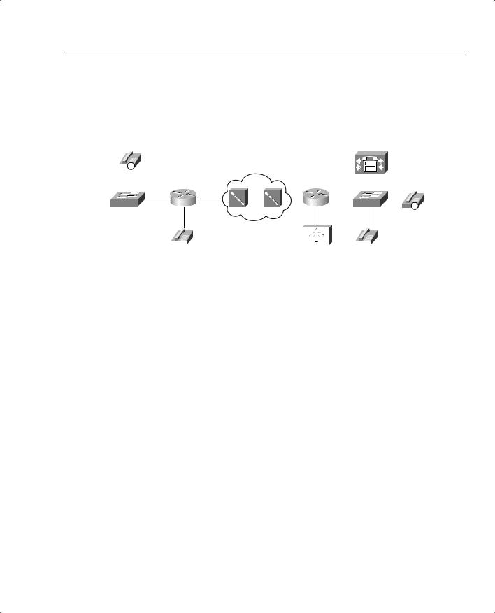
Figure 7-24 shows the framing when FRF.3 and FRF.11 are used, both for IP telephony traffic and for local voice gateway traffic.
![](/html/1438/356/html_8qEWQlgVYy.fRAV/htmlconvd-rT6A6m572x1.jpg)
Foundation Summary 535
Figure 7-24 Framing of Voice Traffic with FRF.3 and FRF.11 VCs
|
|
|
|
With Data VC |
|
|
|
|
|
|
|
|
|
|
|
|
||
|
|
|
|
|
|
|
|
|
IP Telephone Traffic |
|
|
|
|
|
||||
|
|
|
|
|
|
FRF.3 |
IP |
UDP |
RTP |
G.729 |
FRF.3 |
|
|
|
|
|
||
|
|
|
|
|
|
Header |
Voice |
Trailer |
|
|
|
|
|
|||||
|
|
|
|
|
|
|
|
|
Voice Gateway Traffic |
|
|
|
|
|
||||
|
|
|
|
|
|
FRF.3 |
IP |
UDP |
RTP |
G.729 |
FRF.3 |
|
|
|
|
|
||
|
|
IP |
|
|
Header |
Voice |
Trailer |
|
|
|
|
|
||||||
|
|
|
|
|
|
|
|
|
|
|
|
|
|
|
|
|
|
|
|
|
|
|
|
|
|
|
|
|
|
|
|
|
|
|
|
|
|
SW1 |
R1 |
T/1 R2 |
SW2 |
IP |
|
|
|
|
|
|
|
|
|
|
|
|
|
|
|
|
|
|
|
|
|
|
|
|
|
|
|
|
|
|
|
|
|
|
|
|
|
|
|
|
|
|
|
|
|
|
|
|
|
|
|
|
|
|
|
|
|
|
|
|
With VoFR VC |
|
|
|
|
|
|
|
|
IP Telephone Traffic |
|
||||
FRF.3 |
FRF.11 |
IP |
UDP |
RTP |
G.729 |
FRF.3 |
|
|
||||||
|
|
|
||||||||||||
|
Header |
Header |
Voice |
Trailer |
|
|
||||||||
|
|
|
|
|
Voice Gateway Traffic |
|
|
|
|
|||||
|
FRF.3 |
FRF.11 |
G.729 |
FRF.3 |
|
|
|
|
|
|||||
|
Header |
Header |
Voice |
Trailer |
|
|
|
|
|
Table 7-27 summarizes some of the key comparison points about FRF.12 and FRF.11-C.
Table 7-27 FRF.11-C and FRF.12 Comparison
Function |
FRF.12 Behavior |
FRF.11-C Behavior |
|
|
|
Queuing option on the interface |
Dual FIFO |
Dual FIFO |
output queues |
|
|
|
|
|
Classification into the interface |
Based on queuing tool used for |
Voice frames placed in High |
output queues |
shaping, with LLQ and IP RTP |
queue, all others in Normal |
|
Priority putting packets into the |
queue, regardless of shaping |
|
high-priority queue |
queue configuration |
|
|
|
Fragmentation based on size, or |
Based only on size; must be |
Nonvoice frames fragmented, |
type of packet |
careful not to fragment voice |
and voice frames are not, |
|
packets |
regardless of size |
|
|
|
Frame Relay network can be |
No |
Yes |
aware of voice vs. nonvoice |
|
|
frames, and acts accordingly |
|
|
|
|
|
Underlying type of VC, and |
FRF.3, available from most if |
FRF.11, not generally available |
general public availability |
not all public Frame Relay |
from public Frame Relay |
|
services |
services |
|
|
|