


Classification and Marking Tools 207
Example 3-8 PBR Marking Sample 2: VoIP, NetMeeting Audio/Video, HTTP URLs, and Everything Else (Continued)
route-map voip-routemap, permit, sequence 30 Match clauses:
ip address (access-lists): http-acl Set clauses:
ip precedence immediate
Policy routing matches: 834 packets, 1007171 bytes route-map voip-routemap, permit, sequence 40
Match clauses: Set clauses:
ip precedence routine
Policy routing matches: 8132 packets, 11263313 bytes
The output of the show ip policy command lists only sparse information. The show route-map command enables you to view statistical information about what PBR has performed. This command lists statistics for any activities performed by a route map, including when one is used for PBR. Notice that the four sets of classification criteria seen in the configuration are listed in the highlighted portions of the show route-map output, as are packet and byte counters.
PBR Marking Summary
PBR provides another classification and marking tool that examines packet header information to classify and mark packets. PBR is unique compared to the other tools in that it can classify based on information about the route that would be used for forwarding a packet. However, PBR has fewer options for matching header fields for classification as compared with the other tools.
PBR can mark IP precedence, QoS group, as well as the ToS bits. Refer to Table 3-17, in the summary for this chapter, for a complete list of classification and marking fields used by PBR.
PBR provides a strong option for classification and marking in two cases. For applications when marking based on routing information is useful, PBR can look at details about the route used for each packet, and make marking choices. The other application for PBR marking is when policy routing is already needed, and marking needs to be done at the same time. For more general cases of classification and marking, CB marking or CAR is recommended.
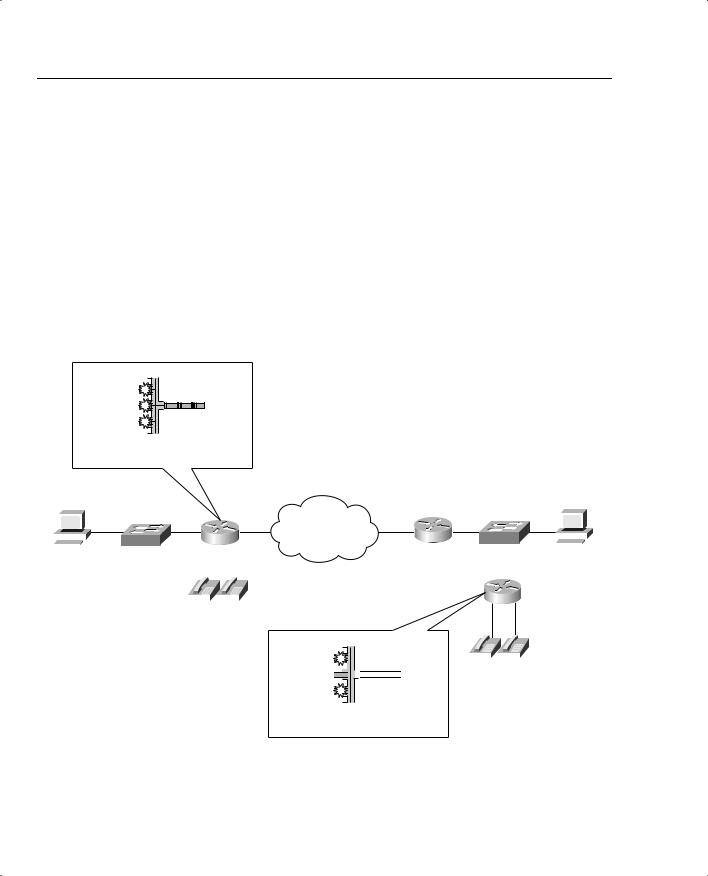
VoIP Dial Peer
IOS voice gateways provide many services to connect the packetized, VoIP network to nonpacketized, traditional voice services, including analog and digital trunks. IOS gateways perform many tasks, but one of the most important tasks is to convert from packetized voice to nonpacketized voice, and vice versa. In other words, voice traffic entering a router on an analog or digital trunk is not carried inside an IP packet, but the IOS gateway converts the incoming


 3001 3002


 Z
Z

Classification and Marking Tools 209
Example 3-9 R1 Voice Gateway Configuration
hostname R1
!
int fastethernet 0/0
ip address 192.168.1.251 255.255.255.0
!
dial-peer voice 3001 voip destination-pattern 3001
session target ipv4:192.168.3.254
!
dial-peer voice 3002 voip destination-pattern 3002
session target ipv4:192.168.3.254
!
dial-peer voice 1001 pots destination-pattern 1001 port 3/0
!
dial-peer voice 1002 pots destination-pattern 1002 port 3/1
Example 3-10 R4 Voice Gateway Configuration
hostname R4
!
int fastethernet 0/0
ip address 192.168.3.254 255.255.255.0
!
dial-peer voice 1001 voip destination-pattern 1001
session target ipv4:192.168.1.251
!
dial-peer voice 1002 voip destination-pattern 1002
session target ipv4:192.168.1.251
!
dial-peer voice 3001 pots destination-pattern 3001 port 3/0
!
dial-peer voice 3002 pots destination-pattern 3002 port 3/1

210 Chapter 3: Classification and Marking
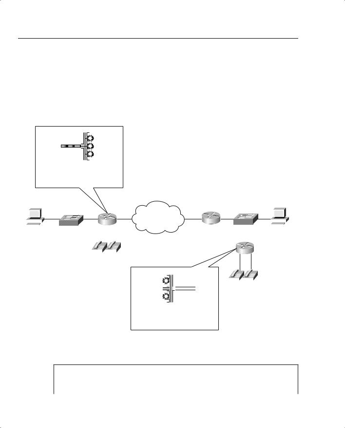
The highlighted portions of the examples focus on the configuration for the physical voice ports on R1, and the VoIP configuration on R4. Both R1 and R4 use dial-peer commands to define their local analog voice trunks and to define peers to which VoIP calls can be made. In Example 3-9, for instance, the highlighted portion of the configuration shows R1’s configuration of the two local analog lines. The two highlighted dial-peer statements use the keyword pots, which stands for plain-old telephone service. The pots keyword implies that the ports associated with this dial peer are traditional analog or digital telephony ports. The physical analog ports are correlated to each dial peer with the port command; in each of these configurations, a two-port FXS card sits inside slot 3 of a 1760-V router. Finally, on R1, the phone number, or dial pattern, associated with each of the analog ports is configured. With just the highlighted configuration in R1, voice calls could be placed between the two extensions (x1001 and x1002).
To place calls to extensions 1001 and 1002 from R4, the dial-peer commands highlighted in Example 3-10 are required. These two dial-peer commands use a voip keyword, which means this dial peer configures information about an entity to which VoIP calls can be placed. The phone number, or dial pattern, is defined with the destination-pattern command again—notice that extensions 1001 and 1002 are again configured. Finally, because these two dial peers configure details about a VoIP call, a local physical port is not referenced. Instead, the sessiontarget ipv4:192.168.1.251 command implies that when these phone numbers are called, to establish a VoIP call, using the IP version 4 IP address shown.
Similarly, R4 defines the local phone numbers and ports for the locally connected phones, and R1 defines VoIP dial peers referring to R4’s phones, so that calls can be initiated from R1.
Dial-peer classification and marking, when you know how to configure the basic dial-peer parameters, is easy. POTS dial peers refer to analog or digital trunks, over which no IP packet is in use—so there is nothing to mark. On VoIP dial peers, the dial peer refers to the IP address of another gateway to which a call is placed. So, by placing the ip precedence 5 dial-peer subcommand under each voip dial-peer, the packets generated for calls matching each dial peer will be marked with IP precedence 5. Example 3-11 lists the R4 configuration, with these changes made; the equivalent changes would be made to R1 as well.
Example 3-11 R4 Voice Gateway Configuration
hostname R4
!
interface fastethernet 0/0
ip address 192.168.3.254 255.255.255.0
!
dial-peer voice 1001 voip destination-pattern 1001
session target ipv4:192.168.1.251 ip precedence 5
no vad
!
dial-peer voice 1002 voip destination-pattern 1002
session target ipv4:192.168.1.251

Classification and Marking Tools 211
Example 3-11 R4 Voice Gateway Configuration (Continued)
ip precedence 5 no vad
!
dial-peer voice 3001 pots destination-pattern 3001 port 3/0
!
dial-peer voice 3002 pots destination-pattern 3002 port 3/1
In the example, the highlighted text shows the ip precedence 5 commands under each voip dial-peer. Packets created for VoIP calls for the configured dial patterns of 1001 and 1002 will be marked with IP precedence 5. The identical commands would be added to R1’s configuration on the VoIP dial peers to achieve the same effect.
Beginning in IOS Releases 12.2(2)XB and 12.2(2)T the ip precedence command has been replaced with the ip qos dscp command. This allows the dial peer to set the IP precedence or the DSCP value for VoIP payload and signaling traffic. Also keep in mind that the current DQOS exam, at the time this book was published, was based on IOS 12.1(5)T—so this command would not be on the current exam. Check the URLs listed in the Introduction for any possible changes.
The command uses the following syntax:
ip qos dscp [number | set-af | set-cs | default | ef][media | signaling]
Table 3-16 outlines the meaning of the parameters of the command.
Table 3-16 IP QoS DSCP Command Options
IP QoS DSCP Options |
Function |
|
|
number |
DSCP value. Valid entries are from 0 to 63. |
|
|
set-af |
Sets DSCP to assured forwarding bit pattern. Acceptable values are as |
|
follows: |
|
AF11, AF12, AF13, AF21, AF22, AF23, AF31, AF32, AF33, AF41, AF42, |
|
AF43 |
|
|
set-cs |
Sets DSCP to class selector code point. Acceptable values are as follows: |
|
CS1, CS2, CS3, CS4, CS5, CS6, CS7 |
|
|
default |
Sets DSCP to default bit pattern 000000. |
|
|
ef |
Sets DSCP to expedited forwarding bit pattern 101110. |
|
|
media |
Applies the specified DSCP value to the media payload packets. |
|
|
signaling |
Applies the specified DSCP value to the signaling packets. |
|
|


 3001 3002


 Z
Z
Classification and Marking Tools 213
Example 3-12 R1 IP QoS DSCP Dial-Peer Configuration (Continued)
!
dial-peer voice 3001 voip destination-pattern 3001 ip qos dscp ef media
ip qos dscp af31 signaling session target ipv4:192.168.3.254
!
dial-peer voice 3002 voip destination-pattern 3002 ip qos dscp ef media
ip qos dscp af31 signaling session target ipv4:192.168.3.254
!
dial-peer voice 1001 pots destination-pattern 1001 port 3/0
!
dial-peer voice 1002 pots destination-pattern 1002 port 3/1
Example 3-13 R4 IP QoS DSCP Dial-Peer Configuration
hostname R4
!
int fastethernet 0/0
ip address 192.168.3.254 255.255.255.0
!
dial-peer voice 1001 voip destination-pattern 1001 ip qos dscp ef media
ip qos dscp af31 signaling session target ipv4:192.168.1.251
!
dial-peer voice 1002 voip destination-pattern 1002 ip qos dscp ef media
ip qos dscp af31 signaling session target ipv4:192.168.1.251
!
dial-peer voice 3001 pots destination-pattern 3001 port 3/0
!
dial-peer voice 3002 pots destination-pattern 3002 port 3/1