

Foundation Summary 405
Foundation Summary
The “Foundation Summary” is a collection of tables and figures that provide a convenient review of many key concepts in this chapter. For those of you already comfortable with the topics in this chapter, this summary could help you recall a few details. For those of you who just read this chapter, this review should help solidify some key facts. For any of you doing your final prep before the exam, these tables and figures are a convenient way to review the day before the exam.
ISPs make the business choice of whether to police, and how aggressively to police. The options reduce to the following three basic options:
•Do not police. To support the traffic, build the network to support the traffic as if all customers will send and receive data at the clock rate of the access link. From a sales perspective, close deals by claiming that no policing will be done, but encourage customers who exceed their contracts to pay for more bandwidth.
•Police at the contracted rate. To support these traffic levels, the network only needs to be built to support the collective contracted rates, although the core would be overbuilt to support new customers. From a sales perspective, encourage customers that are beginning to exceed their contracts to upgrade, and give incentives.
•Police somewhere in between the contracted rate and the access-link clock rate. For instance, ISP1 might police PB Tents at 5 Mbps, when the contract reads 2 Mbps. The network can be built to support the collective policed rates. The sales team can encourage customers to buy a larger contracted rate when they consistently exceed the contracted rate, but keep customer satisfaction higher by pointing out their generosity by only policing at rates much higher than the contracted rates.
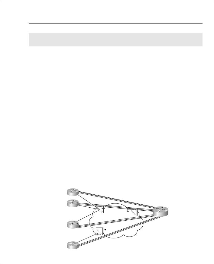
Figure 5-24 points out two cases of egress blocking, using a Frame Relay network as an example.
Figure 5-24 PB Tents Network, Egress Blocking
|
|
|
|
|
|
All VCs 64 kbps CIR |
|
|
|
||||
|
|
|
|
|
|
Cumulative Traffic Can Be |
|
|
|
||||
R1 |
|
|
|
|
24 * 128 kbps = 3.0 Mbps |
|
|
|
|||||
|
|
|
|
|
|
|
|
|
|
|
|
||
|
AR 128 kbps |
|
|
|
|
|
|
|
|
|
|
||
R2 |
|
|
|
|
|
|
|
|
|
|
|
|
|
|
|
|
|
|
|
|
|
|
|
|
|
||
|
AR 128 kbps |
|
|
|
|
|
|
|
|
|
|
|
Main |
|
|
|
|
|
|
|
|
|
|
|
|
||
|
|
|
|
|
|
|
|
|
|
|
|
|
|
AR 128 kbps |
FRS1 |
|
|
FRS2 |
|
|
AR 1.5 Mbps |
||||||
|
|
|
|
|
|
||||||||
|
|
|
|||||||||||
R3 |
|
|
FRS3 |
|
|
|
|||||||
.. |
AR 128 kbps |
|
|
|
|
|
|
|
|
|
|
|
|
|
|
|
|
|
|
|
|
|
|
|
|
||
. |
|
|
|
|
|
|
|
|
|
|
|
|
|
|
|
|
|
|
|
Speed Mismatch Between Main (1.5 Mbps) |
|||||||
R24 |
|
|
|
|
and R24 Access Rate (128 kbps) Causes Blocking |
||||||||

406 Chapter 5: Traffic Policing and Shaping
Table 5-27 summarizes some of the key points about when and where you should consider using policing and shaping.
Table 5-27 Policing and Shaping: When to Use Them, and Where
Topic |
Rationale |
|
|
Why police? |
If a neighboring network can send more traffic than the traffic contract specifies, |
|
policing can be used to enforce the contract, protecting the network from being |
|
overrun with too much traffic. |
|
|
Where to police? |
Typically, policing is performed as packets enter the first device in a network. |
|
Egress policing is also supported, although it is less typical. |
|
|
Why shape? |
The first of two reasons for shaping is when the neighboring network is policing. |
|
Instead of waiting for the neighboring policer to discard traffic, a shaper can |
|
instead delay traffic so that it will not be dropped. |
|
The second reason has to do with the effects of egress blocking. By shaping, |
|
egress blocking can be avoided, or minimized, essentially moving the queues |
|
from inside the service provider cloud, and back into the enterprise routers. By |
|
doing so, the router queuing tools can selectively give better QoS performance to |
|
particular types of traffic. |
|
|
Where to shape? |
Shaping is always an egress function. Typically, shaping is performed on packets |
|
exiting a router, going into another network. This may be the edge between a |
|
router and a multiaccess WAN, or possibly just a link to an ISP. |
|
|
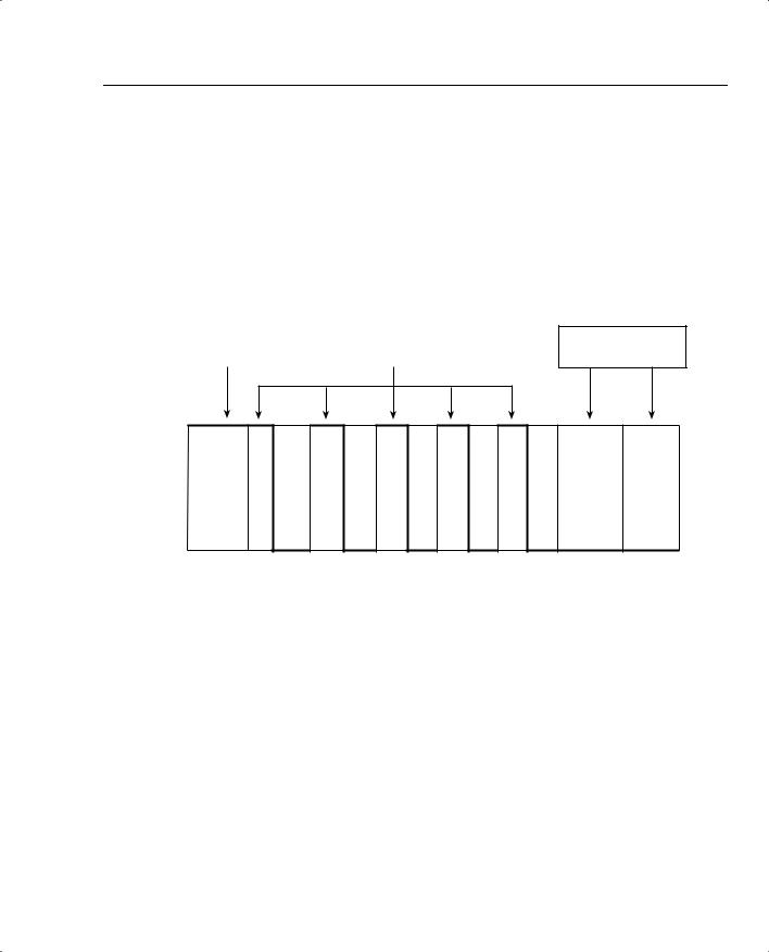
Traffic shaping implements this basic logic by defining a measurement interval, and a number of bits that can be sent in that interval, so that the overall shaped rate is not exceeded. Table 5-28 lists some related definitions.
Table 5-28 Shaping Terminology
Term |
Definition |
|
|
Tc |
Time interval, measured in milliseconds, over which the committed burst (Bc) can be |
|
sent. With many shaping tools, Tc = Bc/CIR. |
|
|
Bc |
Committed burst size, measured in bits. This is the amount of traffic that can be sent |
|
over the interval Tc. Typically also defined in the traffic contract. |
|
|
CIR |
Committed information rate, in bits per second, defines the rate defined in the traffic |
|
contract. |
|
|
Shaped Rate |
The rate, in bits per second, to which a particular configuration wants to shape the |
|
traffic. In some cases, the shaped rate is set to the same value as CIR; in others, |
|
the shaped rate is set to a larger value, with the hope of sending more traffic through |
|
the network. |
|
|
Be |
Excess burst size, in bits. This is the number of bits beyond Bc that can be sent after a |
|
period of inactivity. |
|
|
 PQ Low –

410 Chapter 5: Traffic Policing and Shaping
Table 5-31 Command Reference for Generic Traffic Shaping
|
Command |
Mode and Function |
|
|
|
|
traffic-shape rate bit-rate [burst-size |
Interface configuration mode; enables GTS for a shaped |
|
[excess-burst-size]] |
rate, with optional Bc and Be settings, in bits |
|
|
|
|
traffic-shape group access-list bit-rate |
Interface configuration mode; enables GTS for a shaped |
|
[burst-size [excess-burst-size]] |
rate, only for traffic permitted by the referenced ACL, with |
|
|
optional Bc and Be settings, in bits |
|
|
|
|
traffic-shape adaptive bit-rate |
Interface configuration mode; enables adaptive shaping, |
|
|
and sets the minimum shaped rate |
|
|
|
|
traffic-shape fecn-adapt |
Interface configuration mode; enables the reflection of |
|
|
BECN signals upon receipt of an FECN |
|
|
|
Table 5-32 Exec Command Reference for Generic Traffic Shaping |
||
|
|
|
|
Command |
Function |
|
|
|
|
show traffic-shape [interface-type |
Lists information about the configuration details |
|
interface-number] |
|
|
|
|
|
show traffic-shape queue [interface- |
Lists statistics about the queuing tool used on the shaping |
|
number [dlci dlci-number]] |
queue |
|
|
|
|
show traffic-shape statistics [interface- |
Lists statistics about shaping operation |
|
type interface-number] |
|
|
|
|
Tables 5-33 and 5-34 list the configuration and show commands pertinent to CB shaping.
Table 5-33 Command Reference for Class-Based Shaping
Command |
Mode and Function |
|
|
shape [average | peak] mean-rate [[burst- |
Policy-map class configuration mode; enables shaping |
size] [excess-burst-size]] |
for the class, setting the shaping rate, and optionally |
|
Bc and Be. The average option causes shaping as nor- |
|
mal; the peak option causes Bc + Be to be sent per Tc. |
|
|
Shape adaptive min-rate |
Policy-map class configuration mode; enables the |
|
minimum rate for adaptive shaping. The maximum |
|
rate is configured with the shape average or shape |
|
peak command. |
|
|
Shape fecn-adapt |
Policy-map class configuration mode; enables |
|
reflection of BECN signals upon receipt of an FECN. |
|
|
service-policy {input | output} policy-map- |
Interface or subinterface configuration mode; enables |
name |
CB shaping on the interface. |
|
|


412 Chapter 5: Traffic Policing and Shaping
Table 5-33 Command Reference for Class-Based Shaping (Continued)
|
Command |
Mode and Function |
|
|
|
|
match any |
class-map subcommand; matches all packets. |
|
|
|
|
policy-map policy-map-name |
Global config; names a policy, which is a set of actions |
|
|
to perform. |
|
|
|
|
class name |
policy-map subcommand; identifies which packets on |
|
|
which to perform some action by referring to the |
|
|
classification logic in a class map. |
|
|
|
Table 5-34 Exec Command Reference for Class-Based Shaping |
||
|
|
|
|
Command |
Function |
|
|
|
|
show policy-map policy-map-name |
Lists configuration information about all MQC-based |
|
|
QoS tools |
|
|
|
|
show policy-map interface-spec [input | |
Lists statistical information about the behavior of all |
|
output] [class class-name] |
MQC-based QoS tools |
|
|
|
Tables 5-35 and 5-36 list the configuration and show commands pertinent to FRTS.
Table 5-35 Command Reference for Frame Relay Traffic Shaping
Command |
Mode and Function |
|
|
frame-relay traffic-shaping |
Interface subcommand; enables FRTS on the interface. |
|
|
class name |
Interface DLCI subcommand; enables a specific FRTS |
|
map class for the DLCI. |
|
|
frame-relay class name |
Interface or subinterface command; enables a specific |
|
FRTS map class for the interface or subinterface. |
|
|
map-class frame-relay map-class-name |
Global configuration mode; names a map class, and |
|
places CLI into map-class configuration mode |
|
|
frame-relay priority-group list-number |
Map-class configuration mode; enables PQ for the |
|
shaping queues associated with this map class |
|
|
frame-relay custom-queue-list list-number |
Map-class configuration mode; enables CQ for the |
|
shaping queues associated with this map class |
|
|
frame-relay fair-queue |
Map-class configuration mode; enables WFQ for the |
[congestive_discard_threshold |
shaping queues associated with this map class |
[number_dynamic_conversation_queues |
|
[number_reservable_conversation_queues |
|
[max_buffer_size_for_fair_queues]]]] |
|
|
|

Foundation Summary 413
Table 5-35 Command Reference for Frame Relay Traffic Shaping (Continued)
Command |
Mode and Function |
|
|
service-policy {input | output} policy-map- |
Map-class configuration mode; enables LLQ or |
name |
CBWFQ on the shaping queues associated with the |
|
map class. |
|
|
frame-relay traffic-rate average [peak] |
Map-class configuration mode; sets the shaped rate, |
|
and the EIR*. Bc and Be are calculated from these, |
|
based on Tc of 125ms. |
|
|
frame-relay bc {in | out} bits |
Map-class configuration mode; sets the Bc value. |
|
Alternative configuration option to frame-relay |
|
traffic-rate. |
|
|
frame-relay be {in | out} bits |
Map-class configuration mode; sets the Be value. |
|
Alternative configuration option to frame-relay |
|
traffic-rate. |
|
|
frame-relay cir {in | out} bps |
Map-class configuration mode; sets the CIR value. |
|
Alternative configuration option to frame-relay |
|
traffic-rate. |
|
|
frame-relay adaptive-shaping {becn | |
Map-class configuration mode; enables adaptive |
foresight} |
shaping, specifying either BECN or Foresight for |
|
signaling. |
|
|
frame-relay mincir {in | out} bps |
Map-class configuration mode; sets the minimum CIR |
|
used for adaptive shaping. |
|
|
frame-relay tc milliseconds |
Map-class configuration mode; for 0 CIR VCs, sets the |
|
Tc value. |
|
|
frame-relay qos-autosense |
Interface configuration mode; uses ELMI to automati- |
|
cally discover CIR, Bc, and Be settings for each VC. |
|
|
*EIR = excess information rate
Table 5-36 Exec Command Reference for Frame Relay Traffic Shaping
Command |
Function |
|
|
show frame-relay pvc [interface interface] |
Shows PVC statistics, including shaping statistics |
[dlci] |
|
|
|
show traffic-shape [interface-type interface- |
Shows information about FRTS configuration per VC |
number] |
|
|
|
show traffic-shape queue [interface-number |
Shows information about the queuing tool used with |
[dlci dlci-number]] |
the shaping queue |
|
|
show traffic-shape statistics [interface-type |
Shows traffic-shaping statistics |
interface-number] |
|
|
|


416 Chapter 5: Traffic Policing and Shaping
Table 5-38 Classification Fields Used by CAR and CB Policing (Continued)
Field |
Tool |
Comments |
|
|
|
RTP’s UDP port-number |
CB policing |
RTP uses even numbered UDP ports from |
range |
|
16384–32767 for voice payload. This matching |
|
|
option allows matching a subset of the port |
|
|
numbers, and it matches only the even-numbered |
|
|
ports. |
|
|
|
NBAR protocol types |
CB policing |
Refer to the coverage in Chapter 3 for more |
|
|
details. |
|
|
|
NBAR Citrix applications |
CB policing |
NBAR can recognize different types of Citrix |
|
|
applications; CB marking can use NBAR to |
|
|
classify based on these application types. |
|
|
|
Host Name and URL string |
CB policing |
NBAR can match URL strings using regular |
|
|
expressions, including the host name. CB |
|
|
marking can use NBAR to match these strings |
|
|
for classification. |
|
|
|
Table 5-39 lists the various actions associated with CB policing and CAR.
Table 5-39 Policing Actions Used by CAR and CB Policing
|
|
|
CB |
Action Keyword |
Meaning |
CAR? |
Policer? |
|
|
|
|
drop |
Discards the packet |
Yes |
Yes |
|
|
|
|
transmit |
Forwards the packet |
Yes |
Yes |
|
|
|
|
set-prec-transmit |
Forwards the packet after marking the IP precedence |
Yes |
Yes |
|
value. |
|
|
|
|
|
|
set-qos-transmit |
Forwards the packet after marking the QoS group |
Yes |
Yes |
|
|
|
|
set-dscp-transmit |
Forwards the packet after marking the IP DSCP value |
Yes |
Yes |
|
|
|
|
set-mpls-exp-transmit |
Forwards the packet after marking the MPLS |
Yes |
Yes |
|
Experimental bits |
|
|
|
|
|
|
set-frde-transmit |
Forwards the packet after marking the Frame Relay |
No |
Yes |
|
discard eligibility (DE) bit |
|
|
|
|
|
|
set-clp-transmit |
Forwards the packet after marking the ATM cell loss |
No |
Yes |
|
priority (CLP) bit |
|
|
|
|
|
|
set-prec-continue |
Marks the IP precedence value, and continues to the |
Yes |
No |
|
next nested (cascaded) CAR command |
|
|
|
|
|
|
set-dscp-continue |
Marks the QoS group, and continues to the next |
Yes |
No |
|
nested (cascaded) CAR command |
|
|
|
|
|
|


418 Chapter 5: Traffic Policing and Shaping
Table 5-40 Command Reference for Class-Based Policing (Continued)
|
Command |
Mode and Function |
|
|
|
|
match ip dscp ip-dscp-value [ip-dscp- |
IP DSCP. |
|
value ip-dscp-value ip-dscp-value ip-dscp- |
|
|
value ip-dscp-value ip-dscp-value ip-dscp- |
|
|
value] |
|
|
|
|
|
match ip rtp starting-port-number port- |
RTP’s UDP port-number range. |
|
range |
|
|
|
|
|
match qos-group qos-group-value |
QoS group. |
|
|
|
|
match protocol protocol-name |
NBAR protocol types. |
|
|
|
|
match protocol citrix [app application- |
NBAR Citrix applications. |
|
name-string]. |
|
|
|
|
|
match protocol http [url url-string | host |
Host name and URL string. |
|
hostname-string | mime MIME-type] |
|
|
|
|
|
match any |
All packets. |
|
|
|
|
policy-map policy-map-name |
Global config; names a policy, which is a set of actions |
|
|
to perform. |
|
|
|
|
class name |
policy-map subcommand; identifies which packets on |
|
|
which to perform some action by referring to the |
|
|
classification logic in a class map. |
|
|
|
Table 5-41 Exec Command Reference for Class-Based Policing |
||
|
|
|
|
Command |
Function |
|
|
|
|
show policy-map policy-map-name |
Lists configuration information about all MQC-based |
|
|
QoS tools |
|
|
|
|
show policy-map interface-spec [input | |
Lists statistical information about the behavior of all |
|
output] [class class-name] |
MQC-based QoS tools |
|
|
|
Tables 5-42 and 5-43 list the CAR configuration and show commands, respectively.

|
|
Foundation Summary 419 |
|
|
|
Table 5-42 Configuration Command Reference for CAR |
|
|
|
|
|
|
Command |
Mode and Function |
|
|
|
|
rate-limit {input | output} [access-group |
Interface mode; configures classification, marking, |
|
[rate-limit] acl-index] bps burst-normal |
policing, and enables CAR on the interface |
|
burst-max conform-action conform-action |
|
|
exceed-action exceed-action |
|
|
|
|
|
access-list rate-limit acl-index |
Global mode; creates a CAR ACL, which can match IP |
|
{precedence | mac-address | exp mask |
precedence, MAC addresses, and MPLS Experimental |
|
mask} |
bits |
|
|
|
|
The remaining entries describe the possible actions in the rate-limit command: |
|
|
|
|
|
continue |
Evaluates the next rate-limit command |
|
|
|
|
drop |
Drops the packet |
|
|
|
|
set-dscp-continue |
Sets the differentiated services code point (DSCP) |
|
|
(0 to 63) and evaluates the next rate-limit command. |
|
|
|
|
set-dscp-transmit |
Sends the DSCP and transmits the packet |
|
|
|
|
set-mpls-exp-continue |
Sets the MPLS Experimental bits (0 to 7) and evaluates |
|
|
the next rate-limit command |
|
|
|
|
set-mpls-exp-transmit |
Sets the MPLS Experimental bits (0 to 7) and sends the |
|
|
packet |
|
|
|
|
set-prec-continue |
Sets the IP precedence (0 to 7) and evaluates the next |
|
|
rate-limit command |
|
|
|
|
set-prec-transmit |
Sets the IP precedence (0 to 7) and sends the packet. |
|
|
|
|
set-qos-continue |
Sets the QoS group ID (1 to 99) and evaluates the next |
|
|
rate-limit command |
|
|
|
|
set-qos-transmit |
Sets the QoS group ID (1 to 99) and sends the packet |
|
|
|
|
transmit |
Sends the packet |
|
|
|
Table 5-43 Exec Command Reference for CAR |
|
|
|
|
|
|
Command |
Function |
|
|
|
|
show interfaces [interface-type interface- |
Displays CAR statistics on the interface specified, or on |
|
number] rate-limit |
all interfaces if the interface is not specified |
|
|
|
|
show access-lists rate-limit [acl-index] |
Lists information about the configuration of rate-limit |
|
|
ACLs |
|
|
|

420 Chapter 5: Traffic Policing and Shaping
Table 5-44 summarizes the CAR features, comparing them with CB policing.
Table 5-44 CAR and CB Policing Features Compared
Feature |
CB Policing |
CAR |
|
|
|
Allows conform and exceed action categories |
Yes |
Yes |
|
|
|
Allows violate action category |
Yes |
No |
|
|
|
Polices either all traffic, or a subset through |
Yes |
Yes |
classification |
|
|
|
|
|
Uses MQC for configuration |
Yes |
No |
|
|
|
Allows nested or cascaded policing logic |
No |
Yes |
|
|
|
Can be enabled per subinterface |
Yes |
Yes |
|
|
|
Can be enabled per DLCI on multipoint |
No |
No |
subinterfaces |
|
|
|
|
|
Can set ATM CLP bit |
Yes |
No |
|
|
|
Can set FR DE bit |
Yes |
No |
|
|
|