
- •QoS Overview
- •“Do I Know This Already?” Quiz
- •QoS: Tuning Bandwidth, Delay, Jitter, and Loss Questions
- •Foundation Topics
- •QoS: Tuning Bandwidth, Delay, Jitter, and Loss
- •Bandwidth
- •The clock rate Command Versus the bandwidth Command
- •QoS Tools That Affect Bandwidth
- •Delay
- •Serialization Delay
- •Propagation Delay
- •Queuing Delay
- •Forwarding Delay
- •Shaping Delay
- •Network Delay
- •Delay Summary
- •QoS Tools That Affect Delay
- •Jitter
- •QoS Tools That Affect Jitter
- •Loss
- •QoS Tools That Affect Loss
- •Summary: QoS Characteristics: Bandwidth, Delay, Jitter, and Loss
- •Voice Basics
- •Voice Bandwidth Considerations
- •Voice Delay Considerations
- •Voice Jitter Considerations
- •Voice Loss Considerations
- •Video Basics
- •Video Bandwidth Considerations
- •Video Delay Considerations
- •Video Jitter Considerations
- •Video Loss Considerations
- •Comparing Voice and Video: Summary
- •IP Data Basics
- •Data Bandwidth Considerations
- •Data Delay Considerations
- •Data Jitter Considerations
- •Data Loss Considerations
- •Comparing Voice, Video, and Data: Summary
- •Foundation Summary
- •QoS Tools and Architectures
- •“Do I Know This Already?” Quiz
- •QoS Tools Questions
- •Differentiated Services Questions
- •Integrated Services Questions
- •Foundation Topics
- •Introduction to IOS QoS Tools
- •Queuing
- •Queuing Tools
- •Shaping and Policing
- •Shaping and Policing Tools
- •Congestion Avoidance
- •Congestion-Avoidance Tools
- •Call Admission Control and RSVP
- •CAC Tools
- •Management Tools
- •Summary
- •The Good-Old Common Sense QoS Model
- •GOCS Flow-Based QoS
- •GOCS Class-Based QoS
- •The Differentiated Services QoS Model
- •DiffServ Per-Hop Behaviors
- •The Class Selector PHB and DSCP Values
- •The Assured Forwarding PHB and DSCP Values
- •The Expedited Forwarding PHB and DSCP Values
- •The Integrated Services QoS Model
- •Foundation Summary
- •“Do I Know This Already?” Quiz Questions
- •CAR, PBR, and CB Marking Questions
- •Foundation Topics
- •Marking
- •IP Header QoS Fields: Precedence and DSCP
- •LAN Class of Service (CoS)
- •Other Marking Fields
- •Summary of Marking Fields
- •Class-Based Marking (CB Marking)
- •Network-Based Application Recognition (NBAR)
- •CB Marking show Commands
- •CB Marking Summary
- •Committed Access Rate (CAR)
- •CAR Marking Summary
- •Policy-Based Routing (PBR)
- •PBR Marking Summary
- •VoIP Dial Peer
- •VoIP Dial-Peer Summary
- •Foundation Summary
- •Congestion Management
- •“Do I Know This Already?” Quiz
- •Queuing Concepts Questions
- •WFQ and IP RTP Priority Questions
- •CBWFQ and LLQ Questions
- •Comparing Queuing Options Questions
- •Foundation Topics
- •Queuing Concepts
- •Output Queues, TX Rings, and TX Queues
- •Queuing on Interfaces Versus Subinterfaces and Virtual Circuits (VCs)
- •Summary of Queuing Concepts
- •Queuing Tools
- •FIFO Queuing
- •Priority Queuing
- •Custom Queuing
- •Weighted Fair Queuing (WFQ)
- •WFQ Scheduler: The Net Effect
- •WFQ Scheduling: The Process
- •WFQ Drop Policy, Number of Queues, and Queue Lengths
- •WFQ Summary
- •Class-Based WFQ (CBWFQ)
- •CBWFQ Summary
- •Low Latency Queuing (LLQ)
- •LLQ with More Than One Priority Queue
- •IP RTP Priority
- •Summary of Queuing Tool Features
- •Foundation Summary
- •Conceptual Questions
- •Priority Queuing and Custom Queuing
- •CBWFQ, LLQ, IP RTP Priority
- •Comparing Queuing Tool Options
- •“Do I Know This Already?” Quiz
- •Shaping and Policing Concepts Questions
- •Policing with CAR and CB Policer Questions
- •Shaping with FRTS, GTS, DTS, and CB Shaping
- •Foundation Topics
- •When and Where to Use Shaping and Policing
- •How Shaping Works
- •Where to Shape: Interfaces, Subinterfaces, and VCs
- •How Policing Works
- •CAR Internals
- •CB Policing Internals
- •Policing, but Not Discarding
- •Foundation Summary
- •Shaping and Policing Concepts
- •“Do I Know This Already?” Quiz
- •Congestion-Avoidance Concepts and RED Questions
- •WRED Questions
- •FRED Questions
- •Foundation Topics
- •TCP and UDP Reactions to Packet Loss
- •Tail Drop, Global Synchronization, and TCP Starvation
- •Random Early Detection (RED)
- •Weighted RED (WRED)
- •How WRED Weights Packets
- •WRED and Queuing
- •WRED Summary
- •Flow-Based WRED (FRED)
- •Foundation Summary
- •Congestion-Avoidance Concepts and Random Early Detection (RED)
- •Weighted RED (WRED)
- •Flow-Based WRED (FRED)
- •“Do I Know This Already?” Quiz
- •Compression Questions
- •Link Fragmentation and Interleave Questions
- •Foundation Topics
- •Payload and Header Compression
- •Payload Compression
- •Header Compression
- •Link Fragmentation and Interleaving
- •Multilink PPP LFI
- •Maximum Serialization Delay and Optimum Fragment Sizes
- •Frame Relay LFI Using FRF.12
- •Choosing Fragment Sizes for Frame Relay
- •Fragmentation with More Than One VC on a Single Access Link
- •FRF.11-C and FRF.12 Comparison
- •Foundation Summary
- •Compression Tools
- •LFI Tools
- •“Do I Know This Already?” Quiz
- •Foundation Topics
- •Call Admission Control Overview
- •Call Rerouting Alternatives
- •Bandwidth Engineering
- •CAC Mechanisms
- •CAC Mechanism Evaluation Criteria
- •Local Voice CAC
- •Physical DS0 Limitation
- •Max-Connections
- •Voice over Frame Relay—Voice Bandwidth
- •Trunk Conditioning
- •Local Voice Busyout
- •Measurement-Based Voice CAC
- •Service Assurance Agents
- •SAA Probes Versus Pings
- •SAA Service
- •Calculated Planning Impairment Factor
- •Advanced Voice Busyout
- •PSTN Fallback
- •SAA Probes Used for PSTN Fallback
- •IP Destination Caching
- •SAA Probe Format
- •PSTN Fallback Scalability
- •PSTN Fallback Summary
- •Resource-Based CAC
- •Resource Availability Indication
- •Gateway Calculation of Resources
- •RAI in Service Provider Networks
- •RAI in Enterprise Networks
- •RAI Operation
- •RAI Platform Support
- •Cisco CallManager Resource-Based CAC
- •Location-Based CAC Operation
- •Locations and Regions
- •Calculation of Resources
- •Automatic Alternate Routing
- •Location-Based CAC Summary
- •Gatekeeper Zone Bandwidth
- •Gatekeeper Zone Bandwidth Operation
- •Single-Zone Topology
- •Multizone Topology
- •Zone-per-Gateway Design
- •Gatekeeper in CallManager Networks
- •Zone Bandwidth Calculation
- •Gatekeeper Zone Bandwidth Summary
- •Integrated Services / Resource Reservation Protocol
- •RSVP Levels of Service
- •RSVP Operation
- •RSVP/H.323 Synchronization
- •Bandwidth per Codec
- •Subnet Bandwidth Management
- •Monitoring and Troubleshooting RSVP
- •RSVP CAC Summary
- •Foundation Summary
- •Call Admission Control Concepts
- •Local-Based CAC
- •Measurement-Based CAC
- •Resources-Based CAC
- •“Do I Know This Already?” Quiz
- •QoS Management Tools Questions
- •QoS Design Questions
- •Foundation Topics
- •QoS Management Tools
- •QoS Device Manager
- •QoS Policy Manager
- •Service Assurance Agent
- •Internetwork Performance Monitor
- •Service Management Solution
- •QoS Management Tool Summary
- •QoS Design for the Cisco QoS Exams
- •Four-Step QoS Design Process
- •Step 1: Determine Customer Priorities/QoS Policy
- •Step 2: Characterize the Network
- •Step 3: Implement the Policy
- •Step 4: Monitor the Network
- •QoS Design Guidelines for Voice and Video
- •Voice and Video: Bandwidth, Delay, Jitter, and Loss Requirements
- •Voice and Video QoS Design Recommendations
- •Foundation Summary
- •QoS Management
- •QoS Design
- •“Do I Know This Already?” Quiz
- •Foundation Topics
- •The Need for QoS on the LAN
- •Layer 2 Queues
- •Drop Thresholds
- •Trust Boundries
- •Cisco Catalyst Switch QoS Features
- •Catalyst 6500 QoS Features
- •Supervisor and Switching Engine
- •Policy Feature Card
- •Ethernet Interfaces
- •QoS Flow on the Catalyst 6500
- •Ingress Queue Scheduling
- •Layer 2 Switching Engine QoS Frame Flow
- •Layer 3 Switching Engine QoS Packet Flow
- •Egress Queue Scheduling
- •Catalyst 6500 QoS Summary
- •Cisco Catalyst 4500/4000 QoS Features
- •Supervisor Engine I and II
- •Supervisor Engine III and IV
- •Cisco Catalyst 3550 QoS Features
- •Cisco Catalyst 3524 QoS Features
- •CoS-to-Egress Queue Mapping for the Catalyst OS Switch
- •Layer-2-to-Layer 3 Mapping
- •Connecting a Catalyst OS Switch to WAN Segments
- •Displaying QoS Settings for the Catalyst OS Switch
- •Enabling QoS for the Catalyst IOS Switch
- •Enabling Priority Queuing for the Catalyst IOS Switch
- •CoS-to-Egress Queue Mapping for the Catalyst IOS Switch
- •Layer 2-to-Layer 3 Mapping
- •Connecting a Catalyst IOS Switch to Distribution Switches or WAN Segments
- •Displaying QoS Settings for the Catalyst IOS Switch
- •Foundation Summary
- •LAN QoS Concepts
- •Catalyst 6500 Series of Switches
- •Catalyst 4500/4000 Series of Switches
- •Catalyst 3550/3524 Series of Switches
- •QoS: Tuning Bandwidth, Delay, Jitter, and Loss
- •QoS Tools
- •Differentiated Services
- •Integrated Services
- •CAR, PBR, and CB Marking
- •Queuing Concepts
- •WFQ and IP RTP Priority
- •CBWFQ and LLQ
- •Comparing Queuing Options
- •Conceptual Questions
- •Priority Queuing and Custom Queuing
- •CBWFQ, LLQ, IP RTP Priority
- •Comparing Queuing Tool Options
- •Shaping and Policing Concepts
- •Policing with CAR and CB Policer
- •Shaping with FRTS, GTS, DTS, and CB Shaping
- •Shaping and Policing Concepts
- •Congestion-Avoidance Concepts and RED
- •WRED
- •FRED
- •Congestion-Avoidance Concepts and Random Early Detection (RED)
- •Weighted RED (WRED)
- •Flow-Based WRED (FRED)
- •Compression
- •Link Fragmentation and Interleave
- •Compression Tools
- •LFI Tools
- •Call Admission Control Concepts
- •Local-Based CAC
- •Measurement-Based CAC
- •Resources-Based CAC
- •QoS Management Tools
- •QoS Design
- •QoS Management
- •QoS Design
- •LAN QoS Concepts
- •Catalyst 6500 Series of Switches
- •Catalyst 4500/4000 Series of Switches
- •Catalyst 3550/3524 Series of Switches
- •Foundation Topics
- •QPPB Route Marking: Step 1
- •QPPB Per-Packet Marking: Step 2
- •QPPB: The Hidden Details
- •QPPB Summary
- •Flow-Based dWFQ
- •ToS-Based dWFQ
- •Distributed QoS Group–Based WFQ
- •Summary: dWFQ Options

Resource-Based CAC 591
Table 8-13 RAI CAC Evaluation Criteria (Continued)
Evaluation Criteria |
Value |
|
|
Per call, interface, or endpoint |
Per gateway |
|
|
Topology awareness |
None |
|
|
Guarantees QoS for duration of call |
None |
|
|
Postdial delay |
None |
|
|
Messaging network overhead |
Occasional RAI toggle between gateway and gatekeeper |
|
|
Cisco CallManager Resource-Based CAC
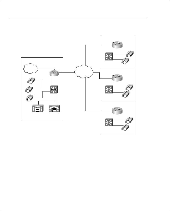
The term “locations” refers to a CAC feature in a Cisco CallManager centralized callprocessing environment. Because a centralized call-processing model is deployed in a hub- and-spoke fashion without the use of a terminating gateway at each spoke, an IP telephony CAC mechanism must be used to protect the desired number of voice conversations. Locations are designed to work in this nondistributed environment.
Figure 8-20 shows a typical CallManager centralized call-processing model.
Location-Based CAC Operation
The Cisco CallManager centralized call-processing model uses a hub-and-spoke topology. The host site, or hub, is the location of the primary Cisco CallManager controlling the network while the remote sites, containing IP endpoints registered to the primary CallManager, represent the spokes. The Cisco CallManager Administration web page can be used to create locations and assign IP endpoints, such as IP Phones, to these locations. After the locations have been created and devices have been assigned, you can allocate bandwidth for conversations between the hub and each spoke locations.
For calls between IP endpoints in the host site of Figure 8-20, the available bandwidth is assumed to be unlimited, and CAC is not considered. However, calls between the host site and remote sites travel over WAN links that have limited available bandwidth. As additional calls are placed between IP endpoints over the WAN links, the audio quality of each voice conversation can begin to degrade. To avoid this degradation in audio quality in a CallManager centralized call-processing deployment, you can use the locations feature to define the amount of available bandwidth allocated to CallManager controlled devices at each location and thereby decrease the number of allowed calls on the link.

592 |
Chapter 8: Call Admission Control and QoS Signaling |
|
|
|
||||
Figure 8-20 CallManager Centralized Call-Processing Model |
|
|
|
|||||
|
|
|
|
|
|
256 kbps |
Remote Site 1 |
|
|
|
|
|
|
|
|
|
|
|
|
|
|
|
|
Circuit |
|
|
|
|
|
|
|
|
|
|
IP |
|
|
Host Site |
|
|
|
Catalyst |
IP |
|
|
|
|
|
|
|
|
||
|
|
|
|
|
|
|
Switch |
|
|
|
|
|
|
|
|
|
|
|
PSTN |
T1 PRI |
786 kbps |
|
|
|
|
|
|
|
|
|
|
|
|
||
|
|
|
|
Circuit |
IP WAN |
|
Remote Site 2 |
|
|
IP |
|
|
|
|
256 kbps |
|
|
|
|
|
|
|
Circuit |
|
|
|
|
IP |
|
|
|
|
|
|
IP |
|
|
|
|
|
|
|
|
|
|
|
|
Catalyst |
|
|
|
Catalyst |
IP |
|
|
|
Switch |
|
|
|
Switch |
|
|
IP |
|
|
|
|
|
||
|
|
|
|
|
|
|
|
|
|
|
|
|
|
|
|
Remote Site 3 |
|
|
CallManager |
CallManager |
|
|
256 kbps |
|
|
|
|
|
|
Circuit |
|
|
|||
|
Publisher |
Subscriber |
|
|
|
|
||
|
|
|
|
|
|
|||
|
|
|
|
|
|
|
|
IP |
|
|
|
|
|
|
|
Catalyst |
IP |
|
|
|
|
|
|
|
Switch |
|
|
|
|
|
|
|
|
|
The amount of bandwidth allocated by CallManager locations is used to track the number of voice conversations in progress across an IP WAN link on a per-CallManager basis. CallManager servers in a cluster are not aware of calls that have been set up by other members in the cluster. To effectively use location-based CAC, all devices in the same location must register with the same centralized CallManager server.
Locations and Regions
In Cisco CallManager, locations work in conjunction with regions to define how voice conversations are carried over a WAN link. Regions define the type of compression, such as G.711 or G.729, used on the link, and locations define the amount of available bandwidth allocated for that link.

Resource-Based CAC 593
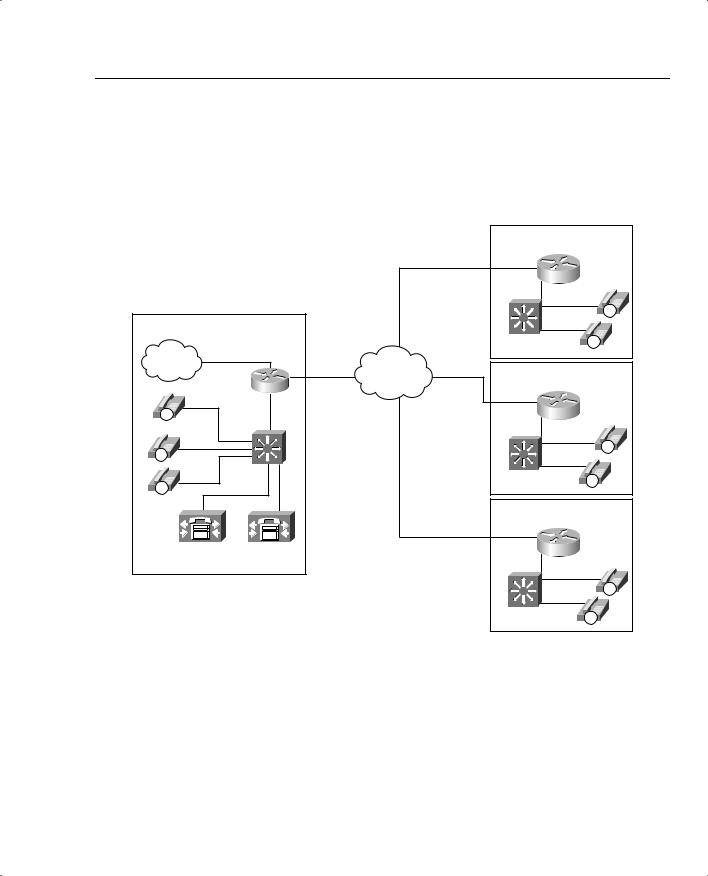
Figure 8-21 illustrates a CallManager centralized call-processing model with three remote sites. Each remote site has a location name that all IP endpoints in that location are associated with and a region that determines which codec is be used for voice conversations to IP endpoints in this location.
Figure 8-21 CallManager Centralized Call-Processing Model with Regions and Locations Defined
|
|
|
|
|
Location: Atlanta |
|
|
|
|
|
256 kbps |
Region: A |
|
|
|
|
|
|
|
|
|
|
|
|
Circuit |
|
|
|
|
|
|
|
|
IP |
|
Host Site |
|
|
|
|
|
|
|
|
|
|
Catalyst |
IP |
|
T1 PRI |
768 kbps |
|
Switch |
|
|
PSTN |
|
|
|
|||
|
|
|
Location: San Jose |
|||
|
|
|
Circuit |
IP WAN |
||
|
|
|
|
Region: B |
|
|
|
|
|
|
256 kbps |
|
|
|
|
|
|
Circuit |
|
|
IP |
|
|
|
|
|
|
IP |
|
|
|
|
|
IP |
|
|
|
|
|
|
|
|
|
Catalyst |
|
|
Catalyst |
IP |
|
|
Switch |
|
|
||
IP |
|
|
|
Switch |
||
|
|
|
|
|
||
|
|
|
|
|
Location: Dallas |
|
|
|
|
|
|
Region: C |
|
CallManager |
CallManager |
|
256 kbps |
|
|
|
|
Circuit |
|
|
|||
Publisher |
Subscriber |
|
|
|
||
|
|
|
|
|||
|
|
|
|
|
|
IP |
|
|
|
|
|
Catalyst |
IP |
|
|
|
|
|
Switch |
|
|
|
|
|
|
|
Each IP endpoint uses the G.711 codec for voice conversations with other endpoints in the same region. When an IP endpoint establishes a voice conversation with an IP endpoint in another region, the G.729 codec is used. The following examples illustrate this:
•HQ IP Phone A calls HQ IP Phone B—Because both IP Phones reside in the same region, the G.711 codec is used.
•HQ IP Phone A calls Atlanta IP Phone A—Because these IP Phones reside in different regions, the G.729 codec is used.

594 Chapter 8: Call Admission Control and QoS Signaling
Calculation of Resources
After the regions have been defined and all devices have been configured to reside in the desired location, you can begin to allocate the desired bandwidth between the locations to use for CAC. This allocated bandwidth does not reflect the actual bandwidth required to establish voice conversations; instead, the allocated bandwidth is a means for CallManager to provide CAC. CAC is achieved by defining a maximum amount of bandwidth per location to use and then subtract a given amount, dependent upon the codec used, from that maximum for each established voice conversation. In this way, CallManager has the capability to deny or reroute call attempts that exceed the configured bandwidth capacity.
Table 8-14 shows the amount of bandwidth that is subtracted, per call, from the total allotted bandwidth for a configured region.
Table 8-14 Location-Based CAC Resource Calculations
Codec |
Bandwidth Reserved |
|
|
G.711 |
80 kbps |
|
|
G.729 |
24 kbps |
|
|
G.723 |
24 kbps |
|
|
GSM |
29 kbps |
|
|
Wideband |
272 kbps |
|
|
In Figure 8-21, suppose that you need to protect six simultaneous calls between the HQ and Atlanta locations, but allow only four between the HQ and Dallas location and three between the HQ and San Jose location. Because each region has been configured to use the G.729 codec between regions, each of these voice conversations represent 24 kbps to the configured location. Remember that the location bandwidth does not represent the actual bandwidth in use.
For the Atlanta location to allow 6 simultaneous calls, the Atlanta Location Bandwidth needs to be configured for 144 kbps, as shown in the following calculation:
6 calls = 6 * 24 kbps = 144 kbps
For the Dallas location to allow 4 simultaneous calls, the Dallas location bandwidth needs to be configured for 48 kbps, as shown in the following calculation:
4 calls = 4 * 24 kbps = 48 kbps
Finally, for the San Jose location to allow 3 simultaneous calls, the San Jose location bandwidth needs to be configured for 72 kbps, as shown in the following calculation:
3 Calls = 3 * 24 kbps = 72 kbps
The link to the Atlanta location, configured for 144 kbps, could support 1 G.711 call at 80 kbps, 6 simultaneous G.729 calls at 24 kbps each, or 1 G.711 call and 2 G.729 calls simultaneously.