
- •QoS Overview
- •“Do I Know This Already?” Quiz
- •QoS: Tuning Bandwidth, Delay, Jitter, and Loss Questions
- •Foundation Topics
- •QoS: Tuning Bandwidth, Delay, Jitter, and Loss
- •Bandwidth
- •The clock rate Command Versus the bandwidth Command
- •QoS Tools That Affect Bandwidth
- •Delay
- •Serialization Delay
- •Propagation Delay
- •Queuing Delay
- •Forwarding Delay
- •Shaping Delay
- •Network Delay
- •Delay Summary
- •QoS Tools That Affect Delay
- •Jitter
- •QoS Tools That Affect Jitter
- •Loss
- •QoS Tools That Affect Loss
- •Summary: QoS Characteristics: Bandwidth, Delay, Jitter, and Loss
- •Voice Basics
- •Voice Bandwidth Considerations
- •Voice Delay Considerations
- •Voice Jitter Considerations
- •Voice Loss Considerations
- •Video Basics
- •Video Bandwidth Considerations
- •Video Delay Considerations
- •Video Jitter Considerations
- •Video Loss Considerations
- •Comparing Voice and Video: Summary
- •IP Data Basics
- •Data Bandwidth Considerations
- •Data Delay Considerations
- •Data Jitter Considerations
- •Data Loss Considerations
- •Comparing Voice, Video, and Data: Summary
- •Foundation Summary
- •QoS Tools and Architectures
- •“Do I Know This Already?” Quiz
- •QoS Tools Questions
- •Differentiated Services Questions
- •Integrated Services Questions
- •Foundation Topics
- •Introduction to IOS QoS Tools
- •Queuing
- •Queuing Tools
- •Shaping and Policing
- •Shaping and Policing Tools
- •Congestion Avoidance
- •Congestion-Avoidance Tools
- •Call Admission Control and RSVP
- •CAC Tools
- •Management Tools
- •Summary
- •The Good-Old Common Sense QoS Model
- •GOCS Flow-Based QoS
- •GOCS Class-Based QoS
- •The Differentiated Services QoS Model
- •DiffServ Per-Hop Behaviors
- •The Class Selector PHB and DSCP Values
- •The Assured Forwarding PHB and DSCP Values
- •The Expedited Forwarding PHB and DSCP Values
- •The Integrated Services QoS Model
- •Foundation Summary
- •“Do I Know This Already?” Quiz Questions
- •CAR, PBR, and CB Marking Questions
- •Foundation Topics
- •Marking
- •IP Header QoS Fields: Precedence and DSCP
- •LAN Class of Service (CoS)
- •Other Marking Fields
- •Summary of Marking Fields
- •Class-Based Marking (CB Marking)
- •Network-Based Application Recognition (NBAR)
- •CB Marking show Commands
- •CB Marking Summary
- •Committed Access Rate (CAR)
- •CAR Marking Summary
- •Policy-Based Routing (PBR)
- •PBR Marking Summary
- •VoIP Dial Peer
- •VoIP Dial-Peer Summary
- •Foundation Summary
- •Congestion Management
- •“Do I Know This Already?” Quiz
- •Queuing Concepts Questions
- •WFQ and IP RTP Priority Questions
- •CBWFQ and LLQ Questions
- •Comparing Queuing Options Questions
- •Foundation Topics
- •Queuing Concepts
- •Output Queues, TX Rings, and TX Queues
- •Queuing on Interfaces Versus Subinterfaces and Virtual Circuits (VCs)
- •Summary of Queuing Concepts
- •Queuing Tools
- •FIFO Queuing
- •Priority Queuing
- •Custom Queuing
- •Weighted Fair Queuing (WFQ)
- •WFQ Scheduler: The Net Effect
- •WFQ Scheduling: The Process
- •WFQ Drop Policy, Number of Queues, and Queue Lengths
- •WFQ Summary
- •Class-Based WFQ (CBWFQ)
- •CBWFQ Summary
- •Low Latency Queuing (LLQ)
- •LLQ with More Than One Priority Queue
- •IP RTP Priority
- •Summary of Queuing Tool Features
- •Foundation Summary
- •Conceptual Questions
- •Priority Queuing and Custom Queuing
- •CBWFQ, LLQ, IP RTP Priority
- •Comparing Queuing Tool Options
- •“Do I Know This Already?” Quiz
- •Shaping and Policing Concepts Questions
- •Policing with CAR and CB Policer Questions
- •Shaping with FRTS, GTS, DTS, and CB Shaping
- •Foundation Topics
- •When and Where to Use Shaping and Policing
- •How Shaping Works
- •Where to Shape: Interfaces, Subinterfaces, and VCs
- •How Policing Works
- •CAR Internals
- •CB Policing Internals
- •Policing, but Not Discarding
- •Foundation Summary
- •Shaping and Policing Concepts
- •“Do I Know This Already?” Quiz
- •Congestion-Avoidance Concepts and RED Questions
- •WRED Questions
- •FRED Questions
- •Foundation Topics
- •TCP and UDP Reactions to Packet Loss
- •Tail Drop, Global Synchronization, and TCP Starvation
- •Random Early Detection (RED)
- •Weighted RED (WRED)
- •How WRED Weights Packets
- •WRED and Queuing
- •WRED Summary
- •Flow-Based WRED (FRED)
- •Foundation Summary
- •Congestion-Avoidance Concepts and Random Early Detection (RED)
- •Weighted RED (WRED)
- •Flow-Based WRED (FRED)
- •“Do I Know This Already?” Quiz
- •Compression Questions
- •Link Fragmentation and Interleave Questions
- •Foundation Topics
- •Payload and Header Compression
- •Payload Compression
- •Header Compression
- •Link Fragmentation and Interleaving
- •Multilink PPP LFI
- •Maximum Serialization Delay and Optimum Fragment Sizes
- •Frame Relay LFI Using FRF.12
- •Choosing Fragment Sizes for Frame Relay
- •Fragmentation with More Than One VC on a Single Access Link
- •FRF.11-C and FRF.12 Comparison
- •Foundation Summary
- •Compression Tools
- •LFI Tools
- •“Do I Know This Already?” Quiz
- •Foundation Topics
- •Call Admission Control Overview
- •Call Rerouting Alternatives
- •Bandwidth Engineering
- •CAC Mechanisms
- •CAC Mechanism Evaluation Criteria
- •Local Voice CAC
- •Physical DS0 Limitation
- •Max-Connections
- •Voice over Frame Relay—Voice Bandwidth
- •Trunk Conditioning
- •Local Voice Busyout
- •Measurement-Based Voice CAC
- •Service Assurance Agents
- •SAA Probes Versus Pings
- •SAA Service
- •Calculated Planning Impairment Factor
- •Advanced Voice Busyout
- •PSTN Fallback
- •SAA Probes Used for PSTN Fallback
- •IP Destination Caching
- •SAA Probe Format
- •PSTN Fallback Scalability
- •PSTN Fallback Summary
- •Resource-Based CAC
- •Resource Availability Indication
- •Gateway Calculation of Resources
- •RAI in Service Provider Networks
- •RAI in Enterprise Networks
- •RAI Operation
- •RAI Platform Support
- •Cisco CallManager Resource-Based CAC
- •Location-Based CAC Operation
- •Locations and Regions
- •Calculation of Resources
- •Automatic Alternate Routing
- •Location-Based CAC Summary
- •Gatekeeper Zone Bandwidth
- •Gatekeeper Zone Bandwidth Operation
- •Single-Zone Topology
- •Multizone Topology
- •Zone-per-Gateway Design
- •Gatekeeper in CallManager Networks
- •Zone Bandwidth Calculation
- •Gatekeeper Zone Bandwidth Summary
- •Integrated Services / Resource Reservation Protocol
- •RSVP Levels of Service
- •RSVP Operation
- •RSVP/H.323 Synchronization
- •Bandwidth per Codec
- •Subnet Bandwidth Management
- •Monitoring and Troubleshooting RSVP
- •RSVP CAC Summary
- •Foundation Summary
- •Call Admission Control Concepts
- •Local-Based CAC
- •Measurement-Based CAC
- •Resources-Based CAC
- •“Do I Know This Already?” Quiz
- •QoS Management Tools Questions
- •QoS Design Questions
- •Foundation Topics
- •QoS Management Tools
- •QoS Device Manager
- •QoS Policy Manager
- •Service Assurance Agent
- •Internetwork Performance Monitor
- •Service Management Solution
- •QoS Management Tool Summary
- •QoS Design for the Cisco QoS Exams
- •Four-Step QoS Design Process
- •Step 1: Determine Customer Priorities/QoS Policy
- •Step 2: Characterize the Network
- •Step 3: Implement the Policy
- •Step 4: Monitor the Network
- •QoS Design Guidelines for Voice and Video
- •Voice and Video: Bandwidth, Delay, Jitter, and Loss Requirements
- •Voice and Video QoS Design Recommendations
- •Foundation Summary
- •QoS Management
- •QoS Design
- •“Do I Know This Already?” Quiz
- •Foundation Topics
- •The Need for QoS on the LAN
- •Layer 2 Queues
- •Drop Thresholds
- •Trust Boundries
- •Cisco Catalyst Switch QoS Features
- •Catalyst 6500 QoS Features
- •Supervisor and Switching Engine
- •Policy Feature Card
- •Ethernet Interfaces
- •QoS Flow on the Catalyst 6500
- •Ingress Queue Scheduling
- •Layer 2 Switching Engine QoS Frame Flow
- •Layer 3 Switching Engine QoS Packet Flow
- •Egress Queue Scheduling
- •Catalyst 6500 QoS Summary
- •Cisco Catalyst 4500/4000 QoS Features
- •Supervisor Engine I and II
- •Supervisor Engine III and IV
- •Cisco Catalyst 3550 QoS Features
- •Cisco Catalyst 3524 QoS Features
- •CoS-to-Egress Queue Mapping for the Catalyst OS Switch
- •Layer-2-to-Layer 3 Mapping
- •Connecting a Catalyst OS Switch to WAN Segments
- •Displaying QoS Settings for the Catalyst OS Switch
- •Enabling QoS for the Catalyst IOS Switch
- •Enabling Priority Queuing for the Catalyst IOS Switch
- •CoS-to-Egress Queue Mapping for the Catalyst IOS Switch
- •Layer 2-to-Layer 3 Mapping
- •Connecting a Catalyst IOS Switch to Distribution Switches or WAN Segments
- •Displaying QoS Settings for the Catalyst IOS Switch
- •Foundation Summary
- •LAN QoS Concepts
- •Catalyst 6500 Series of Switches
- •Catalyst 4500/4000 Series of Switches
- •Catalyst 3550/3524 Series of Switches
- •QoS: Tuning Bandwidth, Delay, Jitter, and Loss
- •QoS Tools
- •Differentiated Services
- •Integrated Services
- •CAR, PBR, and CB Marking
- •Queuing Concepts
- •WFQ and IP RTP Priority
- •CBWFQ and LLQ
- •Comparing Queuing Options
- •Conceptual Questions
- •Priority Queuing and Custom Queuing
- •CBWFQ, LLQ, IP RTP Priority
- •Comparing Queuing Tool Options
- •Shaping and Policing Concepts
- •Policing with CAR and CB Policer
- •Shaping with FRTS, GTS, DTS, and CB Shaping
- •Shaping and Policing Concepts
- •Congestion-Avoidance Concepts and RED
- •WRED
- •FRED
- •Congestion-Avoidance Concepts and Random Early Detection (RED)
- •Weighted RED (WRED)
- •Flow-Based WRED (FRED)
- •Compression
- •Link Fragmentation and Interleave
- •Compression Tools
- •LFI Tools
- •Call Admission Control Concepts
- •Local-Based CAC
- •Measurement-Based CAC
- •Resources-Based CAC
- •QoS Management Tools
- •QoS Design
- •QoS Management
- •QoS Design
- •LAN QoS Concepts
- •Catalyst 6500 Series of Switches
- •Catalyst 4500/4000 Series of Switches
- •Catalyst 3550/3524 Series of Switches
- •Foundation Topics
- •QPPB Route Marking: Step 1
- •QPPB Per-Packet Marking: Step 2
- •QPPB: The Hidden Details
- •QPPB Summary
- •Flow-Based dWFQ
- •ToS-Based dWFQ
- •Distributed QoS Group–Based WFQ
- •Summary: dWFQ Options

Measurement-Based Voice CAC 575
•This feature cannot busy back the local PBX trunk based on the state of the telephony trunk on the remote node; it monitors IP network only.
•SAA probe-based features do not work well in networks where traffic load fluctuates dramatically in a short period of time.
•As with LVBO, this feature can be applied only to analog and CAS trunks; CCS trunks are not yet supported.
Table 8-10 evaluates the AVBO mechanism against the CAC evaluation criteria described earlier in this chapter.
Table 8-10 AVBO CAC Evaluation Criteria
Evaluation Criteria |
Value |
|
|
VoX supported |
VoIP only |
|
|
Toll bypass or IP telephony |
Toll bypass (calls originating from PBX and terminating to |
|
IP telephony destinations) |
|
|
Platforms and Releases |
2600s, 3600s, and MC3810 with Release 12.1(3)T |
|
All router platforms with Release 12.2 Mainline |
|
|
PBX trunk types supported |
Analog and CAS |
|
|
End to end, local, or IP cloud |
IP cloud |
|
|
Per call, interface, or endpoint |
Per IP destination |
|
|
Topology awareness |
None |
|
|
Guarantees QoS for duration of call |
None |
|
|
Postdial delay |
None |
|
|
Messaging network overhead |
Periodic SAA probes |
|
|
PSTN Fallback
PSTN fallback allows the originating gateway to redirect a call request based on the measurement of an SAA probe. The name PSTN fallback is to some extent a misnomer because a call can be redirected to any of the rerouting options discussed earlier in this chapter, not only to the PSTN. In the event that a call is redirected to the PSTN, redirection can be handled by the outgoing gateway itself, or redirection can be performed by the PBX that is attached to the outgoing gateway. For this reason, this feature is sometimes referred to as VoIP fallback.
Unlike AVBO, PSTN fallback is a per-call CAC mechanism. PSTN fallback does not busy out the TDM trunks or provide any general indication to the attached PBX that the IP cloud cannot take calls. The CAC decision is triggered only when a call setup is attempted.
Because PSTN fallback is based on SAA probes, it has all the benefits and drawbacks of a measurement-based technique. It is unusually flexible in that it can make CAC decisions based

576 Chapter 8: Call Admission Control and QoS Signaling
on any type of IP network. All IP networks will transport the SAA probe packet as any other IP packet. Therefore it does not matter whether the customer backbone network comprises one or more service provider (SP) networks, the Internet, or any combination of these network types. The only requirement is that the destination device supports the SAA responder functionality.
Although PSTN fallback is not used directly by IP Phones and PC-based VoIP application destinations, it can be used indirectly if these destinations are behind a Cisco IOS router that supports the SAA responder.
SAA Probes Used for PSTN Fallback
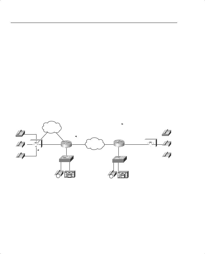
When a call is attempted at the originating gateway, the network congestion values for the IP destination are used to allow or reject the call. The network congestion values for delay, loss, or ICPIF are obtained by sending an SAA probe to the IP destination the call is trying to reach. The threshold values for rejecting a call are configured at the originating gateway. Figure 8-14 illustrates this concept.
Figure 8-14 PSTN Fallback
|
|
|
|
|
|
|
|
|
SAA Probe sent across the IP network. |
|
|
|
|
|
|
|
|
||
|
|
|
|
|
|
|
PSTN |
SAA Probe response. Congestions detected |
|
|
|
|
|
|
|
||||
|
|
|
|
|
|
|
|
|
across the WAN; ICPIF or delay/loss |
|
|
|
|
|
|
|
|||
|
|
|
|
|
|
|
|
|
exceeded threshold. |
|
|
|
|
|
|
|
|
|
|
|
|
|
|
|
|
|
R1 |
|
IP Network |
R2 |
|
|
|
|
|
|
|
|
|
|
|
|
|
|
|
|
|
|
|
|
|
|
|
|
|||||
|
|
|
|
|
|
|
|
|
|
|
|
|
|
||||||
|
|
|
|
|
|
|
|
|
|
|
|
|
|
||||||
|
|
|
|
|
|
|
|
|
|
|
|
|
|
|
|
||||
|
|
|
|
|
|
|
|
|
|
|
|
|
|
|
|
|
|
|
|
|
|
|
|
|
|
|
SW1 |
|
|
SW2 |
|
|
|
|
|
|
|
||
|
|
|
|
|
|
|
|
|
|
|
|
|
|
|
|
||||
|
|
|
|
|
|
|
|
|
|
|
|
|
|
|
|
||||
|
|
|
|
|
|
|
|
|
|
|
|
|
|
|
|
||||
Possible Destinations for Redirection: |
|
|
|
|
|
|
|
|
|
|
|
•Alternate IP Destinations
•Gateway Connection to PSTN
• Hairpin Call to PBX |
|
|
|
|
|
|
|
|
|
|
|
|
|
|
|
|
|
|
|
|
|
|
|
|
|
|
|
|
|
|
|
|
|
|
|
|
|
|
|
|
|
|
|
|
(CAS and Analog) |
|
|
|
|
|
|
|
|
|
|
|
|
|
|
IP |
|
|
|
|
IP |
|
|
|
|
|||||
|
|
|
||||||||||||
|
|
|
|
|
|
|
|
|
|
|||||
• Reject Call to PBX (ISDN) |
|
|
CallManager |
|
|
CallManager |
||||||||
• Reorder Tone |
|
|
|
|
|
|
|
|
|
|
|
|
|
|
IP Destination Caching
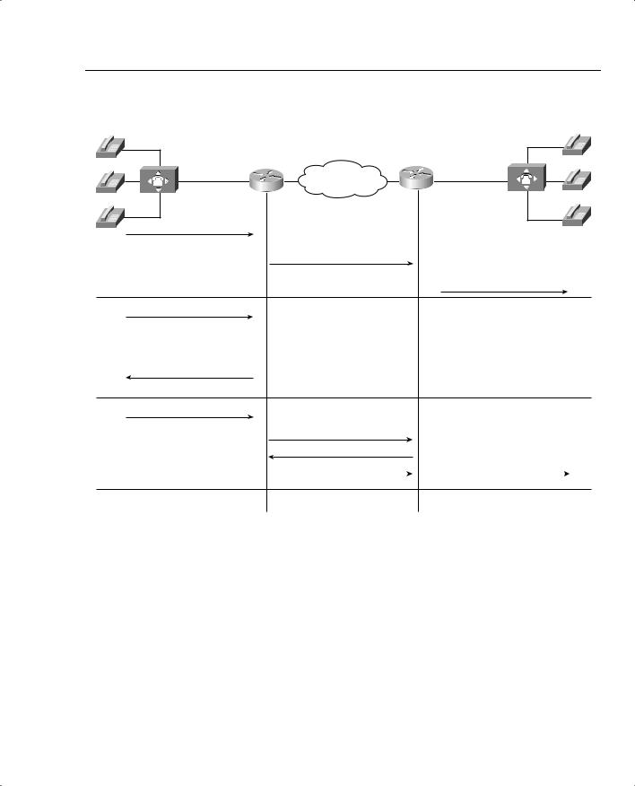
Unlike AVBO, PSTN fallback does not require the static configuration of the IP destinations. The software keeps a cache of configurable size that tracks the most recently used IP destinations to which calls were attempted. If the IP destination of a new call attempt is found in the cache, the CAC decision for the call can be made immediately. If the entry does not appear in the cache, a new probe is started and the call setup is suspended until the probe response arrives. Therefore, an extra postdial delay is imposed only for the first call to a new IP destination. Figure 8-15 illustrates these possible scenarios.

Measurement-Based Voice CAC 577
Figure 8-15 PSTN Fallback Call Setup
Call Setup
1Scenario
Call Setup
2Scenario Call Reject / Hairpin
Call Setup 3Scenario
R1 |
IP Network |
R2 |
|
Cache entry for IP address found; CAC values are acceptable.
Call Setup
Call Setup
Cache entry for IP address found; CAC values not acceptable and no secondary dial-peer exists.
Cache entry for IP address not found.
SAA Probe
SAA Response
Call Setup |
|
Call Setup |
Figure 8-15 demonstrates three possible scenarios. In all scenarios, a call setup message is send to router 1 (R1). R1 consults its cache to determine whether a path exists and, if so, that the ICPIF or delay/loss thresholds have not been exceeded. In scenario one, both conditions are true and the call setup message is forwarded to router 2 (R2) to connect the call. In scenario two, a path to the IP destination is found in cache; however, the ICPIF or loss/delay exceed the threshold for that path and the call is either rejected or hairpinned back to the origination PBX, depending on the interface type connecting the PBX with R1. In scenario three, a path to the IP destination is not found in cache. An SAA probe is sent to the IP destination to determine the ICPIF or loss/delay values. If the response shows that the thresholds have not been exceeded, the call setup message is forwarded on to router 2 (R2) to connect the call.
After an IP destination has been entered into the cache, a periodic probe with a configurable timeout value is sent to that destination to refresh the information in the cache. If no further calls

578 Chapter 8: Call Admission Control and QoS Signaling
are made to this IP destination, the entry ages out of the cache and probe traffic to that destination is discontinued. In this way, PSTN fallback dynamically adjusts the probe traffic to the IP destinations that are actively seeing call activity.
SAA Probe Format
Each probe consists of a configurable number of packets. The delay, loss, and ICPIF values entered into the cache for the IP destination are averaged from all the responses.
If an endpoint is attempting to establish a voice conversation using a G.729 or G.711 codec, the probe’s packet size emulates the codec of the requesting endpoint. Additional codecs use G.711-like probes.
The IP precedence of the probe packets can also be configured to emulate the priority of a voice packet. This parameter should be set equal to the IP precedence used for other voice media packets in the network. Typically the IP precedence value is set to 5 for voice traffic.
PSTN Fallback Configuration
PSTN fallback is configured on the originating gateway and applies only to calls initiated by the originating gateway. Inbound call attempts are not considered. PSTN fallback is configured at the global level and therefore applies to all outbound calls attempted by the gateway. You cannot selectively apply PSTN fallback to calls initiated by certain PSTN/PBX interfaces. The SAA responder feature is configured on the destination node, also referred to as the terminating gateway.
To apply PSTN fallback, enter the following global configuration commands:
•
•
Originating gateway: the call fallback command
Destination node: the rtr responder command
Table 8-11 lists the options and default values of the call fallback command.
Table 8-11 Call Fallback Command
Call Fallback Command |
|
Default |
Keyword |
Description |
Value |
|
|
|
cache-size x |
Specifies the call fallback cache size for network traffic |
128 |
|
probe entries. |
|
|
|
|
cache-timeout x |
Specifies the time after which the cache entries of |
600s |
|
network conditions are purged. |
|
|
|
|
instantaneous-value-weight x |
Specifies that the call fallback subsystem take an average |
66 |
|
from the last two cache entries for call requests. |
|
|
|
|
jitter-probe num-packets x |
Specifies the number of packets in a jitter probe used to |
15 |
|
determine network conditions. |
|
|
|
|

Measurement-Based Voice CAC 579
Table 8-11 Call Fallback Command (Continued)
Call Fallback Command |
|
Default |
Keyword |
Description |
Value |
|
|
|
jitter-probe precedence x |
Specifies the priority of the jitter-probe transmission. |
2 |
|
|
|
jitter-probe priority-queue |
Assigns a priority queue for jitter-probe transmissions. |
Off |
|
|
|
key-chain |
Specifies MD5 authentication for sending and receiving |
None |
|
SAA probes. |
|
|
|
|
map subnet |
Specifies that the call fallback router keep a cache table |
None |
|
by subnet addresses of distances for several destination |
|
|
peers sitting behind the router. |
|
|
|
|
probe-timeout x |
Sets the timeout for an SAA probe for call fallback |
30s |
|
purposes. |
|
|
|
|
threshold delay x loss y |
Specifies that the call fallback threshold use only packet |
None |
|
delay and loss values. |
|
|
|
|
Icpif x |
Specifies that the call fallback use the ICPIF threshold. |
10 |
|
|
|
Examples 8-13 and 8-14 demonstrate PSTN fallback between a host and remote site. SAA is configured on the remote site to answer the probes from the host site. When the number 1234 is dialed from the host site and congestion is observed on the link between the host site and the remote site, the call is redirected to port 3/0:23 and connected to the remote site over the PSTN.
Probes are sent every 20 seconds with 15 packets in each probe. The probes share the priority queue with the other voice packets. The delay and loss threshold command is configured with a delay threshold of 150 ms and a loss threshold of 5 percent and the cache aging timeout is configured for 10,000 seconds.
Example 8-13 shows the configuration for the host site router.
Example 8-13 Call Fallback Host Site Configuration
Hostname Host-Site
!
call fallback probe-timeout 20
call fallback threshold delay 150 loss 5 call fallback jitter-probe num-packets 15 call fallback jitter-probe priority-queue call fallback cache-timeout 10000
call fallback active
!
interface Serial1/0
ip address 10.1.1.1 255.255.255.0
!
interface Serial3/0:23 no ip address
continues

580 Chapter 8: Call Admission Control and QoS Signaling
Example 8-13 Call Fallback Host Site Configuration (Continued)
no logging event link-status isdn switch-type primary-ni isdn incoming-voice voice no cdp enable
!
voice-port 3/0:23
!
dial-peer voice 100 voip destination-pattern 12.. preference 1
session target ipv4:10.1.1.2
!
dial-peer voice 10 pots destination-pattern 12.. preference 2
port 3/0:23
!Adds prefix in front of the dialed number route over the PSTN prefix 9140455512
!
dial-peer voice 20 pots destination-pattern 9T port 3/0:23
Example 8-14 shows the configuration for the remote site router.
Example 8-14 Call Fallback Remote Site Configuration for Host Name Remote Site
!
interface Serial1/0
ip address 10.1.1.2 255.255.255.0
!
interface Serial3/0:23 no ip address
no logging event link-status isdn switch-type primary-ni isdn incoming-voice voice no cdp enable
!
voice-port 3/0:23
!
dial-peer voice 100 voip destination-pattern 5...
preference 1
session target ipv4:10.1.1.1
!
dial-peer voice 10 pots destination-pattern 5...
preference 2 port 3/0:23