

544 Chapter 8: Call Admission Control and QoS Signaling
Foundation Topics
Call Admission Control Overview
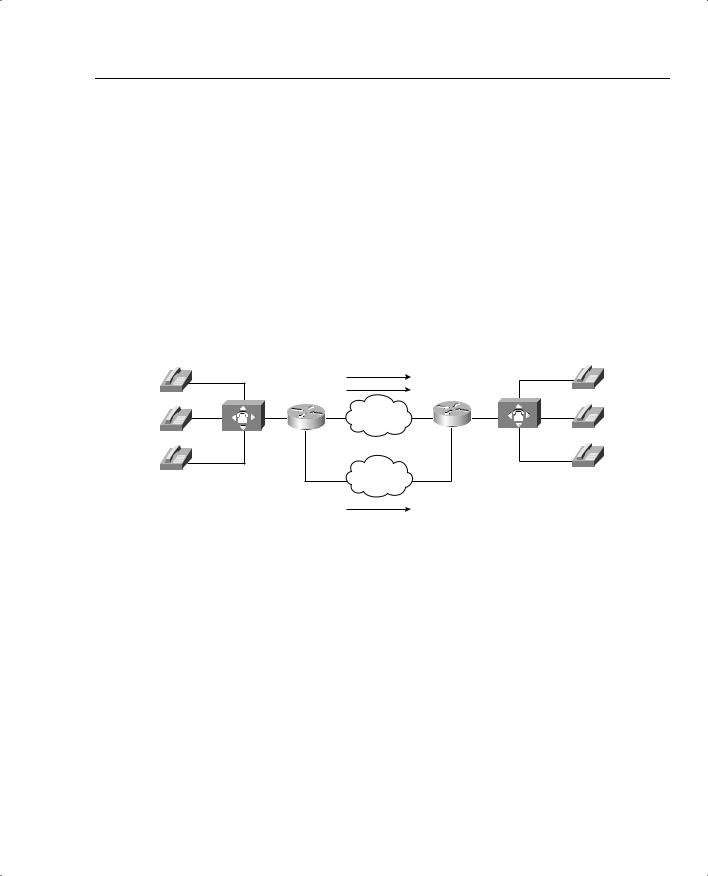
Call admission control (CAC) mechanisms extend the capabilities of other quality of service (QoS) methods to ensure that voice traffic across the network link does not suffer latency, jitter, or packet loss that can be introduced by the addition of other voice traffic. CAC achieves this task by determining whether the required network resources are available to provide suitable QoS for a new call, before the new call is placed. Simply put, CAC protects voice conversations from other voice conversations. Figure 8-1 demonstrates the need for CAC. In this example, if the WAN link between the two private branch exchanges (PBXs) has sufficient bandwidth to carry only two Voice over IP (VoIP) calls, admitting the third call will impair the voice quality of all three calls.
Figure 8-1 VoIP Network Without CAC
IP Network Supports 2 Calls Max!
|
Call 1 |
|
|
Call 2 |
|
R1 |
IP Network |
R2 |
|
Call 3
The Third Call Degrades Voice Quality for All Calls
Similar to the earlier HOV example, the reason for this impairment is that the employed queuing mechanisms do not provide CAC. If packets exceeding the configured or budgeted rate are received in the priority queue, in this case more than two calls, these packets are just tail dropped from the priority queue. There is no capability in the queuing mechanisms to distinguish which IP packet belongs to which voice call. As mentioned in Chapter 4, “Congestion Management,” both Low Latency Queuing (LLQ) and IP RTP Priority police traffic inside the low-latency queue when the interface is congested, so any packet exceeding the configured rate within a certain period of time is dropped. In this event, all three calls will experience packet loss and jitter, which can be perceived as clipped speech or dropped syllables in each of the voice conversations.
The addition of CAC preserves the quality of the voice conversations in progress by rejecting a new call when insufficient network resources are available to allow the new call to proceed.
Call Admission Control Overview 545
Call Rerouting Alternatives
If a call has been rejected by a CAC mechanism due to insufficient network resources, there needs to be some alternate route in place to establish the call. In the absence of an alternate route, the caller will hear a reorder tone. The reorder tone is called a fast-busy tone in North America, and is known as overflow tone or equipment busy in other parts of the world. This tone is often intercepted by Public Switched Telephone Network (PSTN) switches or PBXs with an announcement such as “All circuits are busy, please try your call again later.”
Figure 8-2 illustrates an originating gateway, router R1, with CAC configured to reroute a call to the PSTN when insufficient network resources are available to route the call over the WAN link.
Figure 8-2 Legacy VoIP Network with CAC
IP Network Supports 2 Calls Max!
|
Call 1 |
|
|
Call 2 |
|
R1 |
IP Network |
R2 |
|
PSTN
Call 3
CAC Reroutes the Third Call Through the PSTN
In a legacy VoIP environment, also known as a toll-bypass environment, the configuration of the originating gateway determines where the call is rerouted. The following scenarios can be configured:
•Alternate WAN path—The call can be rerouted to take advantage of an alternate WAN link if such a path exists. This is accomplished by configuring a second VoIP dial peer with a higher preference than the primary VoIP dial peer. When the primary VoIP dial peer rejects the call, the second VoIP dial peer is matched, causing the call to use the alternate WAN link.
•Alternate PSTN path—The call can be rerouted to take advantage of an alternate timedivision multiplexing (TDM) network path if such a path exists. This is accomplished by configuring a plain old telephone service (POTS) dial peer and a physical TDM interface connected to a PSTN circuit or a PBX interface. When the primary VoIP dial peer rejects the call, the POTS dial peer is matched, causing the call to use the alternate PSTN link.

546Chapter 8: Call Admission Control and QoS Signaling
•Return to originating switch—The call can be returned to the originating TDM switch to leverage any existing rerouting capabilities within the originating switch. How this is accomplished depends on the interface type providing the connectivity between the originating switch and originating gateway:
—Common channel signaling (CCS): CCS trunks, such as Primary Rate ISDN (PRI) and Basic Rate ISDN (BRI), separate the signaling and voice conversations into two distinct channels. The signaling channel is referred to as the
D channel, and the voice conversation is known as the bearer channel. This separation of channels gives the originating gateway the capability to alert the originating switch in the event that insufficient network resources are available to place the call. This allows the originating switch to tear down the connection and resume handling of the call with an alternate path.
—Channel-associated signaling (CAS): CAS trunks, such as E&M and T1 CAS, combine the signaling and voice conversations in a single channel. The originating gateway has no means of alerting the originating switch if insufficient network resources are available to place the call. For the originating gateway to return the initial call to the originating switch, a second channel must be used to reroute the voice conversation back to the originating switch. This process, known as hairpinning, causes the initial call channel and the second rerouted channel to remain active during the life of the voice conversation.
An IP telephony environment uses much of the same concepts as a legacy VoIP environment to handle CAC. However, an additional layer of control is added by the introduction of the CallManager cluster, which keeps the state of voice gateways and the availability of network resources in a central location. In an IP telephony environment, the configuration of the CallManager cluster in conjunction with the voice gateways determines whether, and where, a call is rerouted in the event of a reject due to insufficient network resources.
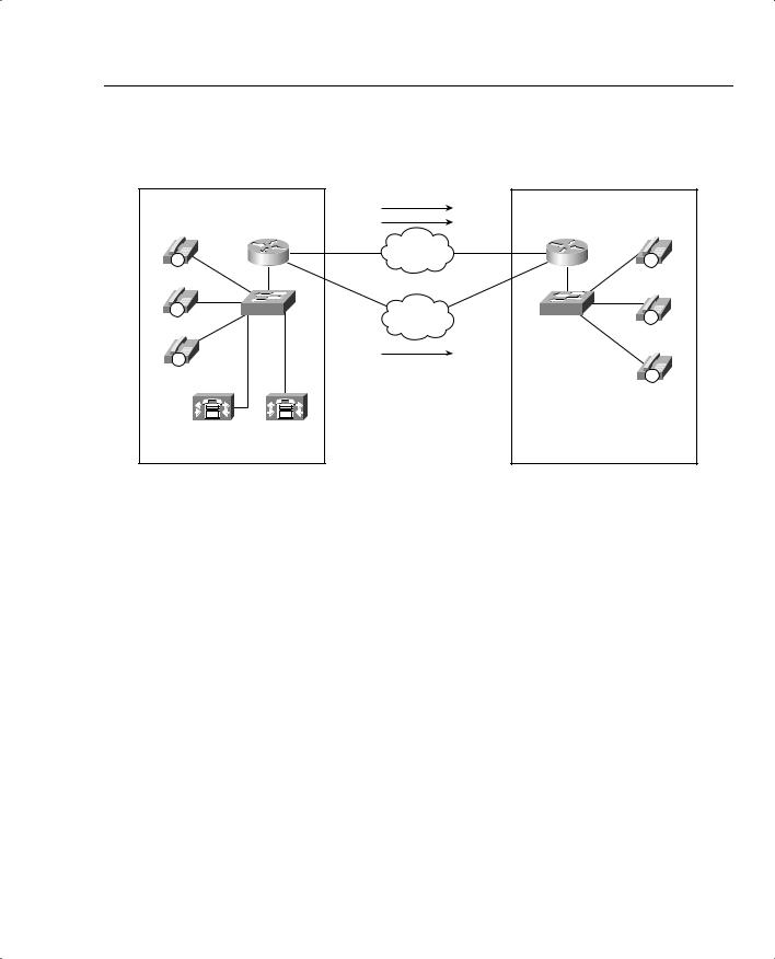
Figure 8-3 illustrates an IP telephony solution with CAC configured to reroute a call to the PSTN when there is insufficient network resources to route the call over the WAN link.
Bandwidth Engineering
To successfully implement CAC mechanisms in your packet network, you must begin with a clear understanding of the bandwidth required by each possible call that can be placed. In
Chapter 7, “Link-Efficiency Tools,” you learned about bandwidth requirements for two of the most popular codecs deployed in converged networks, G.711 and G.729.
The G.711 codec specification carries an uncompressed 64-kbps payload stream, known in the traditional telephony world as pulse code modulation (PCM). G.711 offers toll-quality voice conversations at the cost of bandwidth consumption. The G.711 codec is ideally suited for the situation in which bandwidth is abundant and call quality is the primary driver, such as in LAN environments.
Call Admission Control Overview 547
Figure 8-3 IP Telephony Network with CAC |
|
|
||
|
|
IP Network Supports 2 Calls Max! |
|
|
Host Site |
Call 1 |
Remote Site |
||
|
|
Call 2 |
|
|
IP |
R1 |
IP Network |
R2 |
IP |
|
||||
Host Phone A |
|
|
|
Remote |
|
|
|
|
Phone A |
IP |
SW1 |
PSTN |
SW2 |
IP |
Host Phone B |
|
|
||
|
|
|
Remote |
|
|
|
|
|
|
|
|
Call 3 |
|
Phone B |
|
|
|
|
|
IP |
|
CAC Reroutes the Third Call |
|
|
Host Phone C |
|
|
IP |
|
|
|
Through the PSTN |
|
|
|
|
|
Remote |
|
|
|
|
|
|
|
|
|
|
Phone C |
CallManager |
CallManager |
|
|
|
Publisher |
Subscriber |
|
|
|
The G.729 codec specification carries a compressed 8-kbps payload stream, known in the traditional telephony world as conjugate-structure algebraic-code-excited linear-prediction
(CS-ACELP). G.729 offers a tradeoff: reduced overall bandwidth consumption with a slight reduction in voice quality. G.729 is ideally suited for the situation in which bandwidth is limited, such as in a WAN environment.
As you learned in previous chapters, several other features play a role in determining the bandwidth requirement of a voice call, including header compression, Layer 2 headers, and voice samples per packet. Voice Activation Detection (VAD) can also play a role in the bandwidth required by each call. VAD can be used to reduce the packet payload size by transmitting 2 bytes of payload during silent times rather than the full payload size. For example, the payload on a single G.711 packet using Cisco defaults is 160 bytes. VAD can reduce the size of the payload to 2 bytes during silent times in the conversations. Although VAD can offer bandwidth savings, Cisco recommends that VAD be disabled due to the possible voice-quality issues that it may induce. For the purposes of bandwidth engineering, VAD should not be taken into account.
Table 8-2 illustrates a few of the possible G.711 and G.729 bandwidth requirements.

548 Chapter 8: Call Admission Control and QoS Signaling
Table 8-2 |
Bandwidth Requirements |
|
|
|
|
||
|
|
|
|
|
|
|
|
|
|
Payload |
|
|
|
Packets |
|
|
|
per |
IP/UDP/RTP |
L2 Header |
L2 Header |
per |
Bandwidth |
|
Codec |
Packet |
Header Size |
Type |
Size |
Second |
per Call |
|
|
|
|
|
|
|
|
|
G.711 |
160 bytes |
40 bytes |
Ethernet |
14 bytes |
50 pps |
85.6 kbps |
|
|
|
|
|
|
|
|
|
G.711 |
240 bytes |
40 bytes |
Ethernet |
14 bytes |
33 pps |
77.6 kbps |
|
|
|
|
|
|
|
|
|
G.711 |
160 bytes |
40 bytes |
MLPPP/FR |
6 bytes |
50 pps |
82.4 kbps |
|
|
|
|
|
|
|
|
|
G.711 |
160 bytes |
2 bytes (cRTP) |
MLPPP/FR |
6 bytes |
50 pps |
67.2 kbps |
|
|
|
|
|
|
|
|
|
G.729 |
20 bytes |
40 bytes |
Ethernet |
14 bytes |
50 pps |
29.6 kbps |
|
|
|
|
|
|
|
|
|
G.729 |
20 bytes |
40 bytes |
MLPPP/FR |
6 bytes |
50 pps |
26.4 kbps |
|
|
|
|
|
|
|
|
|
G.729 |
30 bytes |
40 bytes |
MLPPP/FR |
6 bytes |
33 pps |
20 kbps |
|
|
|
|
|
|
|
|
|
G.729 |
20 bytes |
2 bytes (cRTP) |
MLPPP/FR |
6 bytes |
50 pps |
11.2 kbps |
|
|
|
|
|
|
|
|
*For DQOS test takers: These numbers are extracted from the DQOS course, so you can study those numbers. Note, however, that the numbers in the table and following examples do not include the L2 trailer overhead. Go to www.cisco.com, and search for “QoS SRND” for a document that provides some great background on QoS, and the bandwidth numbers that include data-link overhead.
The formula used to calculate the bandwidth for this combination of factors is as follows: Bandwidth per call = (Payload + IP/UDP/RTP + L2) * 8 * pps
For example, using G.729 @ 50 pps over Frame Relay without header compression results in the following calculation:
Bandwidth per call = (20 + 40 + 6) * 8 * 50 = 26.4 kbps
For example, using G.711 @ 50 pps over Ethernet without header compression results in the following calculation:
Bandwidth per call = (160 + 40 + 14) * 8 * 50 = 85.6 kbps
The elements in the bandwidth per call formula correspond to the following values:
•Payload—Payload size per packet depends on the codec selected and the number of voice samples in each packet. One voice sample represents 10 ms of speech. By default, Cisco includes two of these samples in each packet, transmitting 20 ms of speech in each packet. This means that there must be 50 packets per second to maintain a full second of voice conversation, as shown in the following:
20 ms * 50 pps = 1 second of voice conversation

Call Admission Control Overview 549
After the number of samples per packet and packets per second has been determined, the payload size per packet is easily calculated by using the following formula:
Codec @ pps = (Codec payload bandwidth) / (Number of bits in a byte) / (Packets per second)
For example, the following shows a G.711 voice conversation using 50 pps:
G.711 @ 50 pps = 64 kbps / 8 bits / 50 pps = 160 bytes
For example, the following shows a G.711 voice conversation using 33 pps:
G.711 @ 33 pps = 64 kbps / 8 bits / 33 pps = 240 bytes
For example, the following shows a G.729 voice conversation using 50 pps:
G.729 @ 50 pps = 8 kbps / 8 bits / 50 pps = 20 bytes
For example, the following shows a G.729 voice conversation using 33 pps:
G.729 @ 33.334 pps = 8 kbps / 8 bits / 33.334 pps = 30 bytes
•IP/UDP/RTP headers—This is the combination of the IP header, UDP header, and RTP header overhead expressed in bytes. Without compression, this combination equals 40 bytes.
•Layer 2 header type—The Layer 2 transport technologies have the following header overheads:
—Ethernet: 14 bytes
—PPP and MLP: 6 bytes
—Frame Relay: 6 bytes
—ATM (AAL5): 5 bytes (plus cell fill waste)
—MLP over Frame Relay: 14 bytes
—MLP over ATM (AAL5): 5 bytes for every ATM cell + 20 bytes for the MLP and AAL5 encapsulation of the IP packet
Figure 8-4 illustrates the packet structure of the Layer 2 and IP/UDP/RTP headers and the payload for a voice packet.
Figure 8-4 Voice Packet Structure
Layer 2 |
IP |
UDP |
RTP |
Payload of Speech Samples |
Variable |
|
|
|
Variable Size Based on Codec |
Size |
20 |
8 |
12 |
Selection and Number of |
Based on |
Bytes |
Bytes |
Bytes |
Speech Samples Included |
Layer 2 |
|
|
|
|
Protocol |
|
|
|
|
|
|
|
|
|

550Chapter 8: Call Admission Control and QoS Signaling
•8—Each byte has 8 bits.
•pps—The number of packets per second required to deliver a full second of a voice conversation. This value depends on the number of 10-ms samples within each packet. By default Cisco includes two 10-ms samples in each packet, transmitting 20 ms of sampled speech in each packet. If the number of samples per packet changes, the packets per second required to deliver a full second of voice conversation changes as well. If the packets per second increase, the overhead associated with the voice conversation increases, which requires additional bandwidth to deliver the same payload. Likewise, if the packets per second decrease, the overhead associated with the voice conversation decreases, which requires less bandwidth to deliver the same payload. The following calculations demonstrate the relationship between the packets per second and the samples included in each packet:
—10 ms * 100 pps = 1 second of voice conversation
—20 ms * 50 pps = 1 second of voice conversation
—30 ms * 33 pps = 1 second of voice conversation
Armed with this information you can begin to build out bandwidth requirements based on the network infrastructure, codec, packet payload, and the number of simultaneous calls that need to be supported.
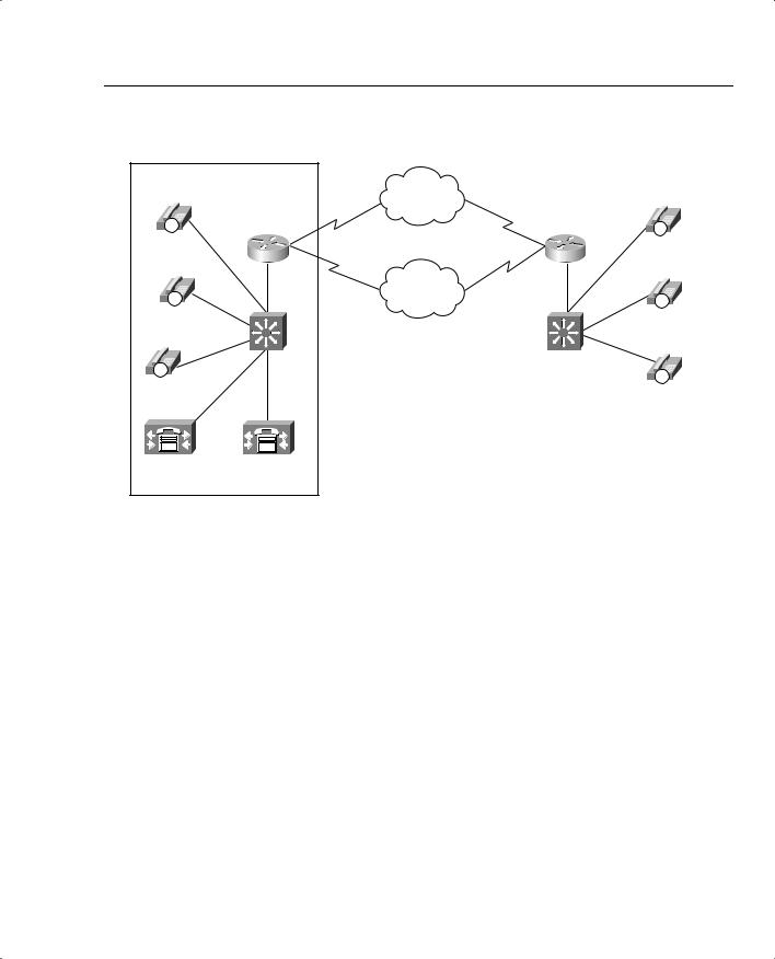
Figure 8-5 illustrates a small IP telephony network configured to use the G.711 codec @ 50 pps for all calls placed over the LAN; the G.729 codec @ 50 pps is used for all calls placed over the WAN.
In this example, RTP header compression and VAD are not in use and the Cisco default of 50 packets per second is assumed. A call from Host B phone to Host C phone across the switched LAN infrastructure consumes 85.6 kbps of bandwidth, as shown in the following equation:
(160 + 40 + 14) * 8 * 50 = 85.6 kbps
A call placed from Host A phone across the WAN infrastructure to Remote A phone in this scenario requires 26.4 kbps, as shown in the following equation:
(20 + 40 + 6) * 8 * 50 = 26.4 kbps
Assuming that you must allow 6 simultaneous calls across this WAN link at any given time, 158.4 kbps of WAN bandwidth is required to support the voice conversations, as shown in the following equation:
6 * 26.4 kbps = 158.4 kbps
Call Admission Control Overview 551
Figure 8-5 Bandwidth Considerations |
|
|
|
Host Site |
Remote Site |
||
|
|
Frame Relay |
|
IP |
Voice Gateway |
Voice Gateway |
IP |
Host Phone |
|
|
Remote |
A |
|
|
Phone A |
IP |
|
PSTN |
IP |
|
|
||
Host Phone |
|
|
Remote |
B |
|
|
Phone B |
IP |
Catalyst |
Catalyst |
|
Switch |
Switch |
IP |
|
|
|
|
|
Host Phone |
|
|
Remote |
C |
|
|
Phone C |
CallManager |
CallManager |
|
|
Publisher |
Subscriber |
|
|
Host Phone B Uses G.711 Across |
Host Phone A Uses G.729 Across |
||
Ethernet to Call Host Phone C |
the Frame Relay Cloud to Call |
||
|
|
Remote Phone A. |
|
Assuming that you must provide for a guaranteed minimum of 256 kbps for data traffic, the total circuit bandwidth requirements can be derived from the following formula:
(Number of calls desired * bandwidth per call) + (Total data requirements)
or
(6 calls * 26.4 kbps) + 256 kbps = 414.4 kbps
Examining circuit speeds available today, a 512-kbps link can be used for this IP telephony network to meet the assumed voice and data requirements for 414.4 kbps. The remaining 97.6 kbps can be used for additional overhead, such as routing protocols.
Table 8-3 illustrates the relationship between codec, header compression, number of simultaneous calls, and the minimum bandwidth required for data traffic. Although the number of simultaneous calls, packet payload, and data requirements remained constant in this example, the codec selection and header compression varied the total circuit bandwidth requirements significantly.