
- •QoS Overview
- •“Do I Know This Already?” Quiz
- •QoS: Tuning Bandwidth, Delay, Jitter, and Loss Questions
- •Foundation Topics
- •QoS: Tuning Bandwidth, Delay, Jitter, and Loss
- •Bandwidth
- •The clock rate Command Versus the bandwidth Command
- •QoS Tools That Affect Bandwidth
- •Delay
- •Serialization Delay
- •Propagation Delay
- •Queuing Delay
- •Forwarding Delay
- •Shaping Delay
- •Network Delay
- •Delay Summary
- •QoS Tools That Affect Delay
- •Jitter
- •QoS Tools That Affect Jitter
- •Loss
- •QoS Tools That Affect Loss
- •Summary: QoS Characteristics: Bandwidth, Delay, Jitter, and Loss
- •Voice Basics
- •Voice Bandwidth Considerations
- •Voice Delay Considerations
- •Voice Jitter Considerations
- •Voice Loss Considerations
- •Video Basics
- •Video Bandwidth Considerations
- •Video Delay Considerations
- •Video Jitter Considerations
- •Video Loss Considerations
- •Comparing Voice and Video: Summary
- •IP Data Basics
- •Data Bandwidth Considerations
- •Data Delay Considerations
- •Data Jitter Considerations
- •Data Loss Considerations
- •Comparing Voice, Video, and Data: Summary
- •Foundation Summary
- •QoS Tools and Architectures
- •“Do I Know This Already?” Quiz
- •QoS Tools Questions
- •Differentiated Services Questions
- •Integrated Services Questions
- •Foundation Topics
- •Introduction to IOS QoS Tools
- •Queuing
- •Queuing Tools
- •Shaping and Policing
- •Shaping and Policing Tools
- •Congestion Avoidance
- •Congestion-Avoidance Tools
- •Call Admission Control and RSVP
- •CAC Tools
- •Management Tools
- •Summary
- •The Good-Old Common Sense QoS Model
- •GOCS Flow-Based QoS
- •GOCS Class-Based QoS
- •The Differentiated Services QoS Model
- •DiffServ Per-Hop Behaviors
- •The Class Selector PHB and DSCP Values
- •The Assured Forwarding PHB and DSCP Values
- •The Expedited Forwarding PHB and DSCP Values
- •The Integrated Services QoS Model
- •Foundation Summary
- •“Do I Know This Already?” Quiz Questions
- •CAR, PBR, and CB Marking Questions
- •Foundation Topics
- •Marking
- •IP Header QoS Fields: Precedence and DSCP
- •LAN Class of Service (CoS)
- •Other Marking Fields
- •Summary of Marking Fields
- •Class-Based Marking (CB Marking)
- •Network-Based Application Recognition (NBAR)
- •CB Marking show Commands
- •CB Marking Summary
- •Committed Access Rate (CAR)
- •CAR Marking Summary
- •Policy-Based Routing (PBR)
- •PBR Marking Summary
- •VoIP Dial Peer
- •VoIP Dial-Peer Summary
- •Foundation Summary
- •Congestion Management
- •“Do I Know This Already?” Quiz
- •Queuing Concepts Questions
- •WFQ and IP RTP Priority Questions
- •CBWFQ and LLQ Questions
- •Comparing Queuing Options Questions
- •Foundation Topics
- •Queuing Concepts
- •Output Queues, TX Rings, and TX Queues
- •Queuing on Interfaces Versus Subinterfaces and Virtual Circuits (VCs)
- •Summary of Queuing Concepts
- •Queuing Tools
- •FIFO Queuing
- •Priority Queuing
- •Custom Queuing
- •Weighted Fair Queuing (WFQ)
- •WFQ Scheduler: The Net Effect
- •WFQ Scheduling: The Process
- •WFQ Drop Policy, Number of Queues, and Queue Lengths
- •WFQ Summary
- •Class-Based WFQ (CBWFQ)
- •CBWFQ Summary
- •Low Latency Queuing (LLQ)
- •LLQ with More Than One Priority Queue
- •IP RTP Priority
- •Summary of Queuing Tool Features
- •Foundation Summary
- •Conceptual Questions
- •Priority Queuing and Custom Queuing
- •CBWFQ, LLQ, IP RTP Priority
- •Comparing Queuing Tool Options
- •“Do I Know This Already?” Quiz
- •Shaping and Policing Concepts Questions
- •Policing with CAR and CB Policer Questions
- •Shaping with FRTS, GTS, DTS, and CB Shaping
- •Foundation Topics
- •When and Where to Use Shaping and Policing
- •How Shaping Works
- •Where to Shape: Interfaces, Subinterfaces, and VCs
- •How Policing Works
- •CAR Internals
- •CB Policing Internals
- •Policing, but Not Discarding
- •Foundation Summary
- •Shaping and Policing Concepts
- •“Do I Know This Already?” Quiz
- •Congestion-Avoidance Concepts and RED Questions
- •WRED Questions
- •FRED Questions
- •Foundation Topics
- •TCP and UDP Reactions to Packet Loss
- •Tail Drop, Global Synchronization, and TCP Starvation
- •Random Early Detection (RED)
- •Weighted RED (WRED)
- •How WRED Weights Packets
- •WRED and Queuing
- •WRED Summary
- •Flow-Based WRED (FRED)
- •Foundation Summary
- •Congestion-Avoidance Concepts and Random Early Detection (RED)
- •Weighted RED (WRED)
- •Flow-Based WRED (FRED)
- •“Do I Know This Already?” Quiz
- •Compression Questions
- •Link Fragmentation and Interleave Questions
- •Foundation Topics
- •Payload and Header Compression
- •Payload Compression
- •Header Compression
- •Link Fragmentation and Interleaving
- •Multilink PPP LFI
- •Maximum Serialization Delay and Optimum Fragment Sizes
- •Frame Relay LFI Using FRF.12
- •Choosing Fragment Sizes for Frame Relay
- •Fragmentation with More Than One VC on a Single Access Link
- •FRF.11-C and FRF.12 Comparison
- •Foundation Summary
- •Compression Tools
- •LFI Tools
- •“Do I Know This Already?” Quiz
- •Foundation Topics
- •Call Admission Control Overview
- •Call Rerouting Alternatives
- •Bandwidth Engineering
- •CAC Mechanisms
- •CAC Mechanism Evaluation Criteria
- •Local Voice CAC
- •Physical DS0 Limitation
- •Max-Connections
- •Voice over Frame Relay—Voice Bandwidth
- •Trunk Conditioning
- •Local Voice Busyout
- •Measurement-Based Voice CAC
- •Service Assurance Agents
- •SAA Probes Versus Pings
- •SAA Service
- •Calculated Planning Impairment Factor
- •Advanced Voice Busyout
- •PSTN Fallback
- •SAA Probes Used for PSTN Fallback
- •IP Destination Caching
- •SAA Probe Format
- •PSTN Fallback Scalability
- •PSTN Fallback Summary
- •Resource-Based CAC
- •Resource Availability Indication
- •Gateway Calculation of Resources
- •RAI in Service Provider Networks
- •RAI in Enterprise Networks
- •RAI Operation
- •RAI Platform Support
- •Cisco CallManager Resource-Based CAC
- •Location-Based CAC Operation
- •Locations and Regions
- •Calculation of Resources
- •Automatic Alternate Routing
- •Location-Based CAC Summary
- •Gatekeeper Zone Bandwidth
- •Gatekeeper Zone Bandwidth Operation
- •Single-Zone Topology
- •Multizone Topology
- •Zone-per-Gateway Design
- •Gatekeeper in CallManager Networks
- •Zone Bandwidth Calculation
- •Gatekeeper Zone Bandwidth Summary
- •Integrated Services / Resource Reservation Protocol
- •RSVP Levels of Service
- •RSVP Operation
- •RSVP/H.323 Synchronization
- •Bandwidth per Codec
- •Subnet Bandwidth Management
- •Monitoring and Troubleshooting RSVP
- •RSVP CAC Summary
- •Foundation Summary
- •Call Admission Control Concepts
- •Local-Based CAC
- •Measurement-Based CAC
- •Resources-Based CAC
- •“Do I Know This Already?” Quiz
- •QoS Management Tools Questions
- •QoS Design Questions
- •Foundation Topics
- •QoS Management Tools
- •QoS Device Manager
- •QoS Policy Manager
- •Service Assurance Agent
- •Internetwork Performance Monitor
- •Service Management Solution
- •QoS Management Tool Summary
- •QoS Design for the Cisco QoS Exams
- •Four-Step QoS Design Process
- •Step 1: Determine Customer Priorities/QoS Policy
- •Step 2: Characterize the Network
- •Step 3: Implement the Policy
- •Step 4: Monitor the Network
- •QoS Design Guidelines for Voice and Video
- •Voice and Video: Bandwidth, Delay, Jitter, and Loss Requirements
- •Voice and Video QoS Design Recommendations
- •Foundation Summary
- •QoS Management
- •QoS Design
- •“Do I Know This Already?” Quiz
- •Foundation Topics
- •The Need for QoS on the LAN
- •Layer 2 Queues
- •Drop Thresholds
- •Trust Boundries
- •Cisco Catalyst Switch QoS Features
- •Catalyst 6500 QoS Features
- •Supervisor and Switching Engine
- •Policy Feature Card
- •Ethernet Interfaces
- •QoS Flow on the Catalyst 6500
- •Ingress Queue Scheduling
- •Layer 2 Switching Engine QoS Frame Flow
- •Layer 3 Switching Engine QoS Packet Flow
- •Egress Queue Scheduling
- •Catalyst 6500 QoS Summary
- •Cisco Catalyst 4500/4000 QoS Features
- •Supervisor Engine I and II
- •Supervisor Engine III and IV
- •Cisco Catalyst 3550 QoS Features
- •Cisco Catalyst 3524 QoS Features
- •CoS-to-Egress Queue Mapping for the Catalyst OS Switch
- •Layer-2-to-Layer 3 Mapping
- •Connecting a Catalyst OS Switch to WAN Segments
- •Displaying QoS Settings for the Catalyst OS Switch
- •Enabling QoS for the Catalyst IOS Switch
- •Enabling Priority Queuing for the Catalyst IOS Switch
- •CoS-to-Egress Queue Mapping for the Catalyst IOS Switch
- •Layer 2-to-Layer 3 Mapping
- •Connecting a Catalyst IOS Switch to Distribution Switches or WAN Segments
- •Displaying QoS Settings for the Catalyst IOS Switch
- •Foundation Summary
- •LAN QoS Concepts
- •Catalyst 6500 Series of Switches
- •Catalyst 4500/4000 Series of Switches
- •Catalyst 3550/3524 Series of Switches
- •QoS: Tuning Bandwidth, Delay, Jitter, and Loss
- •QoS Tools
- •Differentiated Services
- •Integrated Services
- •CAR, PBR, and CB Marking
- •Queuing Concepts
- •WFQ and IP RTP Priority
- •CBWFQ and LLQ
- •Comparing Queuing Options
- •Conceptual Questions
- •Priority Queuing and Custom Queuing
- •CBWFQ, LLQ, IP RTP Priority
- •Comparing Queuing Tool Options
- •Shaping and Policing Concepts
- •Policing with CAR and CB Policer
- •Shaping with FRTS, GTS, DTS, and CB Shaping
- •Shaping and Policing Concepts
- •Congestion-Avoidance Concepts and RED
- •WRED
- •FRED
- •Congestion-Avoidance Concepts and Random Early Detection (RED)
- •Weighted RED (WRED)
- •Flow-Based WRED (FRED)
- •Compression
- •Link Fragmentation and Interleave
- •Compression Tools
- •LFI Tools
- •Call Admission Control Concepts
- •Local-Based CAC
- •Measurement-Based CAC
- •Resources-Based CAC
- •QoS Management Tools
- •QoS Design
- •QoS Management
- •QoS Design
- •LAN QoS Concepts
- •Catalyst 6500 Series of Switches
- •Catalyst 4500/4000 Series of Switches
- •Catalyst 3550/3524 Series of Switches
- •Foundation Topics
- •QPPB Route Marking: Step 1
- •QPPB Per-Packet Marking: Step 2
- •QPPB: The Hidden Details
- •QPPB Summary
- •Flow-Based dWFQ
- •ToS-Based dWFQ
- •Distributed QoS Group–Based WFQ
- •Summary: dWFQ Options

QoS: Tuning Bandwidth, Delay, Jitter, and Loss 13
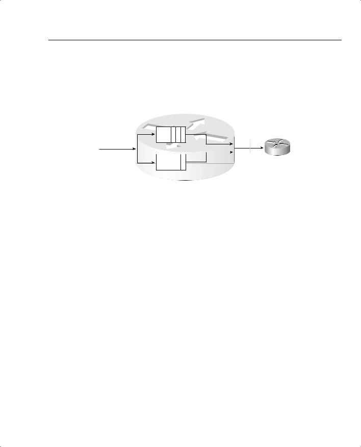
minimum amount of bandwidth to a particular queue. Figure 1-4, for example, shows a twoqueue system. The first queue gets 25 percent of the bandwidth on the link, and the second queue gets 75 percent of the bandwidth.
Figure 1-4 Bandwidth Reservation Using Queuing
4 X 1500
Byte Packets
R1
Output Queue |
125% |
3 2 1 |
Bandwidth |
|
Output Queue |
2 |
|
R2 |
|
|
|||
|
|
|
4 75% Bandwidth
With regard to Cisco IOS Software queuing tools that reserve bandwidth, if both queues have packets waiting, the algorithm takes packets such that, over time, each queue gets its configured percentage of the link bandwidth. If only one queue has packets waiting, that queue gets more than its configured amount of bandwidth for that short period.
Although adding more bandwidth always helps, the tools summarized in Table 1-3 do help to improve the efficient utilization of bandwidth in a network.
Table 1-3 QoS Tools That Affect Bandwidth
Type of QoS Tool |
How It Affects Bandwidth |
|
|
Compression |
Compresses either payload or headers, reducing overall number of bits |
|
required to transmit the data |
|
|
CAC |
Reduces overall load introduced into the network by rejecting new voice |
|
and video calls |
|
|
Queuing |
Can be used to reserve minimum amounts of bandwidth for particular |
|
types of packets |
|
|
Delay
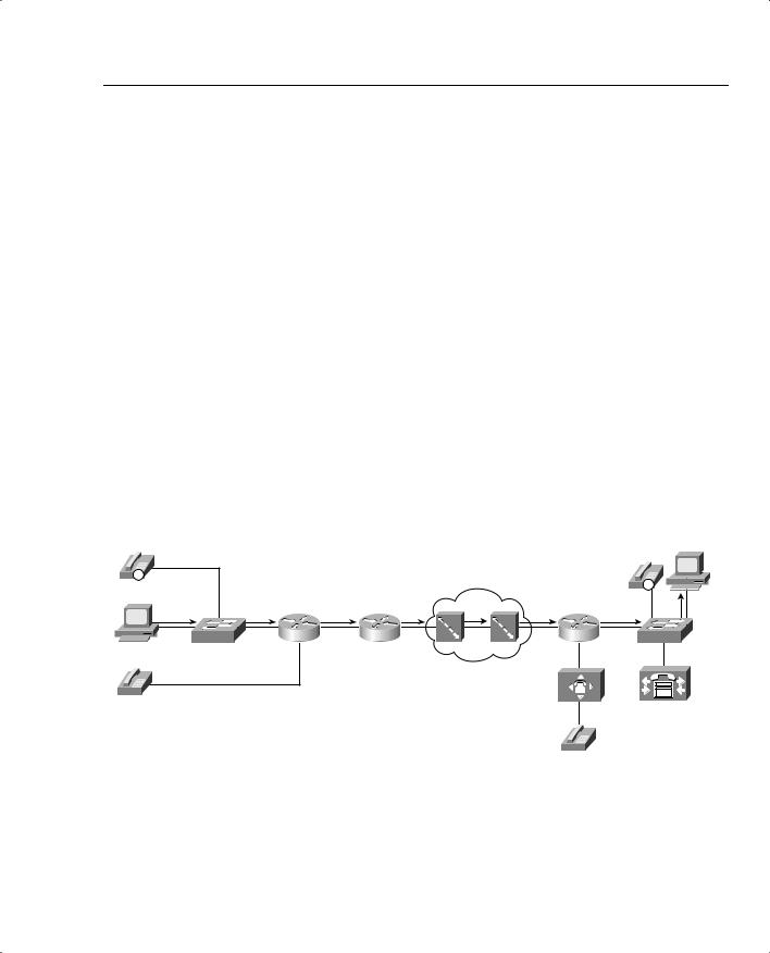
All packets in a network experience some delay between when the packet is first sent and when it arrives at its destination. Most of the concepts behind QoS mechanisms relate in some way to delay. Therefore, a deeper look into delay is useful. Take a look at Figure 1-5; this sample network is used often in this book.

14 Chapter 1: QoS Overview |
|
|
|
|
|
|
|
|
|
Figure 1-5 Sample Network for Discussion of Delay |
|
|
|
|
|
||||
|
|
|
|
|
|
|
|
|
Server 1 |
IP |
|
|
|
|
|
|
|
|
|
|
|
|
|
|
|
|
|
|
IP |
Hannah |
|
|
|
|
|
|
|
|
|
|
|
|
|
|
|
|
|
|
FA0/0 |
SW1 |
R1 |
s0 |
s0 |
R2 |
s1 |
T1 |
s0/0 |
R3 |
SW2 |
201
301
At what points will delay occur in this network? Well, at all points, in actuality. At some points in the network, the delay is so small that it can just be ignored for practical purposes. In other cases, the delay is significant, but there is nothing you can do about it! For a fuller understanding, consider the following types of delay:
•
•
•
•
•
•
•
•
Serialization delay (fixed)
Propagation delay (fixed)
Queuing delay (variable)
Forwarding/processing delay (variable)
Shaping delay (variable)
Network delay (variable)
Codec delay (fixed)
Compression delay (variable)
Each of these types of delay is explained over the next several pages. Together, the types of delay make up the components of the end-to-end delay experienced by a packet.
Serialization Delay
Imagine you are standing at a train station. A train comes by but doesn’t stop; it just keeps going. Because the train cars are connected serially one to another, a time lag occurs between when the engine car at the front of the train first gets to this station and when the last car passes by. If the train is long, it takes more time until the train fully passes. If the train is moving slowly, it

QoS: Tuning Bandwidth, Delay, Jitter, and Loss 15
takes longer for all the cars to pass. In networking, serialization delay is similar to the delay between the first and last cars in a train.
Serialization delay defines the time it takes to encode the bits of a packet onto the physical interface. If the link is fast, the bits can be encoded onto the link more quickly; if the link is slow, it takes longer to encode the bits on the link. Likewise, if the packet is short, it does not take as long to put the bits on the link as compared with a long packet.
Use the following formula to calculate serialization delay for a packet:
#bits sent
-------------------------
Link speed
Suppose, for instance, that Hannah send a 125-byte packet to Server1. Hannah sends the packet over the Fast Ethernet to the switch. The 125 bytes equal 1000 bits, so at Fast Ethernet speeds, it takes 1000 bits/100,000,000 bits per second (bps), or .01 ms, to serialize the packet onto the Fast Ethernet. Another .01 ms of serialization delay is experienced when the switch sends the frame to R1. (I ignored the data-link header lengths to keep the math obvious.)
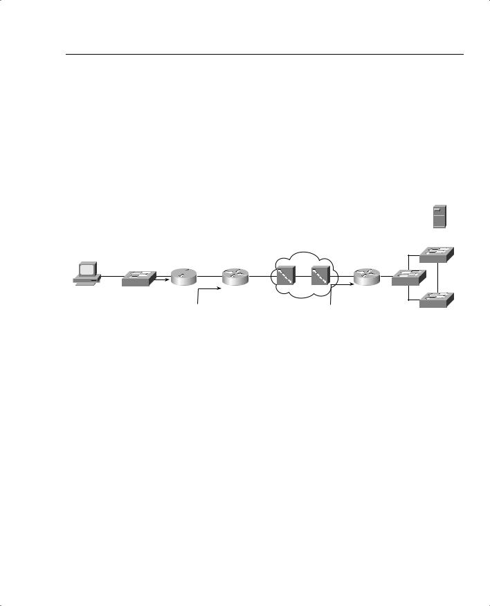
Next, when that same packet leaves R1 over a 56 kbps link to R2, serialization takes 1000 bits/ 56,000 bps, or 17.85 ms. The serialization component over Fast Ethernet is insignificant, whereas serialization becomes a more significant number on lower-speed serial links. Figure 1-6 shows the various locations where the packet from Hannah to Server1 experiences serialization delay.
Figure 1-6 Serialization Delay
IP |
|
|
|
|
|
|
|
Hannah |
|
|
|
|
|
|
|
1 |
2 |
|
|
3 |
|
4 |
5 |
|
SW1 |
R1 |
s0 |
s0 |
R2 |
s1 |
|
|
|
56 |
128 |
|
|||
|
|
|
|
|
|
||
|
|
|
kbps |
|
kbps |
|
Server 1
|
|
|
|
IP |
|
6 |
|
7 |
8 |
|
|
|
||
T1 |
s0 |
R3 |
FA0 |
SW2 |
|
|
|
201
301
As Figure 1-6 shows, serialization delay occurs any time a frame is sent. On LAN links, the delay is insignificant for most applications. At steps 3 through 6 in the figure, the serialization delay is 17.85 ms, 7.8 ms, .02 ms, and .65 ms for the 125-byte packet, respectively. Also note

16 Chapter 1: QoS Overview
that serialization delays do occur inside the Frame Relay cloud. (You can read more about delays inside the cloud in the “Network Delay” section later in this chapter.)
Table 1-4 lists the serialization delay for a couple of frame sizes and link speeds.
Table 1-4 Example Serialization Delay Values
|
Serialization Delay |
Clock Rate |
(125-Byte Frame; |
(1500-Byte Frame; |
of Link |
Milliseconds) |
Milliseconds) |
|
|
|
100 Mbps |
.01 |
.12 |
|
|
|
1.544 Mbps |
.65 |
8 |
|
|
|
512 kbps |
2 |
24 |
|
|
|
128 kbps |
7.8 |
93 |
|
|
|
56 kbps |
17.85 |
214 |
|
|
|
Propagation Delay
Imagine you are watching a train again, this time from a helicopter high in the air over the tracks. You see the train leaving one station, and then arriving at the second station. Using a stopwatch, you measure the amount of time it takes from the first car leaving the first station until the first car arrives at the second station. Of course, all the other cars take the same amount of time to get there as well. This delay is similar to propagation delay in networking.
Propagation delay defines the time it takes a single bit to get from one end of the link to the other. When an electrical or optical signal is placed onto the cable, the energy does not propagate to the other end of the cable instantaneously—some delay occurs. The speed of energy on electrical and optical interfaces approaches the speed of light, and the network engineer cannot override the laws of physics! The only variable that affects the propagation delay is the length of the link. Use the following formula to calculate propagation delay:
Length of Link (meters)
----------------------------------------------------------
3.0 × 10⁸ meters/second
or
Length of Link (meters)
----------------------------------------------------------
2.1 × 10⁸ meters/second
where 3.0 * 108 is the speed of light in a vacuum. Many people use 2.1 * 108 for the speed of light over copper and optical media when a more exact measurement is needed. (Seventy
percent of the speed of light is the generally accepted rule for the speed of energy over electrical cabling.)

QoS: Tuning Bandwidth, Delay, Jitter, and Loss 17
Propagation delay occurs as the bits traverse the physical link. Suppose, for instance, that the point-to-point link between R1 and R2 is 1000 kilometers (1,000,000 meters) long. The propagation delay would be as follows:
1,000,000
----------------------- = 004.8 ms 2.1 × 10⁸
Figure 1-7 shows two contrasting examples of serialization and propagation delay.
Figure 1-7 Serialization and Propagation Delay for Selected Packet and Link Lengths
Server 1
Hannah
1000 km
SW1 |
R1 |
56 kbps |
R2 |
128 kbps |
|
|
Serialization: 125-Byte Packet: 17.86 ms
Serialization: 1250-Byte Packet: 178.6 ms
Propagation: Either Size Packet: 4.8 ms
|
|
|
SW3 |
|
|
10 km |
|
T3 |
T1 |
R3 |
SW2 |
|
|
||
Serialization: 125-Byte Packet: .65 ms |
SW4 |
||
|
|||
Serialization: 1250-Byte Packet: 6.5 ms |
|
||
Propagation: Either Size Packet: .048 ms |
|
As you can see in Figure 1-7, the length of the link affects propagation delay, whereas the size of the packet and link speed affect serialization delay. The serialization delay is larger for larger packets, but the propagation delay is equal for different-sized packets, on the same link. One common misconception is that the link speed, or clock rate, affects propagation delay—it does not! Table 1-5 lists the various propagation delays and serialization delays for parts of Figure 1-6.
Table 1-5 Example Serialization and Propagation Delays with Figure 1-6
Step |
|
|
|
|
|
Number |
|
Clock |
Propagation |
Serialization delay |
Serialization Delay |
from |
Length |
Rate of |
Delay |
(125-Byte Packet; |
(1500-Byte Packet; |
Figure |
of Link |
Link |
(Milliseconds) |
Milliseconds) |
Milliseconds) |
|
|
|
|
|
|
1 |
50 m |
100 |
.002 |
.01 |
.12 |
|
|
Mbps |
|
|
|
|
|
|
|
|
|
2 |
10 m |
100 |
.0004 |
.01 |
.12 |
|
|
Mbps |
|
|
|
|
|
|
|
|
|
3 |
1000 km |
56 kbps |
4.8 |
17.85 |
214 |
|
|
|
|
|
|
continues