


Foundation Summary 303
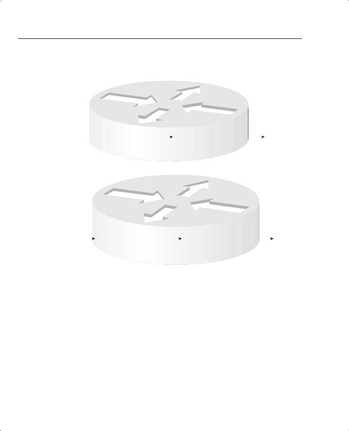
Figure 4-24 Two Output Queues, with Scheduler Always Servicing Queue 1 Rather Than Queue 2 When Packets Are in Queue 1
Assumed Behavior if
No TX Queue
R1 — Serial 0
Output Queue 1 — Preferred Queue
6 Packets: |
|
Packet 6 |
Packet 5 |
Packet 4 |
Packet 3 |
|
|
Scheduler Would Take |
|
First 2 to |
|
|
|
||||||
|
|
|
|
|
|
|
Packets 3-6 from Queue 1 |
||
Queue 2, |
|
|
|
|
|
|
|
|
|
|
|
|
|
|
|
|
|
Before Packets 1-2 from |
|
Next 4 to |
|
|
|
|
|
|
|
||
|
|
|
|
|
|
|
Queue 2 |
||
Queue 1 |
|
|
|
Packet 2 |
Packet 1 |
|
|
||
|
|
|
|
|
|
||||
|
|
|
|
|
|
|
|
|
|
Output Queue 2
Actual Behavior with TX Queue
|
|
|
R1 — Serial0 |
|
|
|
|
|
|
|
|||
6 Packets: |
Output Queue 1 |
|
|
|
|
|
|
|
|||||
First 2 to |
Packet 6 |
Packet 5 |
Packet 4 |
Packet 3 |
|
|
|
TX Queue, Length 2 |
|
||||
|
|
|
|
|
|
||||||||
Queue 2, |
|
|
|
|
|
|
|
|
|
|
Packet 2 |
Packet 1 |
|
|
|
|
|
|
|
|
|
|
|
||||
Next 4 to |
|
|
|
|
|
|
|
|
|
||||
|
|
|
|
|
|
|
|
|
|
|
|||
Queue 1 |
|
|
|
|
|
|
|
Packets Exit in Order |
|
||||
|
|
|
|
|
|
|
|
|
|
|
|||
|
|
|
|
|
|
|
|
|
|
They Arrived |
|
||
|
|
|
|
|
Output Queue 2 |
|
|||||||
The following list summarizes the key points about TX Rings and TX Queues in relation to their effect on queuing:
•The TX Queue/TX Ring always performs FIFO scheduling, and cannot be changed.
•The TX Queue/TX Ring uses a single queue, per interface.
304Chapter 4: Congestion Management
•IOS shortens the interface TX Queue/TX Ring automatically when an output queuing method is configured
•You can configure the TX Ring/TX Queue length to a different value.
To delay the traffic, traffic shaping places the packets into the queue associated with the subinterface or DLCI and drains the traffic from the shaping queue at the shaped rate. Figure 4-25 shows the structure of the queues on a subinterface, interface, and the TX Queue, when shaping is enabled.
Figure 4-25 Shaping Queues, Interface Queues, and TX Ring
Router1
s0/0.1 |
|
|
|
|
|
|
|
|
|
Subinterface |
#1 |
|
|
|
|
|
|
|
|
Shaping Queue |
|
|
|
|
|
|
|
|
|
Interface |
|
|
|
|
|||||
|
|
|
|
|
|
|
|
|
|
|
|
|
|
|
Output Queue |
|
|
TX Ring |
|
|
|
|
|
|
|
|
s0/0 |
||
Subinterface |
#2 |
|
|
|
|
|
|
|
|
Shaping Queue |
|
|
|
|
|
|
|
|
|
|
|
|
|
|
|
|
|
|
|
s0/0.2 |
|
|
|
|
|
|
|
|
|
Table 4-19 summarizes some of the key features of PQ.
Table 4-19 PQ Functions and Features
PQ Feature |
Explanation |
|
|
Classification |
Classifies based on matching an ACL for all Layer 3 protocols, incoming |
|
interface, packet size, whether the packet is a fragment, and TCP and |
|
UDP port numbers. |
|
|
Drop policy |
Tail drop. |
|
|
Maximum number of |
4. |
queues |
|
|
|
Maximum queue length |
Infinite; really means that packets will not be tail dropped, but will be |
|
queued. |
|
|

|
|
Foundation Summary 305 |
|
|
|
Table 4-19 PQ Functions and Features (Continued) |
||
|
|
|
|
PQ Feature |
Explanation |
|
|
|
|
Scheduling inside a single |
FIFO. |
|
queue |
|
|
|
|
|
Scheduling among all |
Always service higher-priority queues first; result is great service for the |
|
queues |
High queue, with potential for 100% of link bandwidth. Service |
|
|
degrades quickly for lower-priority queues. |
|
|
|
Table 4-20 summarizes some of the key features of CQ.
Table 4-20 CQ Functions and Features
CQ Feature |
Explanation |
|
|
Classification |
Classifies based on matching an ACL for all Layer 3 protocols, incoming |
|
interface, packet size, whether the packet is a fragment, and TCP and |
|
UDP port numbers. |
|
|
Drop policy |
Tail drop. |
|
|
Number of queues |
16. |
|
|
Maximum queue length |
Infinite; really means that packets will not be tail dropped, but will be |
|
queued. |
|
|
Scheduling inside a single |
FIFO. |
queue |
|
|
|
Scheduling among all |
Services packets from a queue until a byte count is reached; round- |
queues |
robins through the queues, servicing the different byte counts for each |
|
queue. The effect is to reserve a percentage of link bandwidth for each |
|
queue. |
|
|
Flow-Based WFQ, or simply WFQ, classifies traffic into flows. Flows are identified by at least five items in an IP packet.
•Source IP address
•Destination IP address
•Transport layer protocol (TCP or UDP) as defined by the IP Protocol header field
•TCP or UDP source port
•TCP or UDP destination port
For perspective on the sequence of events for WFQ, marking the sequence number, and serving the queues, examine Figure 4-26.

306 Chapter 4: Congestion Management
Figure 4-26 WFQ—Assigning Sequence Numbers and Servicing Queues
3)Maximum Number of Queues
4)Maximum Queue Length
|
|
|
|
|
|
|
|
|
|
|
|
|
|
|
|
|
|
|
5) Scheduling Inside Queue |
|
6) Scheduler Logic |
|
|
|
||||
|
|
|
|
|
|
|
|
|
|
|
|
|
|
|
|
|
|
|
|
Max 4096 |
|
|
|
Process: Take |
|
|
|
|
|
1) Classification |
Assign SN |
2) Drop Decision |
|
Queues |
|
|
|
|
|
|
|||||||||||||||||
|
|
|
|
|
|
|
|
|
|
|
|
|
|
? |
|
|
|
|
|
|
|
|
|
packet with |
|
|
|
|
|
|
|
|
|
|
|
|
|
|
|
|
|
|
|
|
|
|
|
|
|
|
|
|
|
||||
|
|
|
|
|
|
|
|
|
|
|
SN = Previous_SN |
|
|
|
|
|
|
Max Length |
|
|
|
lowest sequence |
|
|
TX Queue/Ring |
|||
|
|
|
|
|
|
|
|
|
|
|
|
|
|
|
|
|||||||||||||
|
|
|
|
|
|
|
|
|
|
|
+weight*length |
Dropped |
|
|
|
|
|
4096 |
|
|
|
|
number. |
|
|
|
||
|
|
|
|
|
|
|
|
|
|
|
|
|
|
|
|
|
|
|||||||||||
|
|
|
|
|
|
|
|
|
|
|
Weight Based on |
|
|
|
|
|
|
|
|
|
|
|
|
|
Result: Favors |
|
|
|
|
|
|
|
|
|
|
|
|
|
|
|
|
|
|
|
|
|
|
|
|
|
|
|
|
|
|
||
|
|
|
|
|
|
|
|
|
|
|
|
|
|
|
|
|
|
|
. |
|
|
|
|
|
|
|
||
|
|
|
|
|
|
|
|
|
|
|
|
|
|
|
|
|
|
|
|
|
|
|
|
|||||
|
|
|
|
|
|
|
|
|
|
|
IP Precedence |
|
|
|
|
|
|
|
|
. |
|
|
|
|
flows with lower |
|
|
|
|
|
|
|
|
|
|
|
|
|
|
|
|
|
|
|
|
|
|
|
|
|
|
byte volumes and |
|
|
|
||
|
|
|
|
|
|
|
|
|
|
|
|
|
|
|
|
|
|
|
|
|
|
|
|
|||||
|
|
|
|
|
|
|
|
|
|
|
|
Modified Tail |
. |
|
|
|
|
larger precedence |
|
|
|
|||||||
|
|
|
|
|
|
|
|
|
|
|
|
|
|
|
||||||||||||||
Always on Combination Of: |
Drop Based on |
|
|
|
|
|
|
values. |
|
|
|
|||||||||||||||||
Hold Queue and |
|
FIFO |
|
|
|
|
|
|
|
|||||||||||||||||||
- Source/destination IP Address |
|
|
|
|
|
|
|
|
||||||||||||||||||||
CDT |
|
|
|
|
|
|
|
|
||||||||||||||||||||
- Transport Protocol Type |
|
|
|
|
|
|
|
|
|
|
|
|||||||||||||||||
|
|
|
|
|
|
|
|
|
|
|
||||||||||||||||||
|
|
|
|
|
|
|
|
|
|
|
|
|
|
|
|
|
|
|||||||||||
- Source/Destination Port |
|
|
|
|
|
|
|
|
|
|
|
|
|
|
|
|
|
|||||||||||
WFQ calculates the sequence number (SN) before adding a packet to its associated queue. The formula for calculating the SN for a packet is as follows:
Previous_SN + weight * new_packet_ength
Table 4-21 lists the weight values used by WFQ before and after the release of 12.0(5)T/12.1.
Table 4-21 Weight Values Used by WFQ
Precedence |
Before 12.0(5)T/12.1 |
After 12.0(5)T/12.1 |
|
|
|
0 |
4096 |
32384 |
|
|
|
1 |
2048 |
16192 |
|
|
|
2 |
1365 |
10794 |
|
|
|
3 |
1024 |
8096 |
|
|
|
4 |
819 |
6476 |
|
|
|
5 |
682 |
5397 |
|
|
|
6 |
585 |
4626 |
|
|
|
7 |
512 |
4048 |
|
|
|
WFQ discards some packet when a queue’s congestive discard threshold (CDT) has been reached. To appreciate how the CDT is used, examine Figure 4-27.


308 Chapter 4: Congestion Management
Table 4-24 WFQ Functions and Features
WFQ Feature |
Explanation |
|
|
Classification |
Classifies without configuration, based on source/destination IP address/ |
|
port, protocol type (TCP|UDP), and ToS. |
|
|
Drop policy |
Modified tail drop. |
|
|
Number of queues |
4096. |
|
|
Maximum queue length |
Congestive discard threshold per queue (max 4096), with an overall |
|
limit based on the hold queue for all queues (max 4096). |
|
|
Scheduling inside a single |
FIFO. |
queue |
|
|
|
Scheduling among all |
Serves lowest sequence number (SN). The SN is assigned when the |
queues |
packet is placed into the queue, as a function of length and precedence. |
|
|
Table 4-25 summarizes some of the key features of CBWFQ.
Table 4-25 CBWFQ Functions and Features
CBWFQ Feature |
Description |
|
|
Classification |
Classifies based on anything that MQC commands can match, just like |
|
CB marking. Includes all extended IP ACL fields, NBAR, incoming |
|
interface, CoS, precedence, DSCP, source/destination MAC, MPLS |
|
Experimental, QoS group, and RTP port numbers |
|
|
Drop policy |
Tail drop or WRED, configurable per queue. |
|
|
Number of queues |
64. |
|
|
Maximum queue length |
64. |
|
|
Scheduling inside a single |
FIFO on 64 queues; FIFO or WFQ on class-default queue. |
queue |
|
|
|
Scheduling among all |
Algorithm is not published. The result of the scheduler provides a |
queues |
percentage guaranteed bandwidth to each queue. |
|
|
All the commands for CBWFQ are repeated for reference in Tables 4-26 and 4-27.
Table 4-26 Command Reference for CBWFQ
Command |
Mode and Function |
|
|
class-map class-map-name |
Global config; names a class map, |
|
where classification options are |
|
configured. |
|
|
match … |
Class map subcommand; defines |
|
specific classification parameters. |
|
|


310 Chapter 4: Congestion Management
Table 4-26 Command Reference for CBWFQ (Continued)
|
Command |
Mode and Function |
|
|
|
|
random-detect precedence precedence min-threshold max- |
Class subcommand; enables |
|
threshold mark-prob-denominator |
precedence-based WRED in the class. |
|
|
|
|
max-reserved-bandwidth percent |
Interface subcommand; defines the |
|
|
percentage of link bandwidth that can |
|
|
be reserved for CBWFQ queues besides |
|
|
class-default. |
|
|
|
Table 4-27 Exec Command Reference for CBWFQ |
|
|
|
|
|
|
Command |
Function |
|
|
|
|
show policy-map policy-map-name |
Lists configuration information about |
|
|
all MQC-based QoS tools |
|
|
|
|
show policy-map interface-spec [input | output] [class |
Lists statistical information about the |
|
class-name] |
behavior of all MQC-based QoS tools |
|
|
|
To prevent LLQ from having the same problem as PQ, where packets in the highest-priority queue could dominate, LLQ’s scheduler actually works as shown in Figure 4-28.
Figure 4-28 Servicing Queues with LLQ and CBWFQ—The Real Story
|
|
|
|
|
|
|
|
|
|
|
|
|
|
|
|
|
|
|
|
|
|
|
|
|
|
|
|
|
|
|
|
|
|
|
|
|
|
Any |
|
|
|
|
|
Pick Next Packet |
Wait Until TX |
|
|
|||||||||
No |
Ring Has More |
|
|
|
||||||||||||||
Packets in |
|
|
||||||||||||||||
|
|
|
|
|
from Other Non- |
Room |
|
|
|
|||||||||
LLQ? |
|
|
|
|
|
|
|
|||||||||||
|
|
|
|
|
|
|
|
|
|
|
|
|
|
|
||||
|
|
|
|
|
|
|
|
|
|
LLQ Queues |
|
|
|
|
|
|
||
|
Yes |
|
|
|
|
|
|
|
|
|
|
|
|
|
|
|
|
|
|
|
|
|
|
|
|
|
|
|
|
|
|
|
|
|
|
||
|
|
|
|
Discard |
|
|
|
|
|
|
|
|
|
|
||||
|
|
|
|
|
|
|
|
|
|
|
|
|
|
|||||
Packet |
|
Packet |
|
|
|
|
|
|
|
|
|
|
||||||
Yes |
|
|
|
|
|
|
Put Packet in TX |
|
|
|||||||||
|
|
|
|
|
|
|
||||||||||||
Exceeds |
|
|
|
|
|
|
|
|
|
|
Ring |
|
|
|||||
Policed |
|
|
|
|
|
|
|
|
|
|
|
|||||||
|
No |
|
|
|
|
|
|
|
|
|
|
|||||||
Bandwidth? |
|
|
|
|
|
|
|
|
|
|
|
|||||||
|
|
|
|
|
|
|
|
|
|
|
|
|
|
|
||||
|
|
|
|
|
|
|
|
|
|
|
|
|
|
|
||||
|
|
|
|
|
|
|
|
|
|
|
|
|
|
|
|
|
|
|
The single additional configuration command for LLQ is listed in Table 4-28.
Table 4-28 Command Reference for LLQ
Command |
Mode and Function |
|
|
priority{bandwidth-kbps | |
Class subcommand; enables LLQ in this class, reserves bandwidth, and |
percent percentage} |
enables the policing function. The burst for the policer can also be |
[burst] |
configured with this command. |
|
|


312 Chapter 4: Congestion Management
Table 4-31 Summary of Scheduler, Drop, and Number of Queues (Continued)
|
|
|
Max # of |
Tool |
Scheduler |
Drop Policy |
Queues |
|
|
|
|
CQ |
Services packets from a queue until a byte count is |
Tail drop |
16 |
|
reached; round-robins through the queues, servicing |
|
|
|
the different byte counts for each queue. The effect |
|
|
|
is to reserve a percentage of link bandwidth for each |
|
|
|
queue. |
|
|
|
|
|
|
WFQ |
Services lowest sequence number (SN). SNs |
Modified tail |
4096 |
|
assigned when packet placed into queue, as a |
drop* |
|
|
function of length and precedence. |
|
|
|
|
|
|
CBWFQ |
Algorithm is not published. The result of the |
Tail drop or |
64 |
|
scheduler provides a percentage guaranteed |
WRED |
|
|
bandwidth to each queue. |
|
|
|
|
|
|
LLQ |
Always services low-latency queue first, but each |
Tail drop or |
64 |
|
low-latency queue is policed to prevent it from |
WRED |
|
|
dominating the link. |
|
|
|
|
|
|
IP RTP Priority |
Always services low-latency queue first, but queue |
Tail drop |
1 |
|
is policed to prevent it from dominating the link. |
|
|
|
|
|
|
*WFQ’s modified tail drop includes a per-queue limit, an aggregate limit for all queues, with the ability to dequeue a previously enqueued packet if the new packet has a better SN.
Also make sure and review Tables 4-16 and 4-17 immediately preceding the Foundation Summary.