Traffic-Policing and Traffic-Shaping Concepts 323
shaping and policing use similar mechanisms to account for the numbers of bits and bytes sent over time. First, however, we start with the motivations for using shaping and policing.
When and Where to Use Shaping and Policing
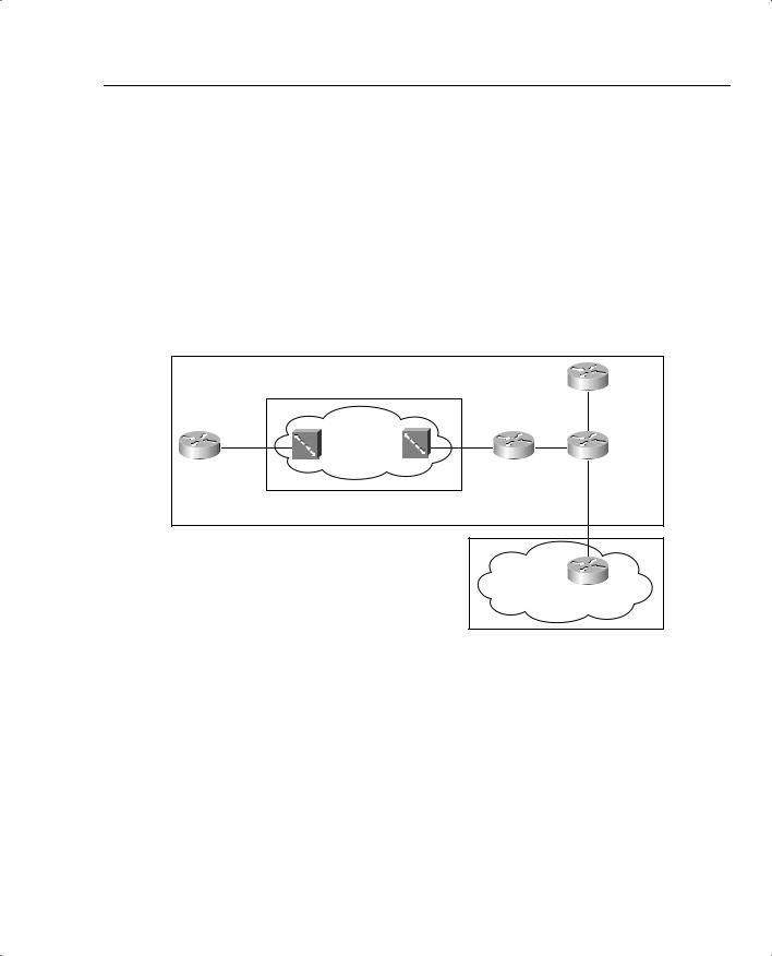
Most implementations of shaping and policing occur at the edges between two different networks. For instance, consider Figure 5-1, which illustrates the two typical cases for shaping and policing. The figure shows PB Tents Enterprise network, with a Frame Relay service, and Internet connectivity using ISP1.
Figure 5-1 Connection to an ISP, and to a Frame Relay Network
PB Tents Enterprise Network
Frame Relay Network |
R4 |
|
|
||
Link1 |
Link2 |
|
AR 128 kbps |
AR 1.544 Mbps |
|
R1 |
R2 |
R3 |
FRS1 |
FRS2 |
|
|
|
Link3 |
|
|
FastE |
|
|
2 Mbps CIR |
|
|
ISP-R1 |
|
ISP |
|
In this case, PB Tents has three separate boundaries between different networks. Link1, between R1 and the Frame Relay network switch labeled FRS1, is the first boundary. The second boundary is between the switch FRS2 and R2. Finally, a boundary exists between R3 and ISP-R1, over Link3.
For each boundary, the legal documents that detail the agreement between PB Tents and the Frame Relay service provider, and the documents that detail the agreement with ISP1, include something called a traffic contract. The need for the contract makes the most sense in the context of Frame Relay, but it also applies to the Internet connection. For instance, R2 uses a T/1 access link into the Frame Relay network. However, the virtual circuit (VC) between R2 and R1 may only include a committed information rate (CIR) of 64 kbps. Similarly, R1 has a 128-kbps access link, and the CIR of the VC to R2 still has a CIR of 64 kbps. When R1 sends
324 Chapter 5: Traffic Policing and Shaping
a packet, the packet is transmitted at 128 kbps—that’s the only speed that physically works! Likewise, R2 must send at 1.5 Mbps. However, the traffic contract may just state that the VC from R1 to R2 allows only 64 kbps in each direction.
Similarly, PB Tents and ISP1 may agree to install a link that is faster than PB Tents actually needs right now, expecting that PB Tent’s Internet traffic loads will grow. When PB Tents needs more capacity to the Internet, each party can just agree to a new traffic contract, and PB Tents will pay ISP1 more money. For instance, metro Ethernet/Fast Ethernet/Gigabit Ethernet services have become more common; most sites do not really need 100 Mbps of bandwidth to the Internet. If PB Tents connected to ISP1 using a Fast Ethernet connection, but the traffic contract stated that PB Tents gets only 2 Mbps of service, however, the same mismatch between physical capability and legal ability, as seen with Frame Relay, occurs on the Internet connection.
In short, policing and shaping can play a role in cases where a router can send more traffic than the traffic contract allows. Shaping just slows the rate of sending packets so that the traffic contract is not exceeded. Policing discards some packets so that the traffic contract is not exceeded.
Policing— When and Where?
Whenever the physical clock rate exceeds the traffic contract, policing may be needed. Suppose, for instance, that ISP1 has 1000 customers, just like PB Tents, each with a 100-Mbps connection, and a contract for support of 2 Mbps. What happens over time? Well, without something to prevent it, each customer will send and receive more and more traffic. For a while, all the customers are happy, because their packets make it through the overbuilt ISP1 core. Even if ISP1 has enough capacity to support 10 Mbps of traffic from every customer, eventually, ISP1’s network will become overrun, because their customers keep sending more and more traffic, so eventually all traffic will suffer. Queues become congested frequently, causing dropped packets. Multimedia traffic suffers through the poor performance as a result of high delay and jitter. TCP sessions continually decrease their window sizes because of the lost packets, causing synchronization effects inside ISP1. ISP1 can add capacity, but that probably means that ISP1 should start charging more to their customers, who may not be willing to upgrade to a higher-traffic contract.
In actual ISP networks, the network engineers design the core of the network expecting some degree of oversubscription. The term “oversubscription” means that the customer has sent and received more traffic than was contracted, or subscribed. As in the example of ISP1 in the preceding paragraph, ISPs and Frame Relay providers build their network expecting some oversubscription. However, they certainly do not build the core expecting every customer to send traffic at full access rate, all the time.
Policing protects a network from being overrun by traffic. If ISP1 just policed traffic from each customer, discarding packets that exceed the traffic contract, it would protect itself from being overrun. However, the decision to add policing to a network can be politically difficult. Suppose that ISP1 has these 1000 customers, each of whom contracted for 2 Mbps of traffic. Each

Traffic-Policing and Traffic-Shaping Concepts 325
customer sends and receives more, averaging 10 Mbps, so that ISP1’s network is becoming too congested. ISP1 chooses to implement policing, using the contracted rate, discarding packets that exceed 2 Mbps of traffic. Of course, most of their customers will be very unhappy! Such a move may be a career-ending, if not business-ending, choice.
Policers can also just mark down the traffic, instead of discarding it. To do so, the policer marks the packet with a different IP precedence or DSCP value when the traffic rate is exceeded, but it still lets the packet through. Later QoS functions, including policers and packet-drop tools such as Weighted Random Early Detection (WRED), can more aggressively discard markeddown packets as compared with those that have not been marked down. Essentially, the policer can increase the chance that a packet will get discarded somewhere else in the network if that packet causes the traffic rate to be exceeded. Generally speaking, when policers mark down packets, if the network is not currently congested, the packet can get through the network; if congested, the packet is much more likely to be discarded.
ISPs make the business choice of whether to police, and how aggressively to police. The options reduce to the following three basic options:
•Do not police. To support the traffic, build the network to support the traffic as if all customers will send and receive data at the clock rate of the access link. From a sales perspective, close deals by claiming that no policing will be done, but encourage customers who exceed their contracts to pay for more bandwidth.
•Police at the contracted rate. To support these traffic levels, the network only needs to be built to support the collective contracted rates, although the core would be overbuilt to support new customers. From a sales perspective, encourage customers that are beginning to exceed their contracts to upgrade, and give incentives.
•Police somewhere in between the contracted rate and the access-link clock rate. For instance, ISP1 might police PB Tents at 5 Mbps, when the contract reads 2 Mbps. The network can be built to support the collective policed rates. The sales team can encourage customers to buy a larger contracted rate when they consistently exceed the contracted rate, but keep customer satisfaction higher by pointing out their generosity by only policing at rates much higher than the contracted rates.
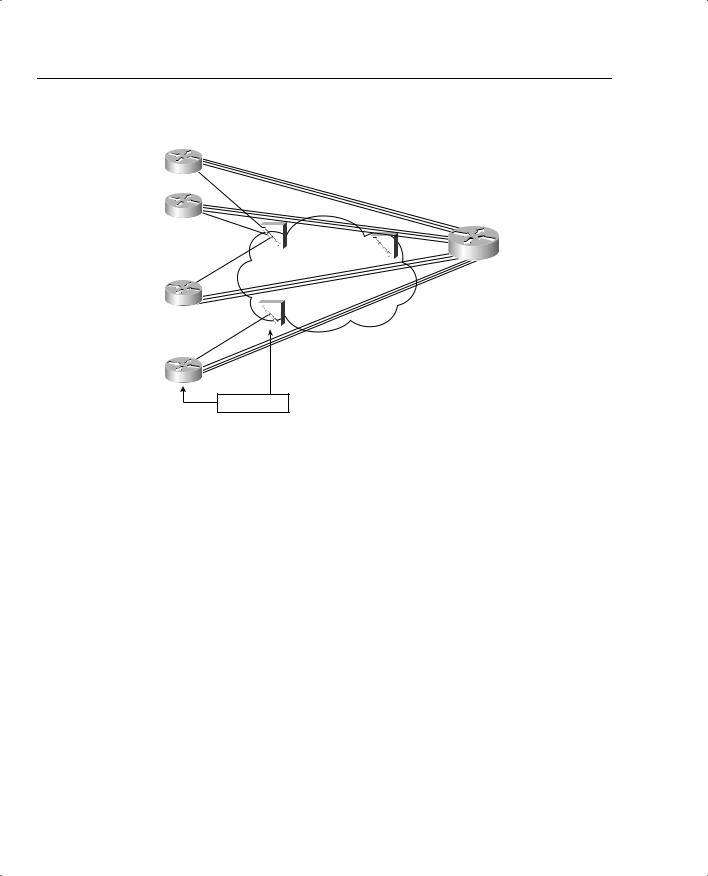
Policing can be useful in multiaccess WANs (Frame Relay and ATM networks) for the same reason that it was useful for the ISP connection described earlier. Whenever data can be sent faster than the contracted rate, the danger exists that a network will be overrun when many sites exceed their contract at the same time. An example will help you understand a few of the issues. Figure 5-2, the network diagram for PB Tents network, has been expanded to show 12 branches, with a single central site.
326 Chapter 5: Traffic Policing and Shaping
Figure 5-2 PB Tents Network, 12 Frame Relay Branches, 1 Central Site
R1 |
|
|
|
|
|
|
|
AR 128 kbps |
|
|
|
|
|||
R2 |
|
|
|
All VCs 64 kbps CIR |
|
|
|
AR 128 kbps |
|
|
|
|
|
|
Main |
|
|
|
|
|
|
||
|
|
|
|
|
|
|
|
AR 128 kbps |
FRS1 |
FRS2 |
|
AR 1.5 Mbps |
|||
|
|
||||||
|
|
||||||
.R3 |
|
|
|
FRS3 |
|
|
|
|
|
|
|
|
|||
. AR 128 kbps |
|
|
|
|
|
|
|
|
|
|
|
|
|
|
|
. |
|
|
|
|
|
|
|
R12
Policing to X kbps
Each branch can send traffic at 128 kbps, but each branch only has a contracted 64-kbps CIR on their respective VCs to the main site. If all 12 sites conform to their CIRs, the Frame Relay network should be able to handle the load. If all 12 sites offer 128 kbps of traffic for long periods, however, the provider may still go ahead and try to forward all the traffic, because most Frame Relay providers overbuild their core networks. They also like to imply in their sales pitch that the customer gets to send excess packets for free.
Of course, at some point, if every customer of this provider sent traffic at full line rates for a period of time, the network would probably congest. The same options exist for the Frame Relay network as for an ISP—not to police but build more capacity; police to CIR, and deal with the sales and customer satisfaction issues; or police at something over CIR, and deal with the sales and customer satisfaction issues in slightly different ways.
To police the network in Figure 5-2, the Frame Relay switches can be configured to perform the policing, or the routers can be used. Traditionally, policing is performed as packets enter a network, which would suggest policing as packets enter the Frame Relay switches from the customer. If the service provider actually controls the edge routers in the enterprise network, however, the policing feature can be performed as packets exit the routers, going toward the Frame Relay cloud. If the customer controls the routers at the edge of the cloud, policing in these routers may be risky for the service provider, just because of the possibility that some customers might turn off policing to get more capacity for free.
The Cisco QoS exams cover policing in IOS routers. The exams do not cover policing in Frame Relay switches, or in LAN switches, although the basic concepts are the same.
Traffic-Policing and Traffic-Shaping Concepts 327
Traffic Shaping— When and Where?
Networks use traffic shaping for two main reasons:
•To shape the traffic at the same rate as policing (if the service provider polices traffic)
•To avoid the effects of egress blocking
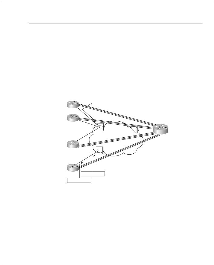
For instance, consider Branches 1 and 24 in Figure 5-3. Branch 1 does not shape, whereas Branch 24 does shape to 96 kbps. In both cases, the Frame Relay switches they are connected to police packets at a 96-kbps rate. (The CIR in each case is 64 kbps. Therefore, the service provider is not policing aggressively. The PB Tents engineer wants to get as much bandwidth as possible out of the service, so he shapes at 96 kbps rather than the 64-kbps CIR.)
Figure 5-3 PB Tents Network, Policing and Shaping, Versus Just Policing
|
|
Policing to 96 kbps |
|
|
|
||||
R1 |
|
|
|
|
|
|
|
|
|
AR 128 kbps |
|
|
|
|
|
||||
|
|
|
|
|
|
||||
R2 |
|
|
|
|
All VCs 64 kbps CIR |
|
|
||
AR 128 kbps |
|
|
|
|
|
|
|
|
Main |
|
|
|
|
|
|
|
|
||
|
|
|
|
|
|
|
|
|
|
AR 128 kbps |
|
|
FRS1 |
|
FRS2 |
|
AR 1.5 Mbps |
||
|
|
|
|
|
|||||
|
|
||||||||
.R3 |
|
|
|
|
FRS3 |
|
|
||
|
|
|
|
|
|
||||
. AR 128 kbps |
|
|
|
|
|
|
|
|
|
|
|
|
|
|
|
|
|
|
|
. |
|
|
|
|
|
|
|
|
|
R24
Policing to 96 kbps
Shaping to 96 kbps
For Branch 1, the absence of shaping ensures that R1 will not artificially delay any packets. However, the policing performed at FRS1 will discard some packets when R1 sends more than 96-kbps worth of traffic. Therefore, some packets will be dropped, although the packets that are not dropped will not experience extra shaping delay. This strategy makes sense when the traffic from Branch 1 is not drop sensitive, but may be delay and jitter sensitive.
For Branch 24, the presence of shaping ensures that R1 will artificially delay some packets. However, the policing performed at FRS3 will not discard packets, because R1 will not send more than 96-kbps worth of traffic. Therefore, no packets will be dropped, although some packets will experience more delay and jitter. This strategy makes sense when the traffic from Branch 24 is drop sensitive, but not delay and jitter sensitive.
328 Chapter 5: Traffic Policing and Shaping
The other reason to use shaping is to avoid the effects of egress blocking. Egress blocking occurs when packets try to exit a multiaccess WAN, such as Frame Relay and ATM, and cannot exit the network because of congestion. Automobile traffic patterns cause the same kinds of behavior as egress blocking. In the morning, for instance, everyone in the state may try to commute to the same small, downtown area of a big city. Even though an eight-lane highway leads into the city, it may seem that everyone living in the surrounding little towns tries to get off at the few exits of the highway between 7 and 8 a.m. each morning. The highway and exits in the downtown area become congested. Similarly, in the afternoon, if everyone tries to reach the suburbs through one exit off the highway at 5:30 p.m., the eight-lane highway feeding into the two-lane exit road becomes congested. Likewise, although plenty of capacity may exist in a network, egress blocking can occur for packets trying to exit the network.
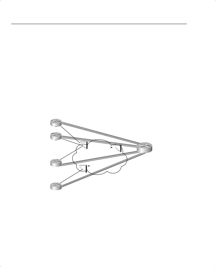
Figure 5-4 illustrates what happens with egress blocking, using a Frame Relay network as an example.
Figure 5-4 PB Tents Network, Egress Blocking
|
|
|
|
|
|
All VCs 64 kbps CIR |
|
|
|
|||||
|
|
|
|
Cumulative Traffic Can Be |
|
|
|
|
||||||
R1 |
|
|
|
24 * 128 kbps = 3.0 Mbps |
|
|
|
|
||||||
AR 128 kbps |
|
|
|
|
|
|
|
|
|
|
||||
R2 |
|
|
|
|
|
|
|
|
|
|
|
|
|
|
AR 128 kbps |
|
|
|
|
|
|
|
|
|
|
|
|
|
Main |
|
|
|
|
|
|
|
|
|
|
|
|
|
||
|
|
|
|
|
|
|
|
|
|
|
|
|
|
|
|
|
|
|
|
|
|
|
|
|
|
|
|
|
|
AR 128 kbps |
|
FRS1 |
|
|
FRS2 |
|
|
AR 1.5 Mbps |
||||||
|
|
|
|
|
|
|
||||||||
|
|
|
|
|||||||||||
.R3 |
|
|
|
|
|
|
|
|
|
|
|
|
|
|
|
|
|
|
FRS3 |
|
|
|
|
|
|
|
|||
. AR 128 kbps |
|
|
|
|
|
|
|
|
|
|
|
|
|
|
|
|
|
|
|
|
|
|
|
|
|
|
|
|
|
. |
|
|
|
|
|
|
|
|
|
|
|
|
|
|
|
|
|
|
|
|
|
|
|
|
|||||
R24 |
Speed Mismatch Between Main (1.5 Mbps) |
|
|
|||||||||||
and R24 Access Rate (128 kbps) Causes Blocking |
|
|
||||||||||||
|
|
|
||||||||||||
|
|
|
|
|
|
|
|
|
|
|
|
|
|
|
Suppose that all 24 branches shape at 64 kbps. The cumulative traffic sent by the branches to the main site is 1.5 Mbps, if each branch simultaneously sends 64 kbps. Because the Main router has a T/1 installed, FRS2 should not experience congestion when forwarding packets out of the access link to the Main router. However, what if shaping were not used at the branches? If all 24 branches were to send traffic at 128 kbps (access rate) for a period of time, the cumulative offered load would be about 3 Mbps. Packets would begin to queue trying to exit FRS2’s interface connected to the Main router. The packets would experience more delay, more jitter,