

56 Chapter 1: QoS Overview
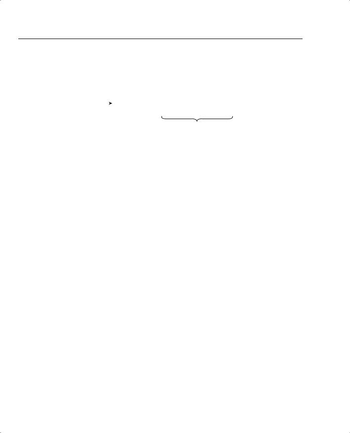
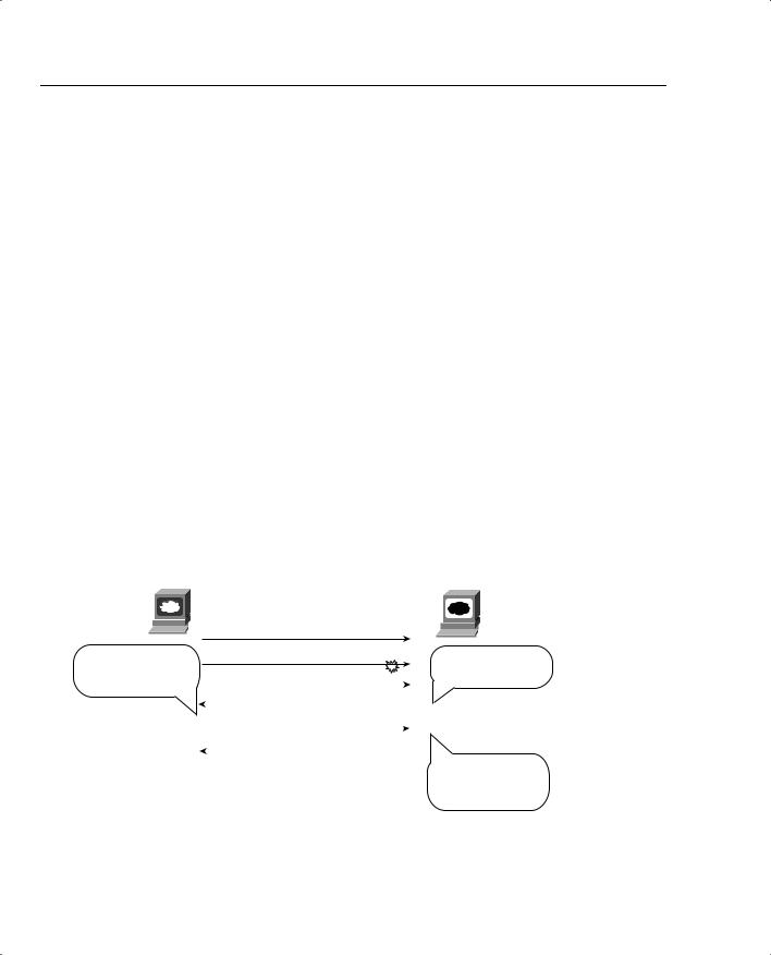
Figure 1-30 Large Playout Buffers for One-Way Video
Receiving Video Device — Delaying Playout Using Large Buffer
Incoming |
|
|
De-Jitter Buffer |
||||||
Video |
|
|
|
|
|
|
|
|
|
Packets |
|
|
............ |
|
|
|
|
|
|
|
|
|
|
|
|
|
|
|
|
|
|
|
|
|
|
|
|
|
|
|
|
|
750 KB — 30 seconds @ 200 kbps |
||||||
|
|
|
|
|
|
|
|
|
|
The initial playout delay takes 30 seconds—not 30 ms, but 30 seconds—in the example of Figure 1-30. No interaction occurs, and no video flows back to the video server; by far, the most important feature is that, when the video does play, it has high quality. With a 30-second dejitter buffer, a cumulative jitter of 30 seconds (not milliseconds) can occur without having playout problems due to delay or jitter.
For two-way interactive packet video, delay of course does impact quality. The previous section about voice and voice delay explains most of what you need to know about video delay. Video experiences codec delay, packetization delay, and de-jitter (initial playout) delay. Of particular note, video delay budgets typically run from 0 to 200 ms for high-quality video conferencing, and de-jitter initial playout delays typically range from 20 to 70 ms.
Video Jitter Considerations
Just like for delay, one-way video tolerates jitter much more so than two-way, interactive video. When planning for QoS, two-way video should be treated just like voice in terms of minimizing delay. Furthermore, proper and accurate bandwidth allocation/provisioning is recommended. One-way, streaming video should be given enough bandwidth, but extra delay and jitter can be tolerated.
Jitter concerns for video networks can be summarized as follows:
•Jitter still happens in packet networks.
•De-jitter buffers on the receiving side compensate for some jitter.
•De-jitter buffers for interactive video typically run in the tens of milliseconds, allowing even small amounts of jitter to affect video quality.
•De-jitter buffers for streaming video typically run into the tens of seconds, allowing significant jitter to occur without affecting video quality
•QoS tools, particularly queuing and fragmentation tools, can reduce jitter to low enough values such that the de-jitter buffer for interactive video works effectively.
Traffic Characteristics of Voice, Video, and Data 57
Video Loss Considerations
Video flows degrade when packets are lost. The picture becomes jerky due to missing frames, the images freeze, and the audio may cut in and out. In short, video does not tolerate loss very well.
Routers drop packets for many reasons; packet loss due to full queues can be addresses with several types of QoS tools. Remember, tail drop describes the situation when a queue fills, another packet needs to be added to the queue, so the router throws away the packet that needs to be added to the tail of the queue. You can use four general QoS strategies to reduce the chance of lost (dropped) video packets:
•Enable queuing and putting video in a different queue than bursty data traffic.
•Configure the video queue to be longer.
•Enable CAC to protect the video queue from having too many concurrent video flows in it—in other words, CAC can protect video from other video streams.
•Use a Random Early Detect (RED) tool on the loss-tolerant flows (typically data, not video!), which causes those flows to slow down, which in turn reduces overall interface congestion.
Comparing Voice and Video: Summary
Table 1-24 summarizes the QoS requirements of video in comparison to voice.
Table 1-24 Comparing Voice and Video QoS Requirements
|
|
Bandwidth |
|
Delay |
|
Jitter |
Loss |
|||||
|
|
|
|
|
|
|
|
|
|
|
|
|
Voice Payload |
|
|
|
Low |
|
Low |
Low |
|||||
|
Low |
|
|
|
||||||||
|
|
|
|
|
|
|
|
|
|
|
|
|
Video Payload— |
|
|
|
|
|
Low |
|
Low |
Low |
|||
|
High |
|
|
|
||||||||
Interactive |
|
|
|
|
|
|
|
|
|
|
|
|
(2-Way) |
|
|
|
|
|
|
|
|
|
|
|
|
|
|
|
|
|
|
|
|
|
|
|
|
|
Video Payload— |
|
|
|
|
|
|
|
|
|
Low |
||
|
High |
|
|
High |
|
|
High |
|
||||
Streaming |
|
|
|
|
|
|
|
|
|
|
|
|
(1-Way) |
|
|
|
|
|
|
|
|
|
|
|
|
|
|
|
|
|
|
|
|
|
|
|
|
|
Video Signaling |
|
Low |
|
Low |
|
Medium |
Medium |
|||||
|
|
|
|
|
|
|
|
|
|
|
|
|
Voice Signaling |
|
Low |
|
Low |
|
Medium |
Medium |
|||||
|
|
|
|
|
|
|
|
|
|
|
|
|
Data Traffic Characteristics
This book, as well as the exams about which this book prepares you, assumes you have a fairly high level of knowledge about data traffic before using this book. In fact, the QoS and DQOS courses assume that you have been to the ICND and BSCI courses at least, and hopefully the
58 Chapter 1: QoS Overview
BCMSN and CVOICE courses. In fact, when DQOS first came out, the expectation was that students should be CCNPs before attending the course.
QoS has always been important, but QoS has become vitally important with the convergence of data, voice, and video into a single network. As with any convergence of technologies, professionals working in the networking arena come from many different backgrounds. This section about data is intended for those who do not come from a data background.
NOTE If you want to read more on TCP/IP protocols, take a look at the latest Douglas Comer’s Internetworking with TCP/IP books. Volume 1 is most appropriate for networking engineers. A good alternative is Richard Stevens’s TCP/IP Illustrated, Volume I.
Just like the coverage of voice and video in this chapter, this section breaks down an analysis of data traffic as it relates to the four QoS characteristics: bandwidth, delay, jitter, and loss. The discussion begins with the basics of data application flows, followed by QoS details as they relate to data in terms of the four QoS characteristics.
IP Data Basics
With voice and video, signaling occurred first in order to create the voice or video call. Although it is not called signaling in the data world, something similar does occur—for instance, when you open a web browser, and browse www.cisco.com, several things happen before the first parts of the web page appear. For our purposes for QoS, this book focuses on the actual payload flows—the actual data—rather than the data equivalent of signaling.
Most applications use one of two TCP/IP transport layer protocols: User Datagram Protocol (UDP) or Transmission Control Protocol (TCP). The person writing the application chooses which transport layer protocol to use. Most of the time the application programmer uses standard protocols, which tell them whether to use TCP or UDP. For instance, web servers use TCP, so if writing a web application, TCP is used.
TCP performs error recovery, but UDP does not. To perform error recovery, TCP sends some initialization messages to create a TCP connection, which coincidentally initializes some counters used to perform the error recovery. Figure 1-31 shows an example of connection establishment.
TCP signals connection establishment using 2 bits inside flags field of the TCP header. Called the SYN and ACK flags, these bits have a particularly interesting meaning. SYN means “synchronize the sequence numbers,” which is one necessary component in initialization for TCP. The ACK field means “the acknowledgment field is valid in this header.”
Traffic Characteristics of Voice, Video, and Data 59
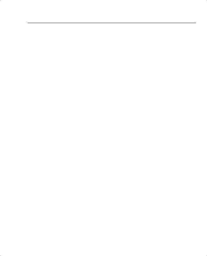
Figure 1-31 TCP Connection Establishment
SEQ = 999
SYN, DPORT=80, SPORT=1027
SEQ=1450, ACK=1000
SYN, ACK, DPORT=1027, SPORT=80
Web |
SEQ=1000, ACK=1451 |
Web |
Browser |
ACK, DPORT=80, SPORT=1027 |
Server |
|
|
|
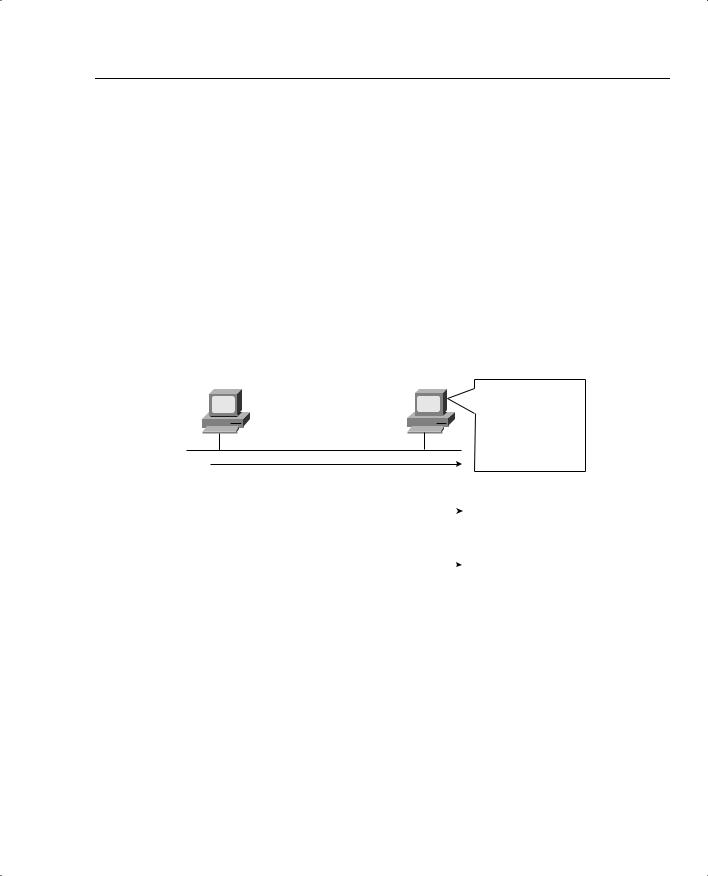
When the three-way TCP handshake is complete, the TCP connection is up, and error recovery can be performed. Figure 1-32 shows how the sequence and acknowledgment fields are used, after the connection has been established.
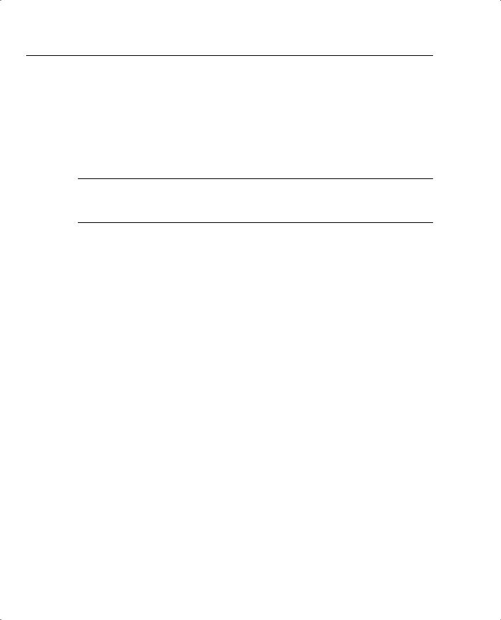
Figure 1-32 TCP Acknowledgments
Web server
ACK=1000
Window=3000
SEQ=1000
SEQ=2000
SEQ=3000
ACK=4000  Window=4000 SEQ=4000 SEQ=5000 SEQ=6000 SEQ=7000
Web browser
In the figure, the server sends data and labels it with the sequence number. The acknowledgment field in the TCP header sent back to the server by the web client (4,000) implies the next byte to be received; this is called forward acknowledgment. In essence, the browser acknowledged the receipt of all three packets, with sequence numbers 1000, 2000, and 3000. (Each packet contains 1000 bytes of data in this example.) The sequence number reflects the number of the
60 Chapter 1: QoS Overview
first byte in the segment. Keep in mind that on the packet whose sequence number is 3000, with 1000 bytes, that bytes 3000 to 3999 are in the packet—so the browser should expect to get byte 4000 next.
TCP also controls the rate of sending data using windowing. This window field implies the maximum number of unacknowledged bytes allowed outstanding at any instant in time. Figure 1-34 shows windowing with a current window size of 3000, which increases to a window of 4000 by the end of the example. (Remember, each TCP segment has 1000 bytes of data in this example.) The window then “slides” up and down based on network performance, so it is sometimes called a sliding window. When the sender sends enough bytes to consume the current window, the sender must wait for an acknowledgment, which controls the flow of data. Effectively, the available window decreases as bytes are sent and increases as acknowledgment for those bytes are received.
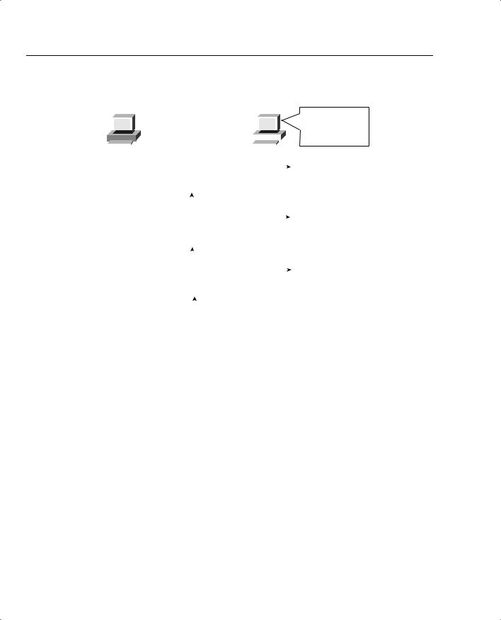
The biggest difference between TCP and UDP is that TCP performs error recovery. Therefore, some people refer to TCP as reliable, and UDP as unreliable. And remember, voice and video flows that use RTP also use UDP—so why would voice and video use a protocol that is unreliable? The answer is simple: By the time a voice or video packet was sent, and TCP noticed that the packet was lost, and caused a retransmission, far too much delay would have already occurred. Therefore, resending the voice or video packet would be pointless. For data applications, however, where all the data really does need to make it to the other side of the connection, even if it takes additional time, TCP can be very useful. Figure 1-33 outlines the basic error-recovery logic of TCP.
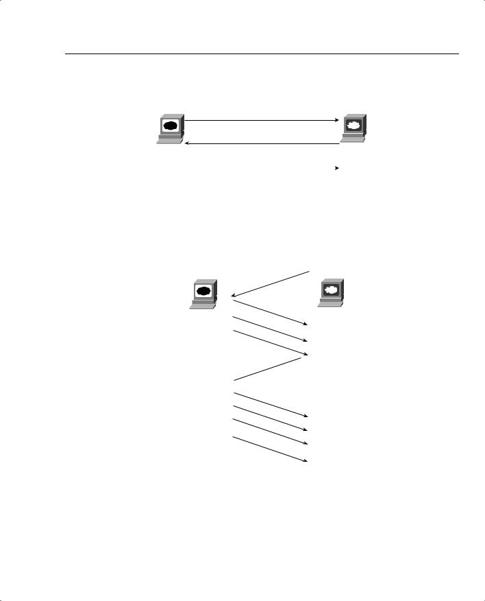
Figure 1-33 TCP Error Recovery
Web server
1000 bytes of data, Sequence = 1000
He lost the segment 1000 bytes of data, Sequence = 2000 with Sequence =
2000. Resend it! |
1000 bytes of data, Sequence = 3000 |
|
||
|
No data, Acknowledgment = 2000 |
|
||
|
|
|
|
|
|
|
1000 bytes of data, Sequence = 2000 |
|
|
|
|
|
|
|
|
|
|
No data, Acknowledgment = 4000 |
|
Web browser
I probably lost one. ACK what I got in order!
I just got 2000-2999, and I already had 3000-3999. Ask for 4000 next.
Traffic Characteristics of Voice, Video, and Data 61
Figure 1-33 depicts a flow where the second TCP segment was lost or was in error. The web client’s reply has an ACK field equal to 2000, implying that the web client is expecting byte number 2000 next. The TCP function at the web server then could recover lost data by resending the second TCP segment. The TCP protocol allows for resending just that segment and then waiting, hoping that the web client will reply with an acknowledgment that equals 4000.
Finally, you should understand one additional feature of TCP and UDP before continuing with your examination of QoS. That feature concerns a part of the TCP and UDP headers called the source and destination port numbers. The main purpose for port numbers can be seen with a simple example; for QoS, port numbers can be used to classify a packet, which in turn allows a router or switch to choose a different QoS action. In this case, Hannah is using three applications, and server Jessie is the server for all three applications. This particular company wrote an Advertising application and a wire-transfer application, both in use. In addition, Hannah is using a web-based application, as shown in Figure 1-34.
Figure 1-34 Hannah Sending Packets to Jessie, with Three Applications
Hannah |
Jessie |
Web server
Ad application
Wire application
|
Eth |
IP |
UDP |
Ad Data |
Eth |
|
|
|
|
|
|
|
|
|
|
|
|
|
|
|
I received three packets, each from the same MAC and IP address. What application should get the data in each packet?
|
Eth |
IP |
TCP |
Wire |
Eth |
|
|
transfer data |
|
||||
|
|
|
|
|
|
|
|
|
|
|
|
|
|
|
|
|
|
|
|
|
|
Eth |
IP |
TCP |
Web page |
Eth |
|
|
data |
|
||||
|
|
|
|
|
|
After receiving a packet, Jessie needs to know which application to give the data to, but all three packets are from the same Ethernet and IP address. You might think that Jessie could look at whether the packet contains a UDP or a TCP header, but, as you see in the figure, two applications (wire transfer and web) both are using TCP. Well, UDP and TCP designers purposefully included a port number field in the TCP and UDP headers to allow multiplexing. “Multiplexing” is the term generally used to describe the capability to determine which application gets the data for each packet. Each of the applications uses a different port number, so Jessie knows which application to give the data to, as seen in Figure 1-35.
62 Chapter 1: QoS Overview
Figure 1-35 Hannah Sending Packets to Jessie, with Three Applications Using Port Numbers to Multiplex
|
Hannah |
|
|
|
|
|
|
|
|
|
Jessie |
I’ll look in the UDP |
||||||||||||||
|
|
|
|
|
|
|
|
|
|
Port 80 Web server |
|
|
|
|
|
|
|
|
|
|||||||
|
|
|
|
|
|
|
|
|
|
|
|
|
|
|
|
|
|
|
or TCP destination |
|||||||
|
|
|
|
|
|
|
|
|
|
Port 800 Ad server |
|
|
|
|
|
|
|
|
|
|||||||
|
|
|
|
|
|
|
|
|
|
|
|
|
|
|
|
|
|
|
port to identify the |
|||||||
|
|
|
|
|
|
|
|
Port 20,100 Wire application |
|
|
|
|
|
|
|
|
|
|
|
|||||||
|
|
|
|
|
|
|
|
|
|
|
|
|
|
|
|
|
|
|
application! |
|||||||
|
|
|
|
|
|
|
|
|
|
|
|
|
|
|
|
|
|
|
|
|
|
|
|
|
|
|
|
|
|
|
|
|
|
|
|
|
|
|
|
|
|
|
|
|
|
|
|
|
|
|
|
|
|
|
|
|
|
|
|
|
|
|
|
|
|
|
|
|
|
|
|
|
|
|||||||
|
|
|
|
|
|
|
|
|
|
|
|
|
|
|
|
|
|
|
|
|||||||
|
|
|
Eth |
IP |
UDP |
Ad Data |
|
|
Eth |
|
|
|
|
|
||||||||||||
|
|
|
|
|
|
|
|
|
|
|
|
|
|
|
|
|
|
|
|
|
|
|||||
|
|
|
|
|
|
|
|
|
|
|
|
|
|
Destination port 800 |
|
|||||||||||
|
|
|
|
|
|
|
|
|
|
|
|
|
|
|
||||||||||||
|
|
|
|
|
|
|
|
|
|
|
|
|
|
|
||||||||||||
|
|
|
|
|
|
|
|
|
|
|
|
|
|
|
|
|
|
|
|
|
|
|
|
|
||
|
|
|
|
|
|
|
|
|
|
|
|
|
|
|
|
|
|
|
|
|
|
|
|
|
|
|
|
|
|
Eth |
|
IP |
|
TCP |
|
Wire |
Eth |
|
|
|
|
|
|||||||||||
|
|
|
|
|
|
transfer data |
|
|
|
|
|
|||||||||||||||
|
|
|
|
|
|
|
|
|
|
|
|
|
|
|
|
|
|
|
|
|
|
|
|
|||
|
|
|
|
|
|
|
|
|
|
|
|
|
|
Destination port 20,100 |
|
|||||||||||
|
|
|
|
|
|
|
|
|
|
|
|
|
|
|
||||||||||||
|
|
|
|
|
|
|
|
|
|
|
|
|
|
|
||||||||||||
|
|
|
|
|
|
|
|
|
|
|
|
|
|
|
|
|
|
|
|
|
|
|
|
|
||
|
|
|
|
|
|
|
|
|
|
|
|
|
|
|
|
|
|
|
|
|
|
|
|
|
|
|
|
|
|
Eth |
IP |
TCP |
Web page |
|
Eth |
|
|
|
|
||||||||||||||
|
|
|
data |
|
|
|
|
|||||||||||||||||||
|
|
|
|
|
|
|
|
|
|
|
|
|
|
|
|
|
|
|
|
|
|
|
|
|||
|
|
|
|
|
|
|
|
|
|
|
|
|
|
Destination port 80 |
|
|||||||||||
|
|
|
|
|
|
|
|
|
|
|
|
|
|
|
||||||||||||
|
|
|
|
|
|
|
|
|
|
|
|
|
|
|
||||||||||||
Most well-known applications, such as web, FTP, TFTP, Telnet, SMTP, POP3, and so on, use a well-known port. Using an application would be cumbersome if before you used it you had to call someone to find out what port number it uses. With well-known ports, you can assume that web servers use port 80, for instance. For QoS tools, if you want to classify web traffic, you can just look for packets that use port 80.
Certainly, you could spend a career just learning about, and working with, all the protocols inside the realm of TCP/IP. This brief introduction provides a little background that will help with some of the things you will read about in later sections. Table 1-25 lists the key points to remember about TCP and UDP.
Table 1-25 TCP and UDP Comparison Chart
Feature |
TCP |
UDP |
|
|
|
Error recovery |
Yes |
No |
|
|
|
Uses port number |
Yes |
Yes |
|
|
|
Uses windowing for |
Yes |
No |
flow control |
|
|
|
|
|
The next few sections of this book examine data more closely in relation to the four QoS characteristics: bandwidth, delay, jitter, and loss.