

626 Chapter 8: Call Admission Control and QoS Signaling
Foundation Summary
The “Foundation Summary” is a collection of tables and figures that provide a convenient review of many key concepts in this chapter. For those of you already comfortable with the topics in this chapter, this summary could help you recall a few details. For those of you who just read this chapter, this review should help solidify some key facts. For any of you doing your final prep before the exam, these tables and figures are a convenient way to review the day before the exam.
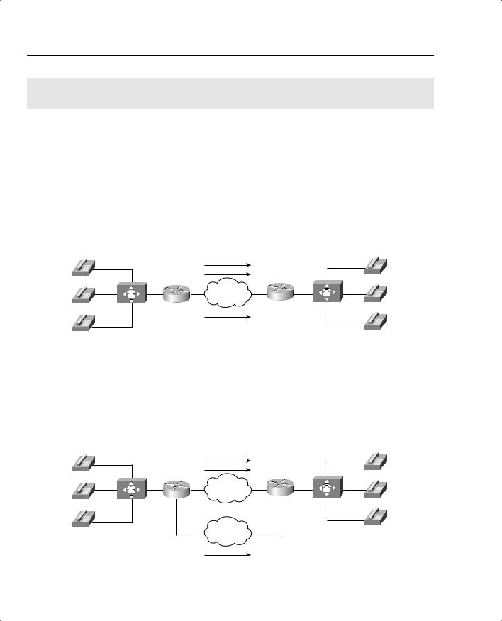
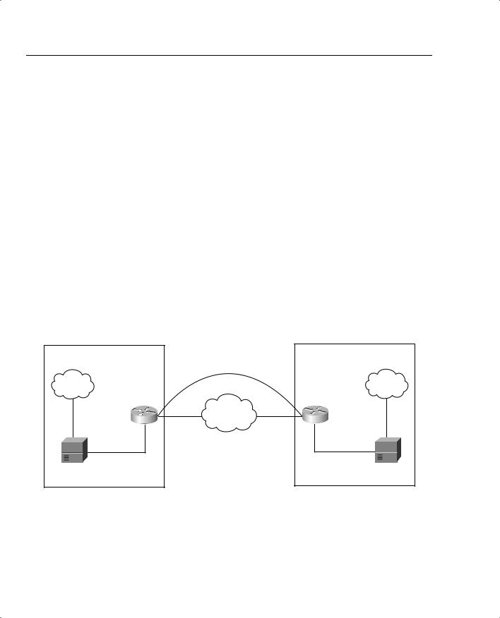
Figure 8-35 shows the effect of a VoIP network without the use of CAC.
Figure 8-35 VoIP Network Without CAC
IP Network Supports 2 Calls Max!
|
Call 1 |
|
|
Call 2 |
|
R1 |
IP Network |
R2 |
|
Call 3
The Third Call Degrades Voice Quality for All Calls
Figure 8-36 shows how CAC can be used in a legacy VoIP network to redirect a call to the PSTN in the even that sufficient resources are not available to carry the call on the data network.
Figure 8-36 Legacy VoIP Network with CAC
IP Network Supports 2 Calls Max!
|
Call 1 |
|
|
Call 2 |
|
R1 |
IP Network |
R2 |
|
PSTN
Call 3
CAC Reroutes the Third Call Through the PSTN

Foundation Summary 627
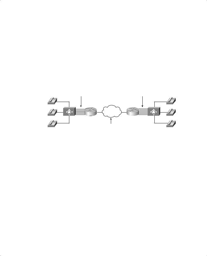
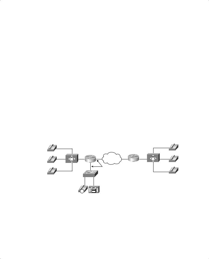
Figure 8-37 shows how CAC can be used in an IP telephony network to redirect a call to the PSTN in the event that sufficient resources are not available to carry the call on the data network.
Figure 8-37 IP Telephony Network with CAC
|
IP Network Supports 2 Calls Max! |
|
|
|
Host Site |
Call 1 |
Remote Site |
||
|
|
Call 2 |
|
|
IP |
R1 |
IP Network |
R2 |
IP |
|
||||
Host Phone A |
|
|
|
Remote |
|
|
|
|
Phone A |
IP |
SW1 |
PSTN |
SW2 |
IP |
Host Phone B |
|
|
||
|
|
|
|
Remote |
|
|
Call 3 |
|
Phone B |
|
|
|
|
|
IP |
|
CAC Reroutes the Third Call |
|
|
Host Phone C |
|
|
IP |
|
|
|
Through the PSTN |
|
|
|
|
|
Remote |
|
|
|
|
|
|
|
|
|
|
Phone C |
CallManager |
CallManager |
|
|
|
Publisher |
Subscriber |
|
|
|
Table 8-26 illustrates a few of the possible G.711 and G.729 bandwidth requirements.
Table 8-26 Bandwidth Requirements
|
Payload |
|
|
|
Packets |
|
|
per |
IP/UDP/RTP |
L2 Header |
L2 Header |
per |
Bandwidth |
Codec |
Packet |
Header Size |
Type |
Size |
Second |
per Call |
|
|
|
|
|
|
|
G.711 |
160 bytes |
40 bytes |
Ethernet |
14 bytes |
50 pps |
85.6 kbps |
|
|
|
|
|
|
|
G.711 |
240 bytes |
40 bytes |
Ethernet |
14 bytes |
33 pps |
77.6 kbps |
|
|
|
|
|
|
|
G.711 |
160 bytes |
40 bytes |
MLPPP/FR |
6 bytes |
50 pps |
82.4 kbps |
|
|
|
|
|
|
|
G.711 |
160 bytes |
2 bytes (cRTP) |
MLPPP/FR |
6 bytes |
50 pps |
67.2 kbps |
|
|
|
|
|
|
|
G.729 |
20 bytes |
40 bytes |
Ethernet |
14 bytes |
50 pps |
29.6 kbps |
|
|
|
|
|
|
|
G.729 |
20 bytes |
40 bytes |
MLPPP/FR |
6 bytes |
50 pps |
26.4 kbps |
|
|
|
|
|
|
|
G.729 |
30 bytes |
40 bytes |
MLPPP/FR |
6 bytes |
33 pps |
20 kbps |
|
|
|
|
|
|
|
G.729 |
20 bytes |
2 bytes (cRTP) |
MLPPP/FR |
6 bytes |
50 pps |
11.2 kbps |
|
|
|
|
|
|
|
*For DQOS test takers: These numbers are extracted from the DQOS course, so you can study those numbers. Note, however, that the numbers in the table and following examples do not include the L2 trailer overhead.

628 Chapter 8: Call Admission Control and QoS Signaling
Figure 8-38 illustrates the packet structure of the layer 2 and IP/UDP/RTP headers and the payload for a voice packet.
Figure 8-38 Voice Packet Structure
Layer 2 |
IP |
UDP |
RTP |
Payload of Speech Samples |
Variable |
|
|
|
Variable Size Based on Codec |
Size |
20 |
8 |
12 |
Selection and Number of |
Based on |
Bytes |
Bytes |
Bytes |
Speech Samples Included |
Layer 2 |
|
|
|
|
Protocol |
|
|
|
|
|
|
|
|
|
Table 8-27 describes the criteria that is used to evaluate the different CAC tools.
Table 8-27 CAC Feature Evaluation Criteria
Evaluation Criteria |
Description |
|
|
Voice over X (VoX) |
The voice technologies to which the CAC method applies, such as VoIP |
supported |
and VoFR. Some methods apply to a single technology, whereas other |
|
methods apply to multiple technologies. |
|
|
Toll bypass or IP telephony |
Whether the method is suitable for use only between voice gateways |
|
connected to the PSTN or a PBX (toll bypass), or will the method |
|
function with IP Phone endpoints (IP telephony). |
|
|
Platforms and releases |
The Cisco IOS platforms this feature is available on, and the software |
|
release in which it was introduced. |
|
|
PBX trunk types supported |
Some CAC features have a dependency on the PSTN or PBX trunk type |
|
used in the connection, or act differently with CCS trunks versus CAS |
|
trunks. |
|
|
End-to-end, local, or IP |
The scope of visibility of the CAC feature. Some mechanisms work |
cloud |
locally on the originating gateway only, others consider the cloud |
|
between the source and destination nodes, some consider the destination |
|
POTS interface, and some work end to end. |
|
|
Per call, interface, or |
Different mechanisms involve different elements of the network. Several |
endpoint |
CAC methods work per call, but some work per interface and some work |
|
per endpoint or IP destination. |
|
|
Topology awareness |
Whether the CAC mechanism takes into account the topology of the |
|
network, and therefore provides protection for the links and nodes in the |
|
topology. |
|
|
Guarantees QoS for |
Whether the mechanism make a one-time decision before allowing the |
duration of call |
call, or whether it also protects the QoS of the call for the duration of the |
|
call by reserving the required resources. |
|
|
|
|
Foundation Summary 629 |
|
|
|
Table 8-27 CAC Feature Evaluation Criteria (Continued) |
||
|
|
|
|
Evaluation Criteria |
Description |
|
|
|
|
Postdial delay |
Whether the mechanism imposes an additional postdial delay because it |
|
|
requires extra messaging or processing during call setup. |
|
|
|
|
Messaging network |
Whether the method uses additional messaging that must be provisioned |
|
overhead |
in the network to gather the information necessary for the CAC decision. |
|
|
|
Figure 8-39 illustrates a network using physical DS0 limitation to provide CAC.
Figure 8-39 VoIP Physical DS0 Limitation
Six Physical Connections Between Each PBX and Router
R1 |
IP Network |
R2 |
IP Network Designed to Handle up to Six G.729 Calls
Table 8-28 evaluates the physical DS0 limitation mechanism against the CAC evaluation criteria described earlier in this chapter.
Table 8-28 DS0 Limitation CAC Evaluation Criteria
Evaluation Criteria |
Value |
|
|
VoX supported |
Independent of the VoX technology used |
|
|
Toll bypass or IP Telephony |
Toll bypass only |
|
|
Platforms and releases |
All voice gateways and all Cisco IOS releases |
|
|
PBX trunk types supported |
All |
|
|
End to end, local, or IP cloud |
Local |
|
|
Per call, interface, or endpoint |
Per DS0/trunk (per call) |
|
|
Topology awareness |
None |
|
|
Guarantees QoS for duration of call |
None |
|
|
Postdial delay |
None |
|
|
Messaging network overhead |
None |
|
|
|
|
Foundation Summary 631 |
|
|
|
Table 8-29 Max-Connections CAC Evaluation Criteria |
||
|
|
|
|
Evaluation Criteria |
Value |
|
|
|
|
VoX supported |
All VoX that use dial peers |
|
|
|
|
Toll bypass or IP telephony |
Toll bypass only |
|
|
|
|
Platforms and releases |
All voice gateways and all Cisco IOS releases |
|
|
|
|
PBX trunk types supported |
All |
|
|
|
|
End to end, local, or IP cloud |
Local |
|
|
|
|
Per call, interface, or endpoint |
Per dial peer |
|
|
|
|
Topology awareness |
None |
|
|
|
|
Guarantees QoS for duration of call |
None |
|
|
|
|
Postdial delay |
None |
|
|
|
|
Messaging network overhead |
None |
|
|
|
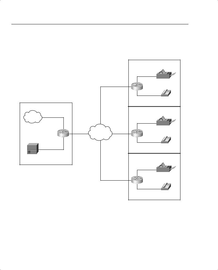
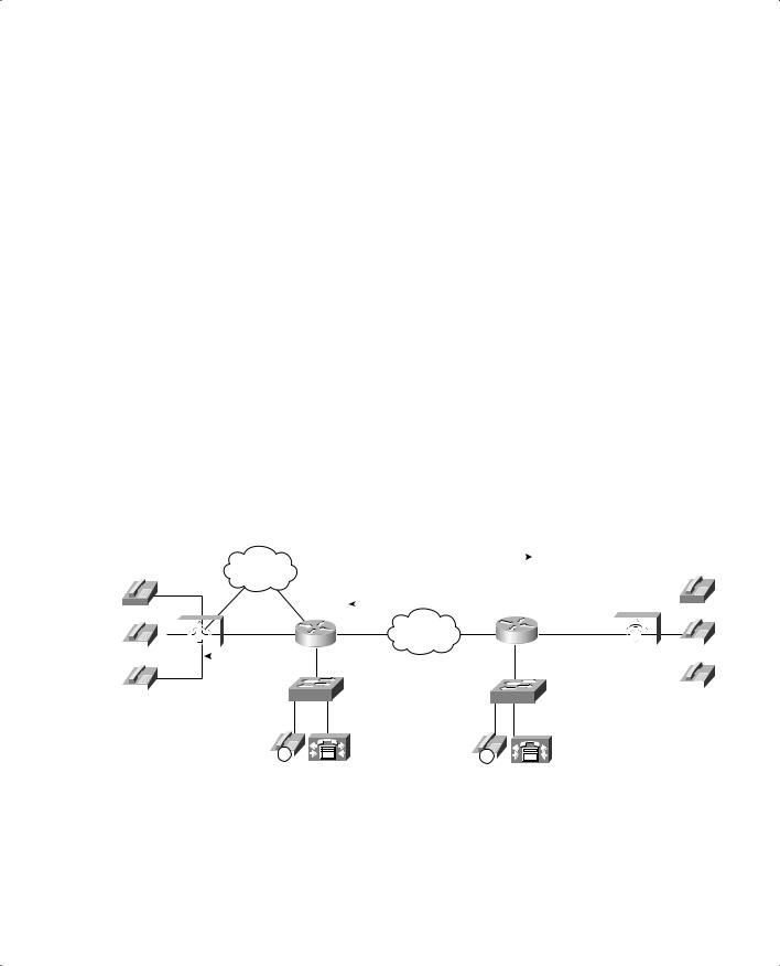
Figure 8-41 shows a typical VoFR network that can use the frame-relay voice-bandwidth command to limit the number of calls between locations.
Figure 8-41 Voice over Frame Relay (VoFR)
Host Site |
|
|
|
Remote Site |
|
|
256 kbps |
|
256 kbps |
4 Fax Machines |
|
|
Frame |
Extensions 12xx |
|||
T1 PRI |
Circuit |
Circuit |
|||
Relay |
|
||||
|
|
|
|
||
PBX |
|
|
|
|
|
Extensions 5xxx |
|
|
|
|
|
|
|
|
|
10 Telephones |
|
|
|
|
|
Extensions 12xx |
Table 8-30 evaluates the VoFR Voice-Bandwidth mechanism against the CAC evaluation criteria described earlier in this chapter.
632 Chapter 8: Call Admission Control and QoS Signaling
Table 8-30 VoFR Voice-Bandwidth CAC Evaluation Criteria
Evaluation Criteria |
Value |
|
|
VoX supported |
VoFR |
|
|
Toll bypass or IP telephony |
Toll bypass only |
|
|
Platforms and releases |
Cisco 2600s, 3600s, 3810, and 7200 router; Cisco IOS |
|
Release 12.0(4)T |
|
|
PBX trunk types supported |
All |
|
|
End to end, local, or IP cloud |
Local |
|
|
Per call, interface, or endpoint |
Per call, per PVC |
|
|
Topology awareness |
None |
|
|
Guarantees QoS for duration of call |
None |
|
|
Postdial delay |
None |
|
|
Messaging network overhead |
None |
|
|
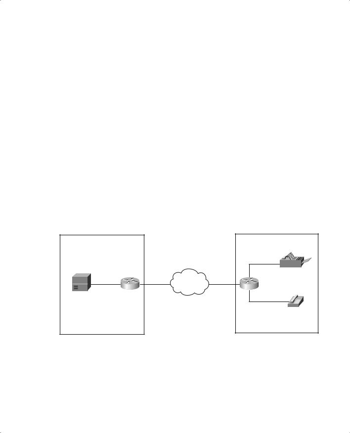
Figure 8-42 shows a VoIP network using the connection trunk command to emulate a circuit switched network.
Figure 8-42 Trunk Conditioning
Host Site |
Connection |
Remote Site |
|
|
|
|
Trunk |
|
PSTN |
|
PSTN |
256 kbps |
|
256 kbps |
Circuit |
Frame Relay |
Circuit |
|
|
|
T1 PRI |
|
|
PBX |
|
PBX |
Table 8-31 evaluates the trunk conditioning mechanism against the CAC evaluation criteria described earlier in this chapter.
|
|
Foundation Summary 635 |
|
|
|
Table 8-33 Advanced Voice Busyout CAC Evaluation Criteria |
||
|
|
|
|
Evaluation Criteria |
Value |
|
|
|
|
VoX supported |
VoIP only |
|
|
|
|
Toll bypass or IP telephony |
Toll bypass (calls originating from PBX and terminating to IP |
|
|
telephony destinations) |
|
|
|
|
Platforms and releases |
2600s, 3600sand MC3810 with Release 12.1(3)T |
|
|
All router platforms with Release 12.2 Mainline |
|
|
|
|
PBX trunk types supported |
Analog and CAS |
|
|
|
|
End to end, local, or IP cloud |
IP cloud |
|
|
|
|
Per call, interface, or endpoint |
Per IP destination |
|
|
|
|
Topology awareness |
None |
|
|
|
|
Guarantees QoS for duration of call |
None |
|
|
|
|
Postdial delay |
None |
|
|
|
|
Messaging network overhead |
Periodic SAA probes |
|
|
|
Figure 8-45 shows a VoIP network using PSTN fallback to provide CAC.
Figure 8-45 PSTN Fallback
|
|
|
|
|
|
|
|
|
SAA Probe sent across the IP network. |
|
|
|
|
|
|
|
|
|||
|
|
|
|
|
|
|
PSTN |
SAA Probe response. Congestions detected |
|
|
|
|
|
|
|
|||||
|
|
|
|
|
|
|
|
|
across the WAN; ICPIF or delay/loss |
|
|
|
|
|
|
|
||||
|
|
|
|
|
|
|
|
|
exceeded threshold. |
|
|
|
|
|
|
|
|
|
|
|
|
|
|
|
|
|
|
R1 |
|
IP Network |
R2 |
|
|
|
|
|
|
|
|
||
|
|
|
|
|
|
|
|
|
|
|
|
|
|
|
||||||
|
|
|
|
|
|
|
|
|
|
|
|
|
|
|||||||
|
|
|
|
|
|
|
|
|
|
|
|
|
|
|||||||
|
|
|
|
|
|
|
|
|
|
|
|
|
|
|
|
|||||
|
|
|
|
|
|
|
|
|
|
|
|
|
|
|
|
|
|
|
|
|
|
|
|
|
|
|
|
SW1 |
|
|
SW2 |
|
|
|
|
|
|
|
|||
|
|
|
|
|
|
|
|
|
|
|
|
|
|
|
|
|||||
|
|
|
|
|
|
|
|
|
|
|
|
|
|
|
|
|||||
|
|
|
|
|
|
|
|
|
|
|
|
|
|
|
|
|||||
|
|
|
|
|
|
|
|
|
|
|
|
|
|
|
|
|||||
Possible Destinations for Redirection: |
|
|
|
|
|
|
|
|
|
|
|
|
||||||||
•Alternate IP Destinations
•Gateway Connection to PSTN
• Hairpin Call to PBX |
|
|
|
|
|
|
|
|
|
|
|
|
|
|
|
|
|
|
|
|
|
|
|
|
|
|
|
|
|
|
|
|
|
|
|
|
|
|
|
|
|
(CAS and Analog) |
|
|
|
|
|
|
|
|
|
|
|
|
|
IP |
|
|
|
|
IP |
|
|
|
|||||
|
|
|
|||||||||||
• Reject Call to PBX (ISDN) |
|
|
CallManager |
|
|
CallManager |
|||||||
• Reorder Tone |
|
|
|
|
|
|
|
|
|
|
|
|
|

636 Chapter 8: Call Admission Control and QoS Signaling
Table 8-34 lists the options and default values of the call fallback command.
Table 8-34 Call Fallback Command
Call Fallback Command |
|
Default |
Keyword |
Description |
Value |
|
|
|
cache-size x |
Specifies the call fallback cache size for network traffic |
128 |
|
probe entries. |
|
|
|
|
cache-timeout x |
Specifies the time after which the cache entries of |
600s |
|
network conditions are purged. |
|
|
|
|
instantaneous-value-weight x |
Specifies that the call fallback subsystem take an average |
66 |
|
from the last two cache entries for call requests. |
|
|
|
|
jitter-probe num-packets x |
Specifies the number of packets in a jitter probe used to |
15 |
|
determine network conditions. |
|
|
|
|
jitter-probe precedence x |
Specifies the priority of the jitter-probe transmission. |
2 |
|
|
|
jitter-probe priority-queue |
Assigns a priority queue for jitter-probe transmissions. |
Off |
|
|
|
key-chain |
Specifies MD5 authentication for sending and receiving |
None |
|
SAA probes. |
|
|
|
|
map subnet |
Specifies that the call fallback router keep a cache table |
None |
|
by subnet addresses of distances for several destination |
|
|
peers sitting behind the router. |
|
|
|
|
probe-timeout x |
Sets the timeout for an SAA probe for call fallback |
30s |
|
purposes. |
|
|
|
|
threshold delay x loss y |
Specifies that the call fallback threshold use only packet |
None |
|
delay and loss values. |
|
|
|
|
icpif x |
Specifies that the call fallback use the ICPIF threshold. |
10 |
|
|
|
Figure 8-46 illustrates the call setup process for PSTN fallback.

638 Chapter 8: Call Admission Control and QoS Signaling
Table 8-35 PSTN Fallback CAC Evaluation Criteria
Evaluation Criteria |
Value |
|
|
VoX supported |
VoIP only |
|
|
Toll bypass or IP telephony |
Toll bypass; however, calls originating from a PBX and |
|
terminating to IP telephony destinations can be protected |
|
|
Platforms and releases |
Cisco 2600/3600, MC3810: Release 12.1.(3)T |
|
AS5300: Release 12.2.(2)T |
|
7200/7500 support SAA responder |
|
|
PBX trunk types supported |
All PBX/PSTN trunk signaling types (analog, digital CAS |
|
and CCS) |
|
For analog and digital CAS—alternate IP destination, |
|
hairpin |
|
For digital CCS, reject the call to the PBX or PSTN for |
|
rerouting |
|
|
End to end, local, or IP cloud |
IP cloud |
|
|
Per call, interface, or endpoint |
Per active/cached IP destination |
|
|
Topology awareness |
None |
|
|
Guarantees QoS for duration of call |
None |
|
|
Postdial delay |
Only for first call that initiates probe |
|
|
Messaging network overhead |
Periodic SAA probes |
|
|
Foundation Summary 639
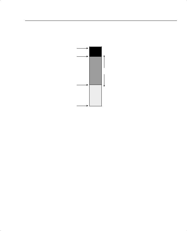
Figure 8-47 illustrates how a CAC decision is made with resource availability indication (RAI).
Figure 8-47 RAI Configuration
100% |
|
High Water Mark |
Gateway Sends RAI Unavailable |
|
Message to Gatekeeper |
Low Water Mark |
Gateway Sends RAI Available |
Message to Gatekeeper |
|
0% |
|
Table 8-36 evaluates the RAI mechanism against the CAC evaluation criteria described earlier in this chapter.
Table 8-36 RAI CAC Evaluation Criteria
Evaluation Criteria |
Value |
|
|
VoX supported |
VoIP only |
|
|
Toll bypass or IP telephony |
Toll bypass |
|
Potentially IP telephony, but CM does not yet support RAI |
|
|
Platforms and releases |
Cisco AS5300 access server: Cisco IOS Release 12.0(5)T |
|
Cisco 2600 and 3600 series routers T1/E1: Cisco IOS |
|
Release 12.1(3)T |
|
|
PBX trunk types supported |
All |
|
|
End to end, local, or IP cloud |
Local at the terminating gateway (DSP and DS0 resources; |
|
algorithm platform dependent) |
|
|
Per call, interface, or endpoint |
Per gateway |
|
|
Topology awareness |
None |
|
|
Guarantees QoS for duration of call |
None |
|
|
Postdial delay |
None |
|
|
Messaging network overhead |
Occasional RAI toggle between gateway and gatekeeper |
|
|
640 Chapter 8: Call Admission Control and QoS Signaling
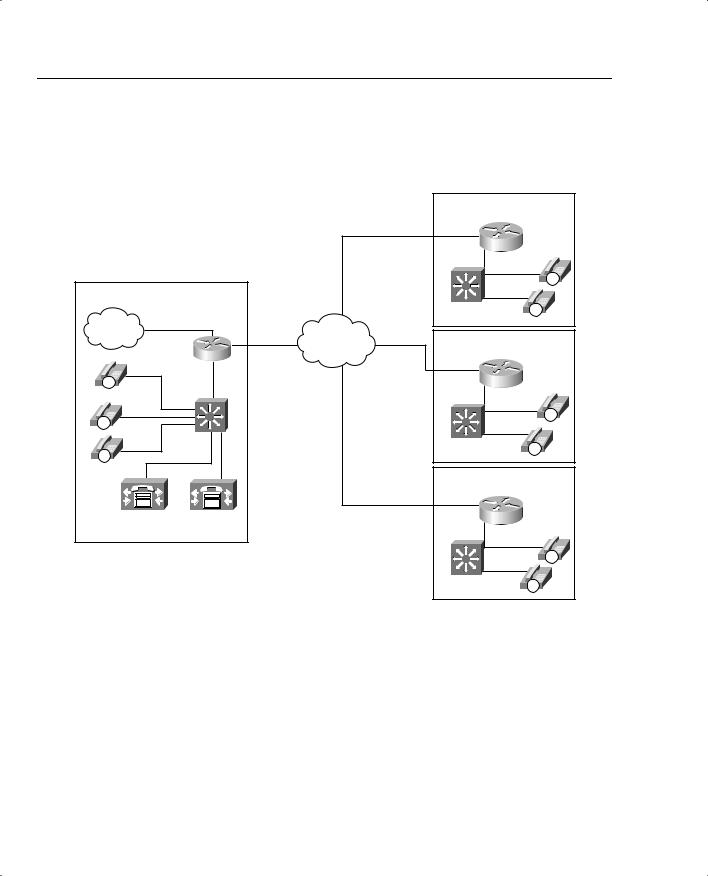
Figure 8-48 illustrates a typical CallManager centralized call-processing model using locations to provide CAC.
Figure 8-48 CallManager Centralized Call-Processing Model with Regions and Locations Defined
|
|
|
|
|
Location: Atlanta |
|
|
|
|
|
256 kbps |
Region: A |
|
|
|
|
|
|
|
|
|
|
|
|
Circuit |
|
|
|
|
|
|
|
|
IP |
|
Host Site |
|
|
|
|
|
|
|
|
|
|
Catalyst |
IP |
|
T1 PRI |
768 kbps |
|
Switch |
|
|
PSTN |
|
|
|
|||
|
|
|
Location: San Jose |
|||
|
|
|
Circuit |
IP WAN |
||
|
|
|
|
Region: B |
|
|
|
|
|
|
256 kbps |
|
|
|
|
|
|
Circuit |
|
|
IP |
|
|
|
|
|
|
IP |
|
|
|
|
|
IP |
|
|
|
|
|
|
|
|
|
Catalyst |
|
|
Catalyst |
IP |
|
|
Switch |
|
|
||
IP |
|
|
|
Switch |
||
|
|
|
|
|
||
|
|
|
|
|
Location: Dallas |
|
|
|
|
|
|
Region: C |
|
CallManager |
CallManager |
|
256 kbps |
|
|
|
|
Circuit |
|
|
|||
Publisher |
Subscriber |
|
|
|
||
|
|
|
|
|||
|
|
|
|
|
|
IP |
|
|
|
|
|
Catalyst |
IP |
|
|
|
|
|
Switch |
|
|
|
|
|
|
|
|
Table 8-37 shows the amount of bandwidth that will be subtracted, per call, from the total allotted bandwidth for a configured region.
Table 8-37 Location-Based CAC Resource Calculations
Codec |
Bandwidth Reserved |
|
|
G.711 |
80 kbps |
|
|
G.729 |
24 kbps |
|
|
G.723 |
24 kbps |
|
|
GSM |
29 kbps |
|
|
Wideband |
272 kbps |
|
|

Foundation Summary 641
Table 8-38 evaluates location-based CAC against the CAC evaluation criteria described earlier in this chapter.
Table 8-38 Location-Based CAC Evaluation Criteria
Evaluation Criteria |
Value |
|
|
VoX supported |
VoIP only |
|
|
Toll bypass or IP telephony |
IP Telephony only |
|
|
Platforms and releases |
CallManager 3.0 |
|
(AAR was added in CallManager release 3.3.) |
|
|
PBX trunk types supported |
None |
|
|
End to end, local, or IP cloud |
End-to-end between originating and terminating location, |
|
although locations have no knowledge of the network topology |
|
in between |
|
|
Per call, interface, or endpoint |
Per call |
|
|
Topology awareness |
None |
|
|
Guarantees QoS for duration of call |
None |
|
|
Postdial delay |
None |
|
|
Messaging network overhead |
None |
|
|
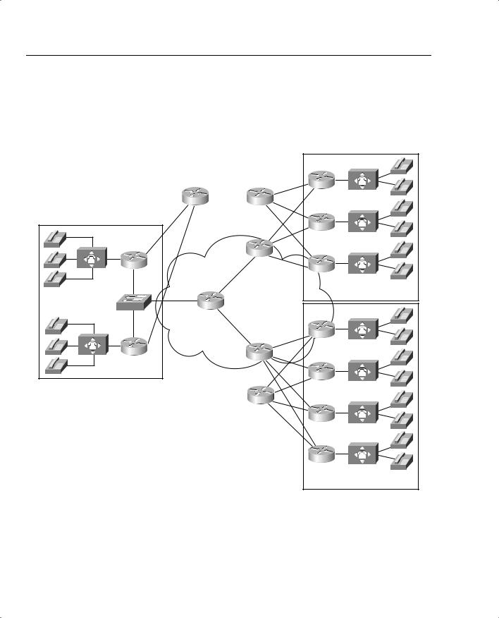
Figure 8-49 shows a single-zone gatekeeper-controlled VoIP network with two gateways that illustrates gatekeeper CAC in its simplest form.
Figure 8-49 Simple Single-Zone Topology
Gatekeeper
R1 |
IP Network |
R2 |
|
Call 1 Is Allowed
Call 2 Is Allowed
Call 3 Is Denied
Foundation Summary 643
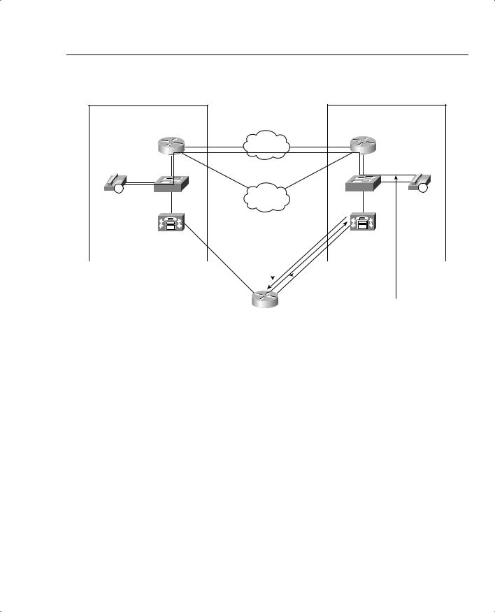
Figure 8-51 Gatekeeper in a CallManager Topology |
|
|
||
|
CallManager |
|
CallManager |
|
|
Cluster A |
|
|
Cluster B |
|
R1 |
IP Network |
R1 |
|
|
|
|
||
IP |
SW1 |
|
SW1 |
IP |
x1111 |
|
PSTN |
|
x2111 |
|
Can I Make a Call? (ARQ) |
||||
CallManager |
|
|
|
|
CallManager |
|
|
|
|
||
Zone 1 |
|
|
|
|
Zone 2 |
|
|
|
|
|
|
|
|
|
|
Yes You Can (ACF) or |
|
|
|
|
|
No You Cannot (ARJ) |
|
Call Is Placed if Allowed
Gatekeeper
Tables 8-39 and 8-40 list the gatekeeper commands and options used to configure gatekeeper zone bandwidth.
Table 8-39 Gatekeeper Bandwidth Command
Command |
Mode and Function |
|
|
bandwidth {interzone | total | session} |
Specifies the gatekeeper zone bandwidth restrictions |
{default | zone zone-name} max- |
|
bandwidth |
|
|
|
bandwidth remote max-bandwidth |
Specifies the total bandwidth for H.323 traffic between |
|
this gatekeeper and any other gatekeeper |
|
|
644 Chapter 8: Call Admission Control and QoS Signaling
Table 8-40 Gatekeeper Bandwidth Command Options
Bandwidth |
|
Command |
|
Options |
Function |
|
|
interzone |
Specifies the total amount of bandwidth for H.323 traffic from the zone to any |
|
other zone. |
|
|
total |
Specifies the total amount of bandwidth for H.323 traffic allowed in the zone. |
|
|
session |
Specifies the maximum bandwidth allowed for a session in the zone. |
|
|
default |
Specifies the default value for all zones. |
|
|
zone |
|
zone-name |
Names the particular zone. |
|
|
max-bandwidth |
Maximum bandwidth. For interzone and total, the range is from 1 to 10,000,000 |
|
kbps. For session, the range is from 1 to 5000 kbps. |
|
|
Table 8-41 evaluates the gatekeeper zone bandwidth mechanism against the CAC evaluation criteria described earlier in this chapter.
Table 8-41 Gatekeeper Zone Bandwidth CAC Evaluation Criteria
Evaluation Criteria |
Value |
|
|
VoX supported |
VoIP/H.323 only |
|
|
Toll bypass or IP telephony |
Toll bypass and IP telephony |
|
(Some caveats exist if both the CallManager and Cisco IOS gateways |
|
are used in the same zone.) |
|
|
Platforms and releases |
Cisco IOS gateways since Release 11.3 |
|
(CM has recent changes in E.164 registration, and bandwidth |
|
requested per call.) |
|
|
PBX trunk types supported |
All |
|
|
End to end, local, or IP cloud |
End-to-end between originating gateway and terminating gateway, |
|
although not aware of the network topology in between |
|
|
Per call, interface, or endpoint |
Per call |
|
|
Topology awareness |
None |
|
|
Guarantees QoS for duration |
None |
of call |
|
|
|
Postdial delay |
None |
|
|
Messaging network overhead |
Part of the gatekeeper RAS messaging |
|
|
Foundation Summary 645
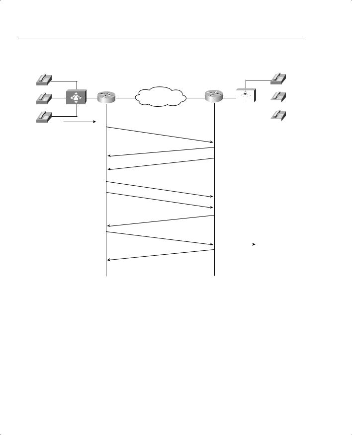
Figure 8-52 shows the flow of RSVP path and resv messages through the network.
Figure 8-52 RSVP Path and Resv Messages
|
|
|
PATH Messages |
|
|
|
|
R2 |
|
R3 |
|
|
|
|
|
|
|
|
|
|
RESV Messages |
||
R1 |
|
|
R4 |
||
|
|
|
|
|
|
|
|
|
|
|
|
|
|
|
|
|
|
|
|
Data Flow |
|
|
||||||
|
|
|
|
|
|
|
|
|
|
|
|
|
|
|
|
|
|
|
|
|
|
|
|
|
|
|
|
|
|
|
|
|
|
Sending |
|
Receiving |
||||||||||||||
Application |
|
Application |
||||||||||||||
Figure 8-53 shows a call flow of the H.323 call setup messages and the RSVP reservation messages.

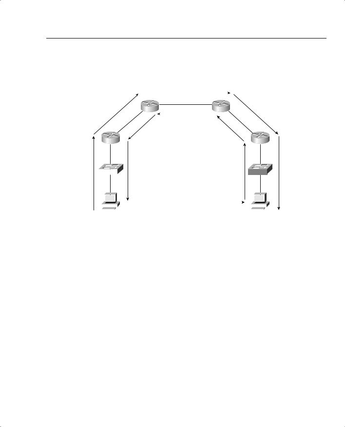
Foundation Summary 647
Table 8-18 summarizes the results of nine call setup scenarios based on the QoS levels that can be configured in the VoIP dial peers at the originating and terminating gateways.
Figure 8-54 illustrates how RSVP uses the priority queue in LLQ for packets matching the voice-like profile.
Figure 8-54 RSVP Packet-Classification Criteria
|
|
|
|
|
Egress Interface / PVC |
||
|
|
|
|
|
|
Queueing (LLQ) |
|
|
|
|
Voice Conforming, Admitted Flows |
|
|
|
|
|
|
|
|
|
|
||
|
|
|
|
Priority |
|
||
|
|
|
|
|
|
|
|
Unclassified |
|
|
|
|
Queue |
|
|
|
|
|
|
|
|
||
Flows |
|
Non-Voice Conforming, Admitted Flows |
|
|
|
||
RSVP |
|
Reserved |
|
||||
|
|
|
|
||||
|
|
|
|
|
|
||
|
|
|
|
|
Queues |
|
|
|
|
Classification |
|
|
|
|
|
|
|
|
|
|
|
|
|
|
|
|
|
|
|
|
|
|
|
|
|
|
|
|
|
|
|
|
|
|
|
Class 1 |
|
|
|
|
|
|
|
|
|
|
|
|
|
|
|
|
|
|
|
|
|
|
|
|
|
|
|
|
|
|
|
Class 2 |
|
|
|
|
Non-Admitted Flows, Voice Signaling |
|
|
|
|
|
|
|
|
|
|
||
|
|
|
|
|
|
||
|
|
|
Traffic, PATH and RESV Messages |
|
Default |
|
|
|
|
|
|
|
|
|
|
|
|
|
|
|
|
Queue |
|
|
|
|
|
|
|
|
|
|
|
|
|
|
|
|
|
Table 8-43 summarizes the bandwidth RSVP allocates for calls using different Cisco IOS gateway codecs.
Table 8-43 RSVP Bandwidth Reservations for Voice Codecs
Codec |
Bandwidth Reserved per Call in LLQ |
|
|
|
|
G.711 |
(A-law and µ-law) |
80 kbps |
|
|
|
G.723.1 and G.723.1A (5.3 kbps) |
22 kbps |
|
|
|
|
G.723.1 and G.723.1A (6.3 kbps) |
23 kbps |
|
|
|
|
G.726 |
(16 kbps) |
32 kbps |
|
|
|
G.726 |
(24 kbps) |
40 kbps |
|
|
|
G.726 |
(32 kbps) |
48 kbps |
|
|
|
G.728 |
|
32 kbps |
|
|
|
G.729 |
(all versions) |
24 kbps |
|
|
|
648 Chapter 8: Call Admission Control and QoS Signaling
Table 8-44 lists the commands used to define and enable RSVP.
Table 8-44 RSVP Profile, req-qos and acc-qos Commands
Command |
Mode and Function |
|
|
ip rsvp pq-profile |
Specifies the criteria for determining which flows go into the |
|
priority queue |
|
|
req-qos {best-effort | controlled-load | |
Specifies the desired quality of services requested to be used |
guaranteed-delay} |
in reaching a specified VoIP dial peer |
|
|
acc-qos {best-effort | controlled-load | |
Specifies the acceptable quality of service for any inbound |
guaranteed-delay} |
and outbound call on a VoIP dial peer |
|
|
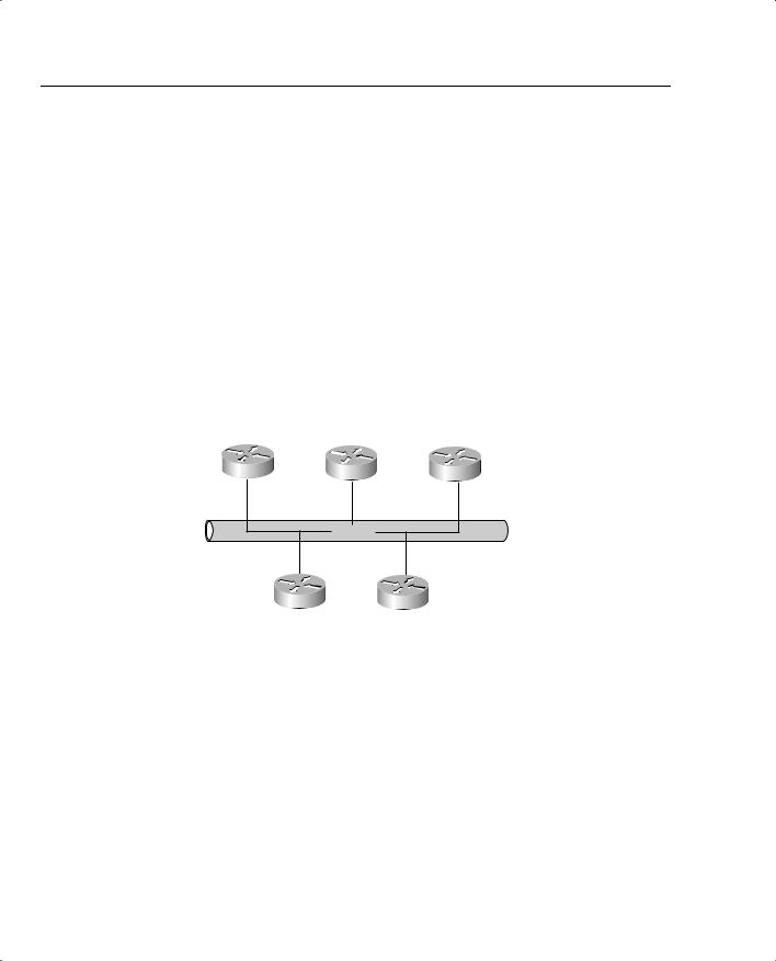
Figure 8-55 shows a managed segment in a Layer 2 domain that interconnects a group of routers.
Figure 8-55 DSBM Managed Subnet
DSBM Client |
DSBM |
DSBM Client |
Ethernet
DSBM Client |
DSBM Client |

Foundation Summary 649
Table 8-45 lists the commands used to enable and define the DSBM in Example 8-18.
Table 8-45 SBM Commands
Command |
Mode and Function |
|
|
ip rsvp bandwidth |
Enables RSVP on an interface |
|
|
ip rsvp dsbm candidate [priority] |
Configures the interface to participate as a contender in the |
|
DSBM dynamic election process, whose winner is based on the |
|
highest priority |
|
|
ip rsvp dsbm non-resv-send-limit |
Configures the average rate, in kbps, for the DSBM candidate |
rate kbps |
|
|
|
ip rsvp dsbm non-resv-send-limit |
Configures the maximum burst size, in KB, for the DSBM |
burst kilobytes |
candidate |
|
|
ip rsvp dsbm non-resv-send-limit |
Configures the peak rate, in kbps, for the DSBM candidate |
peak kbps |
|
|
|
Table 8-46 lists other RSVP commands that can be useful in monitoring and troubleshooting RSVP.
Table 8-46 RSVP Monitoring and Troubleshooting Commands
Command |
Mode and Function |
|
|
show ip rsvp neighbor [interface-type |
Displays current RSVP neighbors |
interface-number] |
|
|
|
show ip rsvp request [interface-type |
Displays RSVP-related request information being |
interface-number] |
requested upstream |
|
|
show ip rsvp reservation [interface-type |
Displays RSVP-related receiver information currently |
interface-number] |
in the database |
|
|
show ip rsvp sbm [detail] [interface-name] |
Displays information about a SBM configured for a |
|
specific RSVP-enabled interface or for all RSVP- |
|
enabled interfaces on the router |
|
|
show ip rsvp sender [interface-type |
Displays Resource Reservation Protocol (RSVP) |
interface-number] |
PATH-related sender information currently in the |
|
database |
|
|

650 Chapter 8: Call Admission Control and QoS Signaling
Table 8-47 evaluates the RSVP mechanism against the CAC evaluation criteria described earlier in this chapter.
Table 8-47 RSVP CAC Evaluation Criteria
Evaluation Criteria |
Value |
|
|
VoX supported |
VoIP/H.323 only |
|
|
Toll bypass or IP telephony |
Currently trunking only |
|
|
Platforms and releases |
Cisco IOS gateways in Release 12.1(5)T and 12.2 |
|
|
PBX trunk types supported |
All |
|
|
End to end, local, or IP cloud |
End to end between originating gateway and terminating |
|
gatekeeper (provided all intermediate nodes are RSVP |
|
configured) |
|
Could be used at WAN edge with DiffServ backbone |
|
|
Per call, interface, or endpoint |
Per call |
|
|
Topology awareness |
Yes |
|
|
Guarantees QoS for duration of call |
Yes |
|
|
Postdial delay |
Yes |
|
|
Messaging network overhead |
Path/resv and periodic keepalives |
|
|
There is little overlap between local CAC mechanisms and those that look ahead to the rest of the network to determine nonlocal conditions. It is easy to understand why the distinct local and nonlocal mechanisms are useful. However, there is considerable overlap between the measurement techniques and the resource reservation techniques of the two nonlocal, lookahead CAC mechanisms. For this reason, there is debate over which is the better method.
Table 8-48 compares the strengths and weaknesses of the measurement-based and resourcebased CAC mechanisms. With this information, you can determine the best method for your individual network.


652 Chapter 8: Call Admission Control and QoS Signaling
Table 8-48 Comparison of Measurement-Based and Resource Reservation-Based CAC Features (Continued)
|
Measurement-Based |
Resource Reservation-Based |
Criteria |
Techniques |
Techniques |
|
|
|
Protecting voice |
The CAC decision is based on probe |
A reservation is established per call |
QoS after |
traffic statistics before the call is |
before the call is admitted. The quality |
admission |
admitted. After admission, the call |
of the call is therefore unaffected by |
|
quality is determined by the |
changes in network traffic conditions. |
|
effectiveness of other QoS |
|
|
mechanisms in the network. |
|
|
|
|
Network traffic |
Periodic probe traffic overhead to a |
RSVP messaging traffic overhead for |
overhead |
cached number of IP destinations. |
every call. |
|
Both the interval and the cache size |
|
|
can be controlled by the configuration. |
|
|
|
|
Scalability |
Sending probes to thousands of |
Individual flow reservation is |
|
individual IP destinations may be |
important on the small-bandwidth |
|
impractical in a large network. Probes |
links around the edge of the network. |
|
can be sent to the WAN edge devices, |
However, individual reservations per |
|
however, which proxy on behalf of |
call flow may not make sense on large- |
|
many more destinations on a high- |
bandwidth links in the backbone such |
|
bandwidth campus network behind |
as an OC-12. Hybrid network |
|
the edge. This provides considerable |
topologies can solve this need, and |
|
scalability, because the WAN is much |
additional upcoming RSVP tools in |
|
more likely to be congested than the |
this space will provide further |
|
campus LAN. |
scalability. |
|
|
|
Table 8-49 summarizes the 11 different voice CAC mechanisms that have been discussed in chapter. It also lists the first Cisco IOS release in which the feature became available.
Table 8-49 Summary of CAC Features
Type |
CAC Feature |
SW Release |
|
|
|
Local |
|
|
|
|
|
|
Physical DS0 limitation |
SW independent |
|
|
|
|
Max-Connections on the dial peer |
11.3 |
|
|
|
|
VoFR Voice-Bandwidth |
12.0.(4)T |
|
|
|
|
Trunk conditioning |
12.1.(2)T |
|
|
|
|
Local Voice Busyout (LVBO) |
12.1.(2)T |
|
|
|
Measurement based |
|
|
|
|
|
|
Advanced Voice Busyout (AVBO) |
12.1.(3)T |
|
|
|
|
PSTN fallback |
12.1.(3)T |
|
|
|

|
|
|
|
|
|
|
|
|
|
Foundation Summary 653 |
||
|
|
|
|
|
|
|
|
|
|
|
|
|
Table 8-49 Summary of CAC Features (Continued) |
|
|
|
|
|
|
|
|||||
|
|
|
|
|
|
|
|
|
|
|
|
|
|
Type |
|
CAC Feature |
|
|
|
SW Release |
|
|
|||
|
|
|
|
|
|
|
|
|
|
|
|
|
|
Resource based |
|
|
|
|
|
|
|
|
|
|
|
|
|
|
|
|
|
|
|
|
|
|
|
|
|
Resource calculation |
|
|
|
|
|
|
|
|
|
|
|
|
|
|
|
|
|
|
|
|
|
|
|
|
|
|
|
Resource availability indication |
|
12.0.(5)T (AS5300) |
|
||||||
|
|
|
|
|
|
|
|
|
12.1.(3)T (2600/3600) |
|
||
|
|
|
|
|
|
|
|
|
|
|
|
|
|
|
|
CallManager location-based CAC |
|
CallManager 3.0 |
|
|
|||||
|
|
|
|
|
|
|
|
|
AAR was added in CallManager |
|||
|
|
|
|
|
|
|
|
|
release 3.3 |
|
|
|
|
|
|
|
|
|
|
|
|
|
|
|
|
|
|
|
Gatekeeper zone bandwidth |
|
11.(3) (local zone) |
|
||||||
|
|
|
|
|
|
|
|
|
12.1.(5)T (interzone) |
|
||
|
|
|
|
|
|
|
|
|
|
|
|
|
|
Resource reservation |
|
|
|
|
|
|
|
|
|
|
|
|
|
|
|
|
|
|
|
|
|
|
|
|
|
|
|
Resource Reservation Protocol |
|
12.1.(5)T |
|
|
|||||
|
|
|
|
|
|
|
|
|
|
|
||
|
Table 8-50 summarizes the voice technologies supported by the CAC methods discussed in this |
|||||||||||
|
chapter. |
|
|
|
|
|
|
|
|
|
|
|
Table 8-50 Summary of Voice Technologies supported |
|
|
|
|
|
|
||||||
|
|
|
|
|
|
|
|
|
|
|
|
|
|
|
|
|
VoIP |
|
VoIP |
VoIP |
|
|
|
|
H.323 |
|
Feature |
|
H.323 |
|
SIP |
MGCP |
VoFR |
VoATM |
CM |
Video |
||
|
|
|
|
|
|
|
|
|
|
|||
|
Physical DS0 limitation |
Yes |
|
Yes |
Yes |
Yes |
Yes |
No |
No |
|||
|
|
|
|
|
|
|
|
|
|
|
||
|
Max-Connections |
|
Yes |
|
Yes |
Yes |
Yes |
Yes |
No |
No |
||
|
|
|
|
|
|
|
|
|
|
|
||
|
Voice-Bandwidth |
|
No |
|
No |
No |
Yes |
No |
No |
No |
||
|
|
|
|
|
|
|
|
|
|
|
||
|
Trunk conditioning |
|
Yes |
|
Yes |
Yes |
Yes |
Yes |
No |
No |
||
|
|
|
|
|
|
|
|
|
|
|
||
|
Local Voice Busyout |
|
Yes |
|
Yes |
Yes |
Yes |
Yes |
No |
No |
||
|
|
|
|
|
|
|
|
|
|
|||
|
Advanced Voice Busyout |
Yes |
|
Yes |
Yes |
No |
No |
No |
No |
|||
|
|
|
|
|
|
|
|
|
|
|
||
|
PSTN fallback |
|
Yes |
|
Yes |
Yes |
No |
No |
No |
No |
||
|
|
|
|
|
|
|
|
|
|
|
||
|
Resource availability |
|
Yes |
|
No |
No |
No |
No |
No |
No |
||
|
indication |
|
|
|
|
|
|
|
|
|
|
|
|
|
|
|
|
|
|
|
|
|
|
||
|
CallManager locations |
|
Yes |
|
No |
Yes |
Yes |
Yes |
Yes |
No |
||
|
|
|
|
|
|
|
|
|
|
|
||
|
Gatekeeper zone |
|
Yes |
|
No |
No |
No |
No |
Yes |
Yes |
||
|
bandwidth |
|
|
|
|
|
|
|
|
|
|
|
|
|
|
|
|
|
|
|
|
|
|
||
|
Resource Reservation |
|
Yes |
|
No |
No |
No |
No |
No |
No |
||
|
Protocol |
|
|
|
|
|
|
|
|
|
|
|
|
|
|
|
|
|
|
|
|
|
|
|
|