

22 Chapter 1: QoS Overview
Network Delay
Most people draw a big cloud for a Frame Relay or ATM network, because the details are not typically divulged to the customer. However, the same types of delay components seen outside the cloud also exist inside the cloud—and the engineer that owns the routers and switches outside the cloud cannot exercise as much QoS control over the behavior of the devices in the cloud.
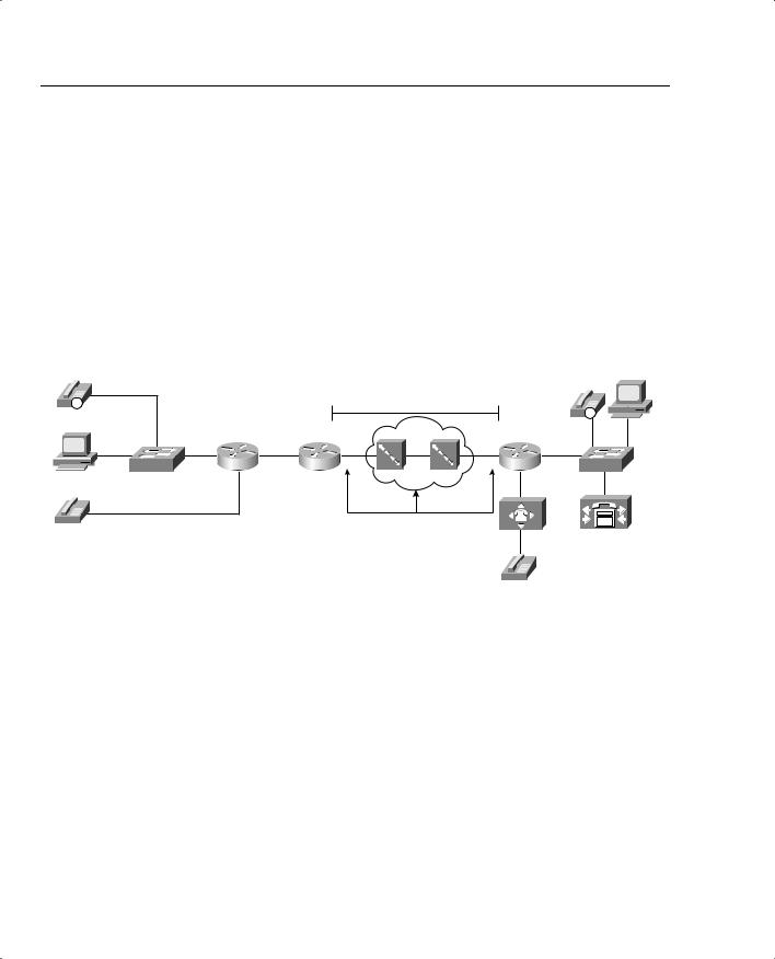
So how much delay should a packet experience in the cloud? Well, it will vary. The carrier might commit to a maximum delay value as well. However, with a little insight, you can get a solid understanding of the minimum delay a packet should experience through a Frame Relay cloud. Consider Figure 1-11, focusing on the Frame Relay components.
Figure 1-11 Frame Relay Network: Propagation and Serialization Delay Components
|
|
|
|
|
Propagation Delay - Educated |
|
|
Server 1 |
|
|
|
|
|
|
|
|
|
||
|
|
|
|
|
Guess Based on Distance from |
|
|
||
IP |
|
|
|
|
R2 to R3 |
|
|
|
|
|
|
|
|
|
|
|
|
IP |
|
|
|
|
|
|
|
|
|
|
|
Hannah |
|
|
|
|
|
|
|
|
|
|
|
|
|
|
|
|
|
|
FA0/0 |
SW1 |
R1 |
s0 |
s0 |
R2 |
s1 |
T1 |
s0/0 |
R3 |
SW2 |
Serialization Delay
201
301
The propagation delay and serialization delay can be guessed pretty closely. No matter how many switches exist between R2 and R3, the cumulative propagation delays on all the links between R2 and R3 will be at least as much as the propagation delay on a point-to-point circuit. And with most large providers, because they have many points of presence (PoPs), the Frame Relay VC probably takes the same physical route as a point-to-point circuit would anyway. As for serialization delay, the two slowest links, by far, will be the two access links (in most cases). Therefore, the following account for most of the serialization delay in the cloud:
•The serialization delay to send the packet into the cloud
•The serialization delay at the egress Frame Relay switch, sending the packet to R3

QoS: Tuning Bandwidth, Delay, Jitter, and Loss 23
Suppose, for example, that R2 and R3 are 1000 km apart, and a 1500-byte packet is sent. The network delay will at least be the propagation delay plus both serialization delays on the two access links:
Propagation = 1000 km / 2.1 * 108 = 4.8 ms
Serialization (ingress R2) = 1500 bytes * 8 / 128,000 bps = 94 ms
Serialization (egress R3) = 1500 bytes * 8 / 1,544,000 = 7.8 ms
For a total of 106.6 ms delay
Of course, the delay will vary—and will depend on the provider, the status of the network’s links, and overall network congestion. In some cases, the provider will include delay limits in the contracted service-level agreement (SLA).
Queuing delay inside the cloud creates the most variability in network delay, just as it does outside the cloud. These delays are traffic dependent, and hard to predict.
NOTE To QoS test takers: Neither the QoS nor DQoS course books list network delay as a delay component. Because it does affect delay, however, it is included here.
Delay Summary
Of the types of delay covered so far in this chapter, all except shaping delay occur in every network. Shaping delay occurs only when shaping is enabled.
Two other delay components may or may not be found in a typical network. First, codec delay will be experienced by voice and video traffic. Codec delay is covered in more depth in the section titled “Voice Delay Considerations.” Compression requires processing, and the time taken to process a packet to compress or decompress the packet introduces delay. Chapter 7, “Link-Efficiency Tools,” covers compression delay.
Table 1-6 summarizes the delay components listed in this section.
Table 1-6 Components of Delay Not Specific to One Type of Traffic
Delay Component |
Definition |
Where It Occurs |
|
|
|
Serialization delay |
Time taken to place all bits of a frame |
Outbound on every physical |
(fixed) |
onto the physical medium. Function of |
interface; typically negligible on |
|
frame size and physical link speed. |
T3 and faster links. |
|
|
|
Propagation delay |
Time taken for a single bit to traverse the |
Every physical link. Typically |
(fixed) |
physical medium from one end to the |
negligible on LAN links and |
|
other. Based on the speed of light over |
shorter WAN links. |
|
that medium, and the length of the link. |
|
|
|
|
continues
24 Chapter 1: QoS Overview
Table 1-6 Components of Delay Not Specific to One Type of Traffic (Continued)
Delay Component |
Definition |
Where It Occurs |
|
|
|
Queuing delay |
Time spent in a queue awaiting the |
Possible on every output interface. |
(variable) |
opportunity to be forwarded (output |
Input queuing unlikely in routers, |
|
queuing), or awaiting a chance to cross |
more likely in LAN switches. |
|
the switch fabric (input queuing). |
|
|
|
|
Forwarding or |
Time required from receipt of the |
On every piece of switching |
processing delay |
incoming frame, until the frame/packet |
equipment, including routers, |
(variable) |
has been queued for transmission. |
LAN switches, Frame Relay |
|
|
switches, and ATM switches. |
|
|
|
Shaping delay |
Shaping (if configured) delays |
Anywhere that shaping is |
(variable) |
transmission of packets to avoid packet |
configured, which is most likely on |
|
loss in the middle of a Frame Relay or |
a router, when sending packets to a |
|
ATM network. |
Frame Relay or ATM network. |
|
|
|
Network delay |
Delays created by the components of the |
Inside the service provider’s |
(variable) |
carrier’s network when using a service. |
network. |
|
For instance, the delay of a Frame Relay |
|
|
frame as it traverses the Frame Relay |
|
|
network. |
|
|
|
|
QoS Tools That Affect Delay
Several QoS features can help with delay issues. You’ll find more detail about each of these tools in various chapters throughout this book. For now, however, knowing what each class of QoS tool accomplishes will help you sift through some of the details.
The best QoS tool for delay issues is . . . more bandwidth—again! More bandwidth helps bandwidth-related problems, and it also helps delay-related problems. Faster bandwidth decreases serialization delay. Because packets exit more quickly, queuing delay decreases. Higher CIR on your VCs reduces shaping delay. In short, faster bandwidth reduces delay!
Unfortunately, more bandwidth does not solve all delay problems, even if you could afford more bandwidth! In fact, in converged networks (networks with voice, video, and data), adding more bandwidth might mask delay problems that are best solved through other QoS tools or through better QoS design. The sections that follow address the QoS tools can affect the delay a particular packet receives.
Queuing (Scheduling)
The most popular QoS tool, queuing, involves choosing the packets to be sent based on something other than arrival time. In other words, instead of FIFO queuing with one queue, other queuing mechanisms create multiple queues, place packets into these different queues, and then
QoS: Tuning Bandwidth, Delay, Jitter, and Loss 25
pick packets from the various queues. As a result, some packets leave the router more quickly, with other packets having to wait longer. Although queuing does not decrease delay for all packets, it can decrease delay for delay-sensitive packets, and increase delay for delay-insensitive packets—and enabling a queuing mechanism on a router does not cost any cash, whereas adding more bandwidth does.
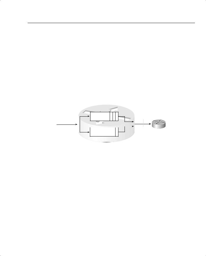
Each queuing method defines some number of different queues, with different methods of scheduling the queues—in other words, different rules for how to choose from which queue the next packet to be sent will be chosen. Figure 1-12 depicts a queuing mechanism with two queues. Suppose Hannah sent four packets, but the fourth packet was sent by a videoconferencing package she was running, whereas the other three packets were for a web application she was using while bored with the video conference.
Figure 1-12 Sample Queuing Method: Two Queues
4 X 1500
Byte Packets
R1
Output Queue 1
3 2 1 |
Output Queue 2 |
|
|
R2 |
|
|||
|
|
|
4
R1 could notice that packet 4 has different characteristics, and place it into a different queue. Packet 4 could exit R1 before some or all of the first three packets.
Link Fragmentation and Interleaving
The time required to serialize a packet on a link is a function of the speed of the link, and the size of the packet. When the router decides to start sending the first bit of a packet, the router continues until the whole packet is sent. Therefore, if a delay-sensitive packet shows up just after a long packet has begun to be sent out an interface, the delay-sensitive packet must wait until the longer packet has been sent.
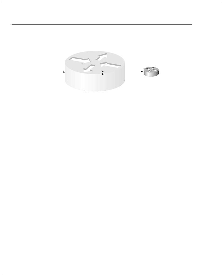
Suppose, for example, that two packets have arrived at R1. Packet 1 is 1500 bytes, and packet 2 is 200 bytes. The smaller packet is delay sensitive. Because packet 2 arrived just after the first bit of packet 1 was sent, packet 2 must wait 214 ms for packet 1 to be serialized onto the link. With link fragmentation and interleaving (LFI), packet 1 could be broken into three 500-byte fragments, and packet 2 could be interleaved (inserted) and sent on the link after the first of the three fragments of packet 1. Figure 1-13 depicts LFI operation.
26 Chapter 1: QoS Overview
Figure 1-13 Link Fragmentation and Interleaving
|
|
|
|
|
|
|
R1 |
|
|
|
|
|
|
|
|
|
|
|
|
|
Output Queue 1: 3 Fragments |
|
|
|
|
|
|
||||||||||
Packet 1: 1500 |
of Packet #1 Shown |
|
|
|
|
|
|
|
|
|
|
|
||||||
|
P1 |
P1 |
P1 |
|
|
|
|
|
|
|
|
|
|
|
|
|||
Bytes, Arrives |
|
|
|
|
Output Queue 1 |
|
|
|
||||||||||
First |
|
F3 |
F2 |
F1 |
|
|
|
|
P1 |
P1 |
2 |
P1 |
|
|
|
|
||
|
|
Output Queue 2 |
|
|
|
|
|
|
R2 |
|||||||||
|
|
|
|
|||||||||||||||
Packet 2: 200 |
|
|
|
F3 |
F2 |
|
F1 |
|
|
|
||||||||
|
|
|
|
|
|
|
|
|
|
|
|
|
||||||
Bytes, Delay |
|
2 |
|
|
|
|
|
|
|
|
|
|
|
|
||||
|
|
|
|
|
|
|
|
|
|
|
|
|||||||
Sensitive, |
|
|
|
|
|
|
|
|
|
|
|
|
|
|
|
|
|
|
Arrives Second |
|
|
|
|
|
|
|
|
|
|
|
|
|
|
|
|
|
|
Legend: Px Fy Means Packet Number x, Fragment Number y
Note that packet 1 was fragmented into three pieces. Because packet 2 arrived after packet 1 had begun to be sent, packet 2 had to wait. With LFI, packet 2 does not have to wait for the entire original packet, but rather it waits for just 1 fragment to be sent.
Compression
Compression takes a packet, or packet header, and compresses the data so that it uses fewer bits. Therefore, a 1500-byte packet, compressed to 750 bytes, takes half as much serialization time as does an uncompressed 1500-byte packet.
Compression reduces serialization delay, because the number of bits used to send a packet is decreased. However, delay may also be increased because of the processing time required to compress and decompress the packets. Chapter 7 covers the pros and cons of each type of compression.
Traffic Shaping
Traffic shaping actually increases delay, in an effort to reduce the chance of packet loss. Shaping is mentioned here just because of its negative impact on delay.
Although adding more bandwidth always helps, the tools summarized in Table 1-7 do help to improve the effects of delay in a network.
Table 1-7 QoS Tools That Affect Delay
Type of QoS Tool |
How It Affects Delay |
|
|
Queuing |
Enables you to order packets so that delay-sensitive packets leave their queues |
|
more quickly than delay-insensitive packets. |
|
|
Link fragmentation |
Because routers do not preempt a packet that is currently being transmitted, |
and interleaving |
LFI breaks larger packets into smaller fragments before sending them. |
|
Smaller delay-sensitive packets can be sent after a single smaller fragment, |
|
instead of having to wait for the larger original packet to be serialized. |
|
|