


36 Chapter 1: QoS Overview
Table 1-12 Comparing Voice Payload to Voice Signaling: QoS Requirements
|
Bandwidth |
Delay |
Jitter |
Loss |
|
|
|
|
|
Voice Payload |
Low |
Low |
Low |
Low |
|
|
|
|
|
Voice Signaling |
Low |
Low |
Medium |
Medium |
|
|
|
|
|
QoS tools can treat voice payload differently than they treat voice signaling. To do so, each QoS tool first classifies voice packets into one of these two categories. To classify, the QoS tool needs to be able to refer to a field in the packet that signifies that the packet is voice payload, voice signaling, or some other type of packet. Table 1-13 lists the various protocols used for signaling and for voice payload, defining documents, and identifying information.
Table 1-13 Voice Signaling and Payload Protocols
Protocol |
Documented By |
Useful Classification Fields |
|
|
|
H.323/H.225 |
ITU |
Uses TCP port 1720 |
|
|
|
H.323/H.245 |
ITU |
TCP ports 11xxx |
|
|
|
H.323/H.245 |
ITU |
TCP port 1720 (Fast Connect) |
|
|
|
H.323/H.225 RAS |
ITU |
TCP port 1719 |
|
|
|
Skinny |
Cisco |
TCP ports 2000-2002 |
|
|
|
Simple Gateway Control Protocol |
|
TCP ports 2000-2002 |
(SGCP) |
|
|
|
|
|
Media Gateway Control Protocol |
RFC 2705 |
UDP port 2427, TCP port 2428 |
(MGCP) |
|
|
|
|
|
Intra-Cluster Communications |
Cisco |
TCP ports 8001–8002 |
Protocols (ICCP) |
|
|
|
|
|
Real-Time Transport Protocol (RTP) |
RFC 1889 |
UDP ports 16384–32767, even ports |
|
|
only |
|
|
|
Real-Time Control Protocol (RTCP) |
RFC 1889 |
UDP ports 16385–32767, odd ports |
|
|
only; uses RTP port + 1 |
|
|
|
The next few sections of this book examine voice more closely in relation to the four QoS characteristics: bandwidth, delay, jitter, and loss.
Voice Bandwidth Considerations
Voice calls create a flow with a fixed data rate, with equally spaced packets. Voice flows can be described as isochronous, which, according to Dictionary.com, means “characterized by or occurring at equal intervals of time.” Consider Figure 1-19, where a call has been placed between analog phones at extensions 201 and 301.
Traffic Characteristics of Voice, Video, and Data 37
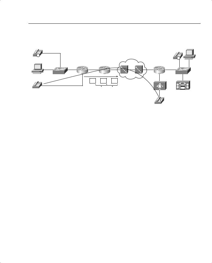
Figure 1-19 Isochronous Packet Flow for Voice Call
Server 1
IP |
|
|
|
|
|
|
|
|
|
|
|
|
|
|
|
|
|
|
IP |
Hannah |
|
|
|
|
|
|
|
|
|
|
|
|
|
|
|
|
|
|
FA0/0 |
SW1 |
R1 |
s0 |
s0 |
R2 |
s1 |
T1 |
s0/0 |
R3 |
SW2 |
|
|
RTP |
|
RTP |
RTP |
|
|
|
|
201 |
|
|
20 ms |
20 ms |
|
|
|
|
|
|
|
|
|
|
|
|
|
|
|
301
R1 creates the IP/UDP/RTP voice payload packets and sends them, by default, every 20 ms. Because Cisco IOS Software places 20 ms of encoded voice into each packet, a packet must be sent every 20 ms. So, how much bandwidth is really needed for the voice payload call? Well, actual bandwidth depends on several factors:
•
•
•
•
Codec
Packet overhead (IP/UDP/RTP)
Data-link framing (depends on data links used)
Compression
Most people quote a G.711 call as taking 64 kbps, and a G.729 call as taking 8 kbps. Those bandwidth numbers consider the payload only—ignoring data-link, IP, UDP, and RTP headers. Consider Table 1-14, with actual bandwidth requirements for various types of voice calls.
Table 1-14 Bandwidth Requirements with Various Data-Link Types
L2 Header |
L2 |
IP/UDP/RTP |
|
Payload |
Total |
Type |
Header Size |
Header Size |
Codec |
Bandwidth |
Bandwidth |
|
|
|
|
|
|
Ethernet |
14 |
40 bytes |
G.711 |
64 kbps |
85.6 |
|
|
|
|
|
|
MLPPP/FR |
6 |
40 bytes |
G.711 |
64 kbps |
82.4 |
|
|
|
|
|
|
Ethernet |
14 |
40 bytes |
G.729 |
8 kbps |
29.6 |
|
|
|
|
|
|
MLPPP/FR |
6 |
40 bytes |
G.729 |
8 kbps |
26.4 |
|
|
|
|
|
|
*For DQOS test takers: These numbers are extracted from the DQOS course.

38 Chapter 1: QoS Overview
The bandwidth requirements vary dramatically based on the codec and the compression effect if RTP header compression is used. Compressed RTP (cRTP) actually compresses the IP/UDP/ RTP headers, with dramatic reduction in bandwidth when used with lower bit-rate codecs. With G.711, because a large percentage of the bandwidth carries the payload, cRTP helps, but the percentage decrease in bandwidth is not as dramatic. In either case, cRTP can increase delay caused while the processor compresses and decompresses the headers.
NOTE Although other codecs are available, this book compares G.711 and G.729 in most examples, noting any conditions where a different specific codec may need different treatment with QoS.
ATM can add a significant amount of data-link overhead to voice packets. Each ATM cell has 5 bytes of overhead; in addition, the last cell holding parts of the voice packet may have a lot of wasted space. For instance, a voice call using G.729 will have a packet size of 60 bytes. ATM adds about 8 bytes of framing overhead, and then segments the 68-byte frame into two cells— one using the full 48 bytes of ATM cell payload, and the other only using 20 bytes of the cell payload area—with 28 bytes “wasted.” Therefore, to send one voice “packet” of 60 bytes, two cells, in total 106 bytes, must be sent over ATM. One option to lessen the overhead is to change the payload size to contain 30 ms of voice with a G.729 codec—which interestingly also only takes two ATM cells.
Voice Activity Detection (VAD) also affects the actual bandwidth used for a voice payload call. VAD causes the sender of the voice packets to not send packets when the speaker is silent. Because human speech is typically interactive (I know there are some exceptions to that rule that come to mind right now!), VAD can decrease the actual bandwidth by about 60 percent. The actual amount of bandwidth savings for each call cannot be predicted—simple things such as calling from a noisy environment defeats VAD. Also VAD can be irritating to listeners. After a period of not speaking, the speaker starts to talk. The VAD logic may perform front-end speech clipping, which means that the first few milliseconds of voice are not sent.
Note that the numbers shown in the previous table, Table 1-14, come directly from the DQOS course (and several other sources inside Cisco). Interestingly, the numbers ignore data-link trailer overhead, and ignore ATM and 802.1Q framing. One of the technical editors of this book graciously provided an alternative, more accurate table that you should consider using for planning in production networks. For the exam, trust the numbers in Table 1-14. Table 1-15 lists the updated numbers.

Traffic Characteristics of Voice, Video, and Data 39
Table 1-15 Updated Bandwidth Requirements for Various Types of Voice Calls
|
|
|
|
|
ATM (Variable |
|
|
|
|
|
Bytes of L2 |
Bandwidth |
802.1Q |
|
|
|
Overhead, |
Consumption, |
Ethernet (32 |
PPP (9 |
MLP (13 |
Frame-Relay |
Depending on |
Including L2 |
Bytes of L2 |
Bytes of L2 |
Bytes of L2 |
(8 Bytes of L2 |
Cell-Padding |
Overhead |
Overhead) |
Overhead) |
Overhead) |
Overhead) |
Requirements) |
|
|
|
|
|
|
G.711 at 50 pps* |
93 kbps |
84 kbps |
86 kbps |
84 kbps |
106 kbps |
|
|
|
|
|
|
G.711 at 33 pps |
83 kbps |
77 kbps |
78 kbps |
77 kbps |
84 kbps |
|
|
|
|
|
|
G.729A at 50 pps |
37 kbps |
28 kbps |
30 kbps |
28 kbps |
43 kbps |
|
|
|
|
|
|
G.729A at 33 pps |
27 kbps |
21 kbps |
22 kbps |
21 kbps |
28 kbps |
|
|
|
|
|
|
*pps = packets per second
Voice Delay Considerations
Voice call quality suffers when too much delay occurs. The symptoms include choppy voice, and even dropped calls. Interactivity also becomes difficult—ever had a call on a wireless phone, when you felt like you were talking on a radio? “Hey Fred, let’s go bowling—OVER”— “Okay, Barney, let’s go while Betty and Wilma are out shopping—OVER.” With large delays, it sometimes becomes difficult to know when it is your turn to talk.
Voice traffic experiences delays just like any other packet, and that delay originates from several other sources. For a quick review on delay components covered so far, consider the delay components listed in Table 1-16.
Table 1-16 Components of Delay Not Specific to One Type of Traffic
Delay |
|
|
Component |
Definition |
Where It Occurs |
|
|
|
Serialization delay |
Time taken to place all bits of a frame |
Outbound on every physical interface; |
|
onto the physical medium. Function of |
typically negligible on T3 and faster |
|
frame size and physical link speed. |
links. |
|
|
|
Propagation delay |
Time taken for a single bit to traverse |
Every physical link. Typically negligi- |
|
the physical medium from one end to |
ble on LAN links and shorter WAN |
|
the other. Based on the speed of light |
links. |
|
over that medium, and the length of the |
|
|
link. |
|
|
|
|
Queuing delay |
Time spent in a queue awaiting the |
Possible on every output interface. |
|
opportunity to be forwarded (output |
Input queuing unlikely in routers, more |
|
queuing), or awaiting a chance to cross |
likely in LAN switches. |
|
the switch fabric (input queuing). |
|
|
|
|
continues
40 Chapter 1: QoS Overview
Table 1-16 Components of Delay Not Specific to One Type of Traffic (Continued)
Delay |
|
|
Component |
Definition |
Where It Occurs |
|
|
|
Forwarding or |
Time required from receipt of the |
On every piece of switching |
processing delay |
incoming frame until the frame/packet |
equipment, including routers, LAN |
|
has been queued for transmission. |
switches, Frame Relay switches, and |
|
|
ATM switches. |
|
|
|
Shaping delay |
Shaping (if configured) delays trans- |
Anywhere that shaping is configured, |
|
mission of packets to avoid packet loss |
which is most likely on a router, when |
|
in the middle of a Frame Relay or ATM |
sending packets to a Frame Relay or |
|
network. |
ATM network. |
|
|
|
Network delay |
Delays created by the components of |
Inside the service provider’s network. |
|
the carrier’s network when using a |
|
|
service. For instance, the delay of a |
|
|
Frame Relay frame as it traverses the |
|
|
Frame Relay network. |
|
|
|
|
Figure 1-20 shows an example of delay concepts, with sample delay values shown. When the delay is negligible, the delay is just listed as zero.
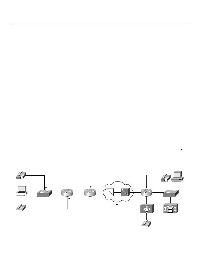
Figure 1-20 Example Network with Various Delay Components Shown: Left-to-Right Directional Flow
Delays for Packets Flowing Left-to-Right: Total Delay: 94 ms
Forwarding: 0 |
Forwarding: 0 |
Queuing: 0 |
Queuing: 15 |
Serialization: 0 |
Serialization: 4 |
|
Propagation: .5 |
IP
Hannah
|
|
|
|
|
|
|
|
|
|
|
|
|
|
|
|
|
|
|
|
|
|
|
|
|
|
|
|
|
|
|
|
SW1 |
R1 s0 s0 R2 s1 |
|
|
|
|
|
|
|
|
|
|
|
|||
|
|
|
|
|
|
|
|||||
|
|
|
|
|
|
|
|
|
|
|
|
|
|
|
|
|
|
|
|
|
|
|
|
|
|
|
|
|
|
|
|
|
|
|
|
|
|
|
|
|
|
|
|
|
|
|
|
Forwarding: 0
Queuing: 0
Serialization: 0 Server 1
Propagation: 0
|
|
|
IP |
|
|
|
FA0/0 |
T1 |
s0/0 |
R3 |
SW2 |
201
Forwarding: 0 |
Network: 50 |
|
|
|
Queuing: 15 |
(Note: Do Not Count |
|
|
|
Serialization: 9 |
R2 Serialization Here |
|
|
|
|
|
|
||
|
|
|
||
|
|
|
||
Propagation: .5 |
and at R2!) |
|
|
|
|
|
|
301

Traffic Characteristics of Voice, Video, and Data 41
The figure lists sample delay values. The values were all made up, but with some basis in reality. Forwarding delays are typically measured in microseconds, and become negligible. The propagation delay from R1 to R2 is calculated based on a 100-km link. The serialization delays shown were calculated for a G.729 call’s packet, no compression, assuming PPP as the datalink protocol. The queuing delay varies greatly; the example value of 15 ms on R1’s 56-kbps link was based on assuming a single 105-byte frame was enqueued ahead of the packet whose delay we are tracking—which is not a lot of queuing delay. The network delay of 50 ms was made up—but that is a very reasonable number. The total delay is only 94 ms—to data network engineers, the delay seems pretty good.
So is this good enough? How little delay does the voice call tolerate? The ITU defines what it claims to be a reasonable one-way delay budget. Cisco has a slightly different opinion. You also may have applications where the user tolerates large delays to save cash. Instead of paying $3 per minute for a quality call to a foreign country, for instance, you might be willing to tolerate poor quality if the call is free. Table 1-17 outlines the suggested delay budgets.
Table 1-17 One-Way Delay Budget Guidelines
1-Way Delay (in ms) |
Description |
|
|
0–150 |
ITU G.114’s recommended acceptable range |
|
|
0–200 |
Cisco’s recommended acceptable range |
|
|
150–400 |
ITU G.114’s recommended range for degraded service |
|
|
400+ |
ITU G.114’s range of unacceptable delay in all cases |
|
|
With the example in Figure 1-20, the voice call’s delay fits inside the G.114 recommended delay budget. However, voice traffic introduces a few additional delay components, in addition to the delay factors that all data packets experience:
•
•
•
Codec delay
Packetization delay
De-jitter buffer delay (initial playout delay)
Be warned—many books and websites use different terms to refer to the component parts of these three voice-specific types of delay. The terms used in this book are consistent with the Cisco courses, and therefore with the exams.
Codec delay and packetization delay coincide with each other. To get the key concepts of both, consider Figure 1-21, which asks the question, “How much delay happens between when the human speaks, and when the IP packets are sent?”

42 Chapter 1: QoS Overview
Figure 1-21 Codec and Packetization Delays Between the Instant the Speaker Speaks and When the Packet Holding the Speech Is Sent
How Much Time Lags Between
When Human Speaks and
Packets Are Sent?
 Packets Created by IP Phone
Blah Blah
RTP
Blah
IP
SW2
R1 |
R2 |
IP
Consider what has to happen at the IP Phones before a packet can be sent. The caller dials digits, and the call is set up. When the call is set up, the IP Phone starts sending RTP packets. When these packets begin, they are sent every 20 ms (default)—in other words, each packet has 20 ms of voice inside the voice payload part of the packet. But how much time passes between when the speaker makes some sound and when the voice packet containing that sound is first sent?
Consider sounds waves for an instant. If you and I sit in the same room and talk, the delay from when you speak and when I hear it is very small, because your voice travels at the speed of sound, which is roughly 1000 km per hour. With packet telephony, the device that converts from sound to analog electrical signals, then to digital electrical signals, and then puts that digital signal (payload) into a packet, needs time to do the work. So there will be some delay between when the speaker speaks and when the IP/UDP/RTP payload packet is sent. In between when the speaker talks and when a packet is sent, the following delays are experienced:
•
•
Packetization delay
Codec delay
Packetization Delay
The IP Phone or voice gateway must collect 20 ms of voice before it can put 20 ms worth of voice payload into a packet. (The defaults for G.711 and G.729 on IP Phones and Cisco IOS Software gateways are to put 20 ms of voice into an RTP packet; the value can be changed.)
Therefore, for the sake of discussion in this book, we consistently consider packet delay always to be 20 ms in examples. That is, the speaker must talk for 20 ms before a packet containing 20 ms of voice can be created.

Traffic Characteristics of Voice, Video, and Data 43
Codec Delay
Codec delay has two components:
•The time required to process an incoming analog signal and convert it to the correct digital equivalent
•A feature called look-ahead
With the first component of codec delay, which is true for all codecs, the IP Phone or gateway must process the incoming analog voice signal and encode the digital equivalent based on the codec in use. For instance, G.729 processes 10 ms of analog voice at a time. That processing does take time—in fact, the actual conversion into G.729 CS-ACELP (Conjugate Structure Algebraic Code Excited Linear Predictive) takes around 5 ms. Some documents from Cisco cite numbers between 2.5 and 10 ms, based on codec load.
The codec algorithm may cause additional delays due to a feature called look-ahead. Lookahead occurs when the codec is predictive—in other words, one method of using fewer bits to encode voice takes advantage of the fact that the human vocal cords cannot instantaneously change from one sound to a very different sound. By examining the voice speech, and knowing that the next few ms of sound cannot be significantly different, the algorithm can use fewer bits to encode the voice—which is one way to improve from 64-kbps G.711 to an 8-kbps G.729 call. However, a predictive algorithm typically requires the codec to process some voice signal that will be encoded, plus the next several milliseconds of voice. With G.729, for example, to process a 10-ms voice sample, the codec must have all of that 10 ms of voice, plus the next 5 ms, in order to process the predictive part of the codec algorithm.
So, the G.729a codec delays the voice as follows, for each 10-ms sample, starting with the time that the 10 ms to be encoded has arrived:
5 ms look-ahead + 5 ms processing (average) = 10 ms
Remember, codec delay is variable based on codec load. The white paper, “Understanding Delay in Packet Voice Networks,” at Cisco.com provides more information about this topic (www.cisco.com/warp/public/788/voip/delay-details.html).
Considering the Effects of Packetization and Codec Delay
You need to consider packetization delay and codec delay together, because they do overlap. For instance, packetization delay consumes 20 ms while waiting on 20 ms of voice to occur. But what else happens in the first 20 ms? Consider Table 1-18, with a timeline of what happens, beginning with the first uttered sound in the voice call.
44 Chapter 1: QoS Overview
Table 1-18 Typical Packetization and Codec Delay Timeline—G.729
Timeline |
Action |
Codec Delay |
Packetization Delay |
|
|
|
|
T=0 |
Begin collecting voice |
Not begun yet (by this book’s |
Begins |
|
samples for A/D |
definition) |
|
|
conversion, encoding |
|
|
|
|
|
|
T=10 |
Collected complete 10-ms |
Codec delay begins |
10 ms so far; packeti- |
|
sample, which will be |
|
zation delay continues |
|
encoded with G.729 |
|
|
|
|
|
|
T=15 |
Collected first 5 ms of |
5 ms so far; G.729 now has the |
15 ms so far; packeti- |
|
second 10-ms sample |
5-ms look-ahead that the |
zation delay continues |
|
|
algorithm needs to encode first |
|
|
|
10 ms sample |
|
|
|
|
|
T=20 |
Finished collecting second |
10 ms so far; codec delay |
Packetization delay |
|
10-ms sample |
finished for first 10-ms |
complete at 20 ms, |
|
|
sample; second 10-ms sample |
because 20 ms of voice |
|
|
in memory; codec delay for |
has been collected |
|
|
second sample begins |
|
|
|
|
|
T=25 |
Collected first 5 ms of |
5-ms delay so far on second |
Finished with packeti- |
|
third 10-ms sample |
10-ms sample; 15 ms total; |
zation delay; 20 ms |
|
|
G.729 now has the 5-ms look- |
voice has been |
|
|
ahead that the algorithm needs |
received |
|
|
to encode second 10-ms |
|
|
|
sample |
|
|
|
|
|
T=30 |
Finished collecting third |
20 ms total codec delay; RTP |
Finished. 20 ms total |
|
10-ms sample |
and payload ready to be sent |
|
|
|
|
|
Total delays |
|
20 ms |
20 ms |
for first packet |
|
|
|
|
|
|
|
Notice that the packetization and codec delays overlap. Although each takes 20 ms, because there is overlap, the packet actually experiences about 30 ms of total delay instead of a total of 40 ms.
De-Jitter Buffer Delay
De-jitter buffer delay is the third voice delay component. Jitter happens in data networks. You can control it, and minimize it for jitter-sensitive traffic, but you cannot eliminate it. Buy why talk about jitter in the section on delay? Because a key tool in defeating the effects of jitter, the de-jitter buffer (sometimes called the jitter buffer) actually increases delay.
The de-jitter buffer collects voice packets and delays playing out the voice to the listener, to have several ms of voice waiting to be played. By doing so, if the next packet experiences jitter

Traffic Characteristics of Voice, Video, and Data 45
and shows up late, the de-jitter buffer’s packets can be played out isochronously, so the voice sounds good. This is the same tool used in your CD player in your car—the CD reads ahead several seconds, knowing that your car will hit bumps, knowing that the CD temporarily will not be readable—but having some of the music in solid-state memory lets the player continue to play the music. Similarly, the de-jitter buffers “reads ahead” by collecting some voice before beginning playout, so that delayed packets are less likely to cause a break in the voice.
The de-jitter buffer must be filled before playout can begin. That delay is called the initial playout delay and is depicted in Figure 1-22.
Figure 1-22 De-Jitter Buffer Initial Playout Delay, No Jitter in First Three Packets
|
|
|
|
|
|
|
De-Jitter Buffer |
|
|
|
|||
T=0 – No |
|
|
|
|
|
|
|
|
|
No Playout of Voice |
|||
Packets |
|
|
|
|
|
|
|
|
|
|
|
|
|
Received Yet |
|
|
|
|
|
|
|
|
|
|
|
|
|
for This Call |
|
|
|
|
|
|
|
|
|
|
|
|
|
T=X – Instant |
|
|
|
|
|
De-Jitter Buffer |
|
|
|
||||
|
|
|
|
|
|
|
|
|
|
|
|
||
That First |
|
|
|
|
|
|
|
20 ms Voice Payload |
No Playout of Voice |
||||
Packet Has |
|
|
|
|
|
|
|
||||||
|
|
|
|
|
|
|
– Packet 1 |
||||||
|
|
|
|
|
|
|
|
|
|
||||
Been Received |
|
|
|
|
|
|
|
|
|
|
|
|
|
|
|
|
|
|
|
|
|
|
|
|
|
||
T=X+20–Instant |
|
|
|
|
|
De-Jitter Buffer |
|
|
|
||||
That Second |
|
|
|
|
|
|
|
|
|
|
|
|
|
|
|
|
|
20 ms Voice Payload |
|
20 ms Voice Payload |
|
|
|
|
|||
Packet Has Been |
|
|
|
|
|
|
No Playout of Voice |
||||||
|
|
|
|
– Packet 2 |
|
|
– Packet 1 |
|
|||||
Received, NO |
|
|
|
|
|
|
|
|
|
|
|||
|
|
|
|
|
|
|
|
|
|
|
|
|
|
JITTER |
|
|
|
|
|
|
|
|
|
|
|
|
|
T=X+40–Instant |
|
|
|
|
|
De-Jitter Buffer |
|
|
|
||||
That Third Packet |
|
|
|
|
|
|
|
|
|
|
|
|
|
|
|
|
|
20 ms Voice Payload |
20 ms Voice Payload |
|
|
|
|
||||
Has Been Received, |
|
|
|
|
|
Playing out Packet 1 |
|||||||
|
|
|
|
– Packet 3 |
|
– Packet 2 |
|
||||||
NO JITTER |
|
|
|
|
|
|
|
|
|
||||
|
|
|
|
|
|
|
|
|
|
|
|
|
|
In this figure, the de-jitter buffer shows the initial playout delay. The time difference between when the initial packet arrives, and when the third packet arrives, in this particular case, is 40 ms. (Cisco IOS gateways default to 40 ms of initial playout delay.) In fact, if the initial playout delay were configured for 40 ms, this delay would be 40 ms, regardless of when the next several packets arrive. Consider, for instance, Figure 1-23, which gives a little insight into the operation of the de-jitter buffer.
In Figure 1-23, the playout begins at the statically set playout delay interval—40 ms in this case—regardless of the arrival time of other packets. A 40-ms de-jitter playout delay allows jitter to occur—because we all know that jitter happens—so that the played-out voice can continue at a constant rate.
46 Chapter 1: QoS Overview
Figure 1-23 De-Jitter Buffer Initial Playout Delay, 10 ms Jitter for Third Packet
T=0 – No |
|
|
|
|
De-Jitter Buffer |
|
|
|
||||
|
|
|
|
|
|
|
|
No Playout of Voice |
||||
Packets |
|
|
|
|
|
|
|
|
||||
|
|
|
|
|
|
|
|
|
|
|
||
Received Yet |
|
|
|
|
|
|
|
|
|
|
|
|
for This Call |
|
|
|
|
|
|
|
|
|
|
|
|
T=X – Instant |
|
|
|
|
De-Jitter Buffer |
|
|
|
||||
|
|
|
|
|
|
|
|
No Playout of Voice |
||||
That First |
|
|
|
|
|
|
20 ms Voice Payload |
|||||
|
|
|
|
|
|
|
|
|
||||
Packet Has |
|
|
|
|
|
|
– Packet 1 |
|
|
|
||
Been Received |
|
|
|
|
|
|
|
|
|
|||
|
|
|
|
|
|
|
|
|
|
|
||
T=X+20 – Instant |
|
|
|
|
De-Jitter Buffer |
|
|
|
||||
That Second |
|
|
|
|
|
|
|
|
|
No Playout of Voice |
||
|
|
|
|
20 ms Voice Payload |
|
20 ms Voice Payload |
|
|||||
Packet Has Been |
|
|
|
|
|
|
|
|
|
|||
|
|
|
|
– Packet 2 |
|
– Packet 1 |
|
|
|
|
||
Received, NO |
|
|
|
|
|
|
|
|
|
|||
|
|
|
|
|
|
|
|
|
|
|
|
|
|
|
|
|
|
|
|
|
|
|
|
|
|
JITTER |
|
|
|
|
|
|
|
|
|
|
|
|
T=X+40 – 3rd |
|
|
|
|
|
De-Jitter Buffer |
|
|
|
|||
|
|
|
|
|
|
|
|
|
Playing out Packet 1 |
|||
|
|
|
|
|
|
|
20 ms Voice Payload |
|
||||
Packet Not |
|
|
|
|
|
|
|
|
|
|
|
|
Received Yet |
|
|
|
|
|
|
|
– Packet 2 |
|
|
|
|
T=X+50 – 3rd |
|
|
|
|
|
De-Jitter Buffer |
|
|
|
|||
|
|
|
|
|
|
|
|
|
Playing out Last 10 |
|||
Packet Received; |
|
|
|
|
20 ms Voice Payload |
|
20 ms Voice Payload |
|
ms of Packet 1 |
|||
|
|
|
|
– Packet 3 |
|
– Packet 2 |
|
|||||
Had +10 Jitter |
|
|
|
|
|
|
||||||
|
|
|
|
|
|
|
|
|
||||
|
|
|
|
|
|
|
|
|
|
|
|
|
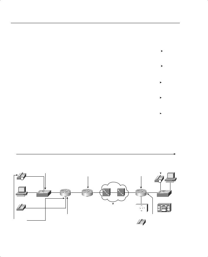
Figure 1-24 summarizes all the delay components for a voice call. This figure repeats the same example delay values as did Figure 1-20, but with voice-specific delays added for codec, packetization, and de-jitter delays shown.
Figure 1-24 Complete End-to-End Voice Delay Example
Delays for Packets Flowing Left-to-Right: Total Delay: 164 ms
Forwarding: 0 |
Forwarding: 0 |
Queuing: 0 |
Queuing: 15 |
Serialization: 0 |
Serialization: 4 |
|
Propagation: .5 |
IP |
|
|
|
|
|
Hannah |
|
|
|
|
|
SW1 |
R1 |
s0 |
s0 |
R2 |
s1 |
201 |
Forwarding: 0 |
|
|
|
|
|
|
|
|
||
Codec: 10 |
Queuing: 15 |
|
|
|
|
Serialization: 9 |
|
|
|
||
Packetization: 20 |
|
|
|
||
Propagation: .5 |
|
|
|||
|
|
|
|||
Forwarding: 0 De-jitter: 40 ms |
||
Queuing: 0 |
|
Server 1 |
|
||
Serialization: 0 |
|
|
Propagation: 0 |
|
|
|
|
|
IP |
|
|
|
FA0/0 |
T1 |
s0/0 |
R3 |
SW2 |
|
|
|
|
|
|
|
|
|
|
|
|
|
|
|
|
|
|
|
|
|
|
|
|
|
|
|
Network: 50 |
|
De-jitter: 40 ms |
||||||
(Note: Do Not Count |
|
|
|
|
|
|||
R2 Serialization Here |
|
|
|
|
|
|||
|
|
|
|
|
||||
and at R2!) |
|
|
|
|
|
|
|
|
|
|
|
|
|
|
|
||
|
|
|
|
|
|
|
||
301

Traffic Characteristics of Voice, Video, and Data 47
The delay has crept beyond the acceptable limits of one-way delay, according to G.114, but slightly under the limit of 200 ms suggested by Cisco. Without the additional voice delays, the 150-ms delay budget seemed attainable. With 30 ms of codec and packetization delay, however, and a (reasonable) default of 40-ms de-jitter delay (actually, de-jitter initial playout delay), 70 ms of that 150/200-ms delay is consumed. So, what can you do to stay within the desired delay budget? You attack the variable components of delay. Table 1-19 lists the different delay components, and whether they are variable.
Table 1-19 Delay Components, Variable and Fixed
Delay |
Fixed or |
|
QoS Tools |
Component |
Variable |
Comments |
That Can Help |
|
|
|
|
Codec |
Fixed |
Varies slightly based on codec |
None. |
|
|
and processing load; considered |
|
|
|
fixed in course books (and |
|
|
|
probably on exams). Typically |
|
|
|
around 10 ms. |
|
|
|
|
|
Packetization |
Fixed |
Some codecs require a 30-ms |
None. |
|
|
payload, but packetization delay |
|
|
|
does not vary for a single codec. |
|
|
|
Typically 20 ms, including when |
|
|
|
using G.711 and G.729. |
|
|
|
|
|
Propagation |
Variable |
Varies based on length of circuit. |
Move your facilities to the |
|
|
About 5 ms/100 km |
same town. |
|
|
|
|
Queuing |
Variable |
This is the most controllable |
Queuing features, particularly |
|
|
delay component for packet |
those with a priority-queuing |
|
|
voice |
feature. |
|
|
|
|
Serialization |
Fixed |
It is fixed for voice packets, |
Fragmentation and |
|
|
because all voice packets are of |
compression. |
|
|
equal length. It is variable based |
|
|
|
on packet size for all packets. |
|
|
|
|
|
Network |
Variable |
Least controllable variable |
Shaping, fragmentation, |
|
|
component. |
designs mindful of reducing |
|
|
|
delay. |
|
|
|
|
De-jitter buffer |
Variable |
This component is variable |
Configurable playout delay in |
(initial playout delay) |
|
because it can be configured for |
IOS gateways; not |
|
|
a different value. However, that |
configurable in IP Phones. |
|
|
value, once configured, remains |
|
|
|
fixed for all calls until another |
|
|
|
value is configured. In other |
|
|
|
words, the initial playout delay |
|
|
|
does not dynamically vary. |
|
|
|
|
|