


166 Chapter 3: Classification and Marking
LAN Class of Service (CoS)
Many LAN switches today can mark and react to a Layer 2 3-bit field called the Class of Service (CoS) located inside an Ethernet header. The CoS field only exists inside Ethernet frames when 802.1Q or Inter-Switch Link (ISL) trunking is used. You can use the field to set 8 different binary values, which can be used by the classification features of other QoS tools, just like IP precedence and DSCP.
Figure 3-3 shows the general location of the CoS field inside ISL and 802.1P headers.
Figure 3-3 LAN CoS Fields
ISL User Field (1 byte)
|
Frame Type |
|
CoS |
||||
|
|
|
|
|
|
|
|
|
|
|
|
|
|
|
|
ISL Header |
ISL Header (26 Bytes |
|
|
|
|
|
Original Frame |
|
|||||||||||||
|
|
|
|
|
|
|
|
|
|
|
|
|
|
|
|
|
|
|
|
|
|
802.1Q/P |
Dest. |
|
Src |
|
Ether |
|
Tag |
||||||||||||||
|
|
|
|||||||||||||||||||
|
|
Type |
|
||||||||||||||||||
Header |
|
|
|
|
|
|
|
|
|
|
|
|
|
|
|
|
|
|
|
||
|
|
|
|
|
|
|
|
|
|
|
|
|
|
|
|
|
|
|
|
|
|
|
|
|
|
|
|
|
|
|
|
|
|
|
|
|
|
|
|
|
|
|
|
|
|
|
|
|
|
|
|
|
|
|
|
|
|
|
|
|
|
|
|
|
|
|
|
|
|
User |
|
|
|
|
VLAN ID |
|
|
||||||||||
|
|
|
|
Priority |
|
|
|
|
|
||||||||||||
|
|
|
|
|
|
|
|
|
|
|
|
|
|
|
|
|
|
|
|||
|
|
|
|
|
|
|
|
|
|
|
|
|
|
|
|
|
|
|
|
|
|
802.1Q Tag Field (2 bytes)
The term CoS really refers to two different fields—a field inside either the 802.1Q trunking header, or a field inside the ISL header. The IEEE 802.1Q standard uses the 3 most-significant bits of the 2-byte Tag Control field, called the user-priority bits. The Cisco proprietary ISL specification uses the 3 least-significant bits from the 1-byte User field, which is found inside the ISL header’s user field byte. In general conversation, and in the QoS courses from Cisco, the term CoS applies to either of these two fields.
When can CoS be marked, and when can it be useful for classification to a QoS tool? First of all, trunking with 802.1Q or ISL must be enabled before the CoS field even exists! Second, as soon as the packet experiences Layer 3 forwarding, either with a router or some Layer 3 switch, the old LAN header gets discarded—which means you lose the CoS field. After a CoS field has been created and populated with the desired markings, routers and switches have several QoS tools that can react to these markings. Consider, for instance, a typical trunking environment, as shown in Figure 3-4, where all LAN switches are only performing Layer 2 switching.
Classification and Marking Concepts 167
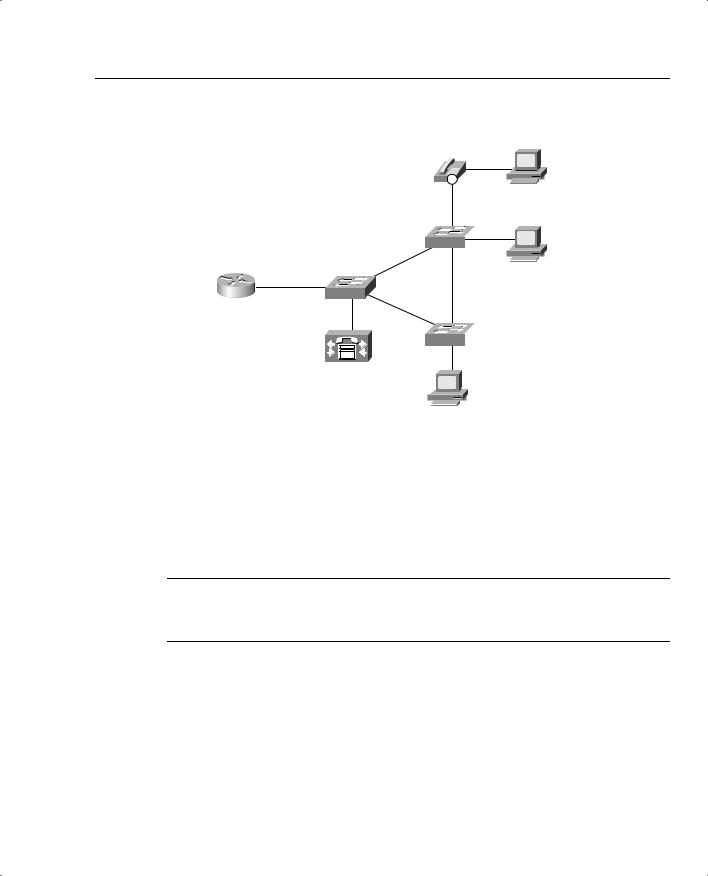
Figure 3-4 CoS—Trunking Locations in a Typical Network, Layer 2 Switches Only
IP
311
Client2
SW3 
Server1
|
FA0/0 |
R3 |
SW2 |
SW4 
Client1
To mark the CoS bits, trunking must be used—and in Figure 3-4, trunking could be used on every Ethernet segment. Switches typically use trunking on the Ethernet segments to other switches, routers, and to IP Phones. Typically, switches do not need to use trunking on segments connected to PCs or servers. Because some networking cards have the capability to support 802.1Q or ISL trunking, however, servers and PCs can set the CoS bits.
NOTE Trunking requires a Fast Ethernet interface, or Gigabit, or 10 Gigabit—it is not supported over 10-Mbps Ethernet. This book does not distinguish among the different types of Ethernet upon each mention.
Both routers and switches use QoS tools that can react to the marked CoS bits. Cisco routers can indeed mark CoS bits for frames exiting an Ethernet interface that supports trunking. For instance, R3 could mark CoS 5 on a frame it forwards out its FA 0/0 interface. Other Cisco router QoS tools can react to the marked CoS bits on incoming frames as well. For instance, R3 could mark packets entering its FA0/0 interface with a particular DSCP value based on the incoming CoS value. Later in this chapter, you will see a sample configuration for class-based marking that performs both of these functions.

168 Chapter 3: Classification and Marking
Cisco switches vary widely regarding their capabilities to set CoS bits and react to previously marked CoS bits. Switches can support marking of CoS, and more often today support marking of IP precedence and DSCP as well. LAN switches that do support QoS features generally perform output queuing, and sometimes input queuing, choosing queues based on CoS values. Congestion avoidance using Weighted Random Early Detection (WRED) is another typical switch QoS feature. In addition, some switches support policing tools, also based on CoS. Although campus QoS is not covered in depth on the QoS exams today, it is an important topic, particularly with converged voice, video, and data networks. Chapter 10, “LAN QoS,” covers LAN QoS in additional depth.
Other Marking Fields
You can use single-bit fields in Frame Relay and ATM networks to mark a frame or cell for Layer 2 QoS. Unlike IP precedence, IP DSCP, and 802.1P/ISL CoS, however, these two fields are not intended for general, flexible use. Each of these single-bit fields, when set, imply that the frame or cell is a better candidate to be dropped, as compared with frames or cells that do not have the bit set. In other words, you can mark the bit, but the only expected action by another QoS tool is for the tool to drop the frame or cell.
Frame Relay defines the discard eligibility (DE) bit, and ATM defines the cell loss priority (CLP) bit. The general idea is that when a device, typically a WAN switch, experiences congestion, it needs to discard some frames or cells. If a frame or cell has the DE or CLP bit set, respectively, the switch may choose to discard those frames or cells, and not discard other frames or cells.
If the DE or CLP bit is set, there is no requirement that the Frame Relay and ATM switches react to it—just like there is no guarantee that an IP packet with DSCP EF will get special treatment by another router. It’s up to the owner of the Frame Relay or ATM switch to decide whether it will consider the DE and CLP bits, and how to react differently.
You can use two other QoS marking fields in specialized cases. The MPLS Experimental bits comprise a 3-bit field that you can use to map IP precedence into an MPLS label. This allows MPLS routers to perform QoS features indirectly based on the original IP Precedence field inside the IP packets encapsulated by MPLS, without the need to spend resources to open the IP packet header and examine the IP Precedence field.
Finally, the QoS Group field, an internal marking that exists only within the router, may be set as a packet passes through the fabric of a Cisco gigabit switch router (GSR) or edge services router (ESR). QoS processing can be performed more quickly inside the switching fabric by using the QoS group. Therefore, you may want to configure GSRs and ESRs to mark the QoS group on ingress so that QoS processing occurs more rapidly.
Summary of Marking Fields
Not all these marked fields receive the same amount of attention on the QoS exams. Refer to the Introduction of this book, and the website suggested there, for the latest information about where to focus your attention. Table 3-5 summarizes the marking fields.

Classification and Marking Concepts 169
Table 3-5 |
Names of Marking Fields |
|
|
|
|
|
|
|
|
|
Field |
Location |
Length |
Comments |
|
|
|
|
|
|
IP Precedence |
IP header |
3 bits |
Contained in the first 3 bits of the ToS |
|
|
|
|
byte. |
|
|
|
|
|
|
IP DSCP |
IP header |
6 bits |
Contained in the first 6 bits of the DS |
|
|
|
|
field, which replaces the ToS byte. |
|
|
|
|
|
|
DS |
IP header |
1 byte |
Replaces ToS byte per RFC 2475. |
|
|
|
|
|
|
ToS |
IP header |
1 byte |
Replaced by DS field per RFC 2475. |
|
|
|
|
|
|
ToS |
IP header |
4 bits |
A field inside the ToS byte; superseded |
|
|
|
|
by RFC 2475. |
|
|
|
|
|
|
CoS |
ISL and 802.1Q/P |
3 bits |
Cisco convention uses “CoS” to |
|
|
|
|
describe either trunking headers’ QoS |
|
|
|
|
field. |
|
|
|
|
|
|
Priority bits |
802.1Q/P |
3 bits |
The name used by IEEE 802.1P for the |
|
|
|
|
CoS bits. |
|
|
|
|
|
|
Discard Eligible (DE) |
Frame Relay |
1 bit |
Frame Relay switches may discard DE- |
|
|
header |
|
marked frames, avoiding discarding |
|
|
|
|
frames without DE marked, under |
|
|
|
|
congestion. |
|
|
|
|
|
|
Cell Loss Priority (CLP) |
ATM cell header |
1 bit |
ATM equivalent of the DE bit |
|
|
|
|
|
|
MPLS Experimental |
MPLS header |
3 bits |
Used to pass QoS marking information |
|
values(s) |
|
|
across an MPLS network. |
|
|
|
|
|
|
QoS Group |
Headers internal |
N/A |
Uses values between 1–99 inclusive. |
|
|
to IOS |
|
Used for marking only internal to a |
|
|
|
|
single router, specifically only on the |
|
|
|
|
GSR/ESR product lines. |
|
|
|
|
|
The names of the various marking fields can be confusing. Quality of service (QoS) does not refer to any specific marking field, but it is a term that refers to a broad set of tools that effect bandwidth, delay, jitter, and loss. In other words, this whole book is about QoS. Class of service (CoS) refers to both of the two 3-bit fields in Ethernet trunking headers—one in the ISL header, and one in the 802.1Q trunking header. However, CoS also refers to a 2-bit field inside Systems Network Architecture (SNA) Layer 3 headers, which is also used for QoS functions. Type of service (ToS) is my personal favorite—ToS is the 1-byte field in the IP header, which includes a 3-bit Precedence field, and 4 ToS bits. And of course, DiffServ re-defines the ToS Byte as the DS-byte, with the DSCP field in the first 6 bits. Make sure you remember the true meanings of QoS, CoS, ToS, Precedence, and DSCP.
170 Chapter 3: Classification and Marking
Classification and Marking Design Choices
Classification and marking tools provide many options, but sometimes sorting out the best way to use the tools can be difficult. Classification and marking tools can classify based on a large number of frame and packet header fields. They can also mark a number of fields, the most notable being the IP Precedence and DSCP fields. You can use the classification and marking tools on all routers in the network, on many LAN switches, and even on IP Phones and host computers. This brief section discusses some of the classification and marking design choices.
The first step in making good classification and marking design choices is to choose where to mark. The general rule for choosing where to mark is as follows:
Mark as close to the ingress edge of the network as is possible.
Figure 3-5 diagrams a typical enterprise IP network, which will be used to look more closely at the options for where to mark packets.
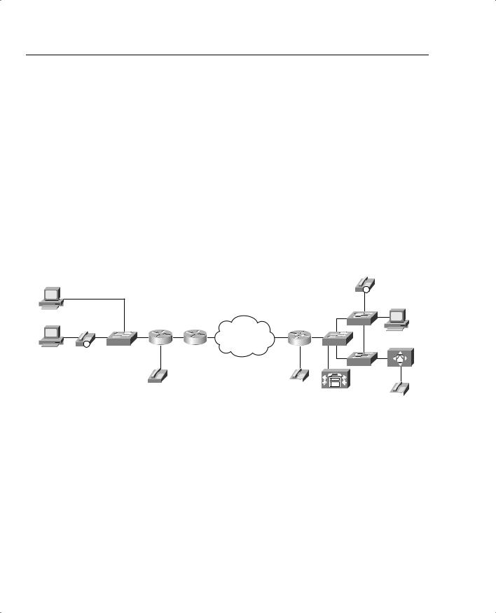
Figure 3-5 Typical Enterprise Network
|
|
|
|
|
311 |
Jessie |
|
|
|
|
|
|
|
|
|
|
IP |
Hannah |
|
|
|
|
SW3 |
|
SW1 |
R1 |
R2 |
Frame Relay |
Server1 |
IP |
R3 |
SW2 |
|||
1251 |
|
|
|
|
|
|
|
|
|
|
SW4 |
|
|
|
|
|
|
1201 |
1301 |
|
|
|
|
|
|
|
|
|
|
1351
Consider packets that flow left to right in Figure 3-5. Hannah and Jessie, both client PCs, can mark IP precedence, IP DSCP, and CoS if their Ethernet card supports ISL or 802.1Q. The IP Phone internally marks its own voice bearer traffic precedence 5, DSCP EF, and CoS 5 by default, its own voice signaling traffic precedence 3, DSCP 31, and CoS 3. The phone can also re-mark the CoS, precedence, and DSCP sent by Hannah’s PC. (The phone default action is to re-mark 0 for all three values.) SW1, depending on the type of switch, might be able to remark CoS, re-mark precedence or DSCP, or make general (multifield) classification and marking decisions—in other words, it might be able to look at some of the fields listed earlier in Tables 3-2 and 3-3. Finally, R1 can use general multifield classification and marking before sending the packet over the WAN—but over the next link to R2, because the link is a PPP link, the only marking options would be in the IP header.

Classification and Marking Concepts 171
So marking can be done in many places near the ingress edge of the network—but whom do you trust? Classification and marking should not be performed before the frame/packet reaches a trusted device. This location in the network is called the trust boundary. For instance, Jessie formerly marked her packets with DSCP default, but because the user of the PC can change that value, Jessie changed to use DSCP EF to get better service. In most cases, the end-user PCs are beyond the trust boundary. IP Phones can reset CoS, precedence, and DSCP to 0 for Hannah’s traffic, and mark the VoIP with CoS 5, precedence 5, and DSCP EF—with the added benefit that the phone user cannot reset those values. The IP Phone trust settings are controlled by the connected Cisco Catalyst switch, enabling the system administrator to trust markings received from the IP Phone while rewriting the values received from the attached PC.
The final consideration when deciding where to mark involves the function of the various devices, and personal preferences. For instance, IP Phones provide three classes—one for voice bearer traffic, one for voice signaling traffic, and one for all packets from the PC. However, a network may need multiple classes for data traffic, so further classification may be required by a switch or router. Some switches provide robust Layer 3 QoS classification and marking func- tions—in these cases, classification and marking may be performed on the switch; otherwise classification and marking must be performed on the router. Figure 3-6 outlines some of the strategies for classification and marking for three different LAN topologies.
Figure 3-6 shows three typical paths for frames between the end-user device and the first router. The first instance shows a typical installation near the end users—a switch that performs only Layer 2 QoS, and PCs connected to it. Only Layer 2 QoS just means that the switch can react to, or possibly set, CoS, but it cannot react to or mark IP precedence or DSCP. In this case, classification and marking is typically performed as packets enter R1’s Ethernet interface. In addition, because SW1 can support CoS, but not precedence or DSCP, R1 may want to map incoming CoS values to the Precedence or DSCP fields.
The second part of Figure 3-6 shows a network with a Layer 3 QoS-capable switch. Depending on the type of switch, this switch may not be able to perform Layer 3 switching, but it does have the capability to react to or mark IP precedence or DSCP. In this case, you should classify and mark on the switch. Classification and marking on the Layer 3 switch allows classification and marking closer to the trust boundary of the network, and offers the added benefits of queuing, congestion avoidance, and policing based on the marked values. If only a few sites in the network have Layer 3 QoS-capable switches, you may prefer to perform classification and marking on the router, so all sites’ configurations are similar. However, classifying and marking in the router places additional overhead on the router’s CPU.
Finally, the third example shows a PC cabled through an IP Phone to a Layer 3 QoS-capable switch. The IP Phone can easily take care of classification and marking into two categories— voice and nonvoice. The switch and router can take advantage of those marked values. If more classes are needed for this network’s QoS policy, SW3, or R3, can perform classification and marking. Of course, if the QoS policy for this network only requires the three classes—one for voice bearer traffic, one for voice signaling traffic, one for nonvoice—and all PCs are connected through the switch in the IP Phone, no classification and marking is needed on SW3 or R3!
172 Chapter 3: Classification and Marking
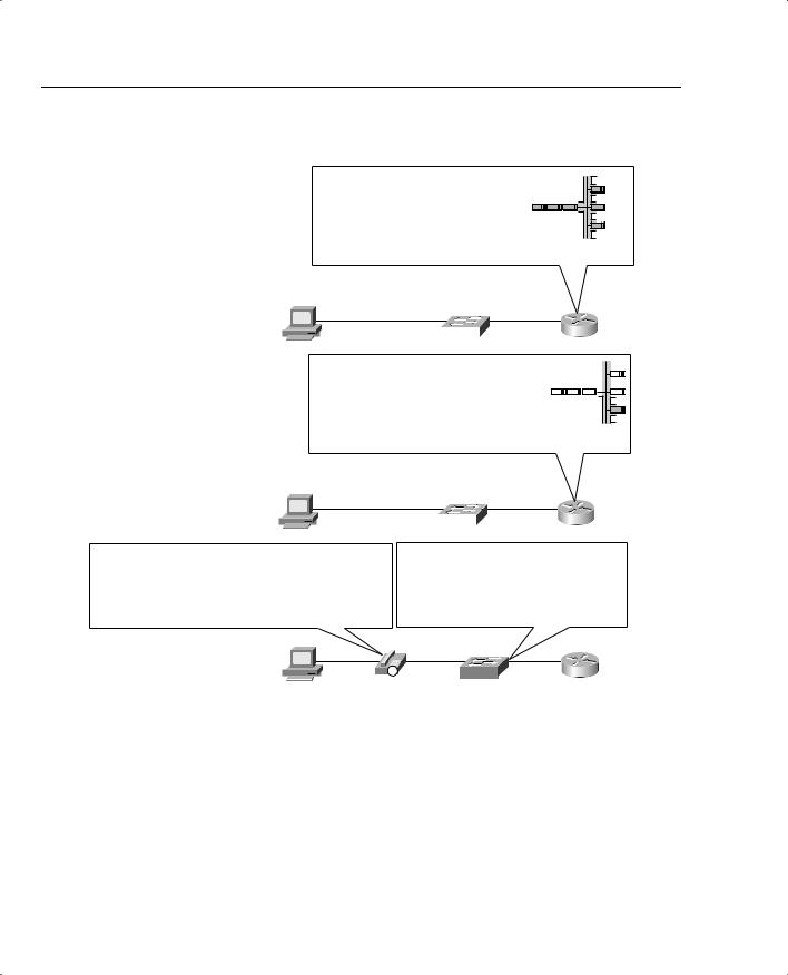
Figure 3-6 Three Classification and Marking Placement Strategies
SW1 Not Capable of Classification and Marking on Layer 3
Strategy:
Classification and Marking IP Precedence and IP DSCP on Ingress at R1
L2 QoS
SW1 |
|
|
R1 |
|
|
|
|
|
|
|
|
|
|
|
|
|
|
|
|
|
|
|
|
|
|
|
|
|
|
|
|
|
|
|
|
|
|
|
|
|
|
|
|
|
|
|
|
|
|
|
|
|
|
|
|
|
|
|
|
|
|
|
SW2 Is Capable of Classification and Marking on Layer 3
Strategy:
Classification and Marking IP Precedence and IP DSCP on Ingress at
SW2 or IP Precedence and IP DSCP on Ingress at R2
L3 QoS
SW2 |
R2 |
SW3 and IP Phone Are Capable of Classification and Marking on Layer 3 Strategy:
-IP Phone Resets CoS, IP Precedence and IP DSCP Value of PC Traffic to 0
-IP Phone Marks CoS, IP Precedence and IP DSCP Value to 5 for Its Voice Traffic
Strategy Continued:
- Classification and Marking IP Precedence and IP DSCP for Data Traffic at SW3 or R2 for Further Classification
L3 QoS
IP |
SW3 |
R3 |
|
Figure 3-7 summarizes some of the design options for where to classify and mark, showing the remote site from Figure 3-5.
Classification and Marking Concepts 173
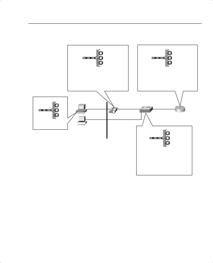
Figure 3-7 Classification and Marking Options Applied to a Typical Enterprise Network
Mark
X |
Y |
Z |
Voice Bearer Traffic Mark CoS 5, IP Precedence 5 and IP DSCP EF
Voice Signaling Traffic Mark CoS 3, IP Precedence 3 and IP DSCP AF31
Re-Mark PC Traffic CoS 0, IP Precedence 0 and IP DSCP Default
Mark
X |
Y |
Z |
If SW1 Is Layer 3 Capable:
Classification and Marking based on IP Precedence or IP DSCP for Ingress Traffic
If ISL/802.1Q to SW1:
Map Incoming CoS Value to IP Precedence or IP DSCP Values
Mark
X |
Y |
Z |
Hannah
IP |
SW1 |
R1 |
Hannah’s PC Can Mark |
|
|
|
|
|
|
|
|
|
|
|
|
|
|
|
IP Precedence and IP DSCP, |
|
|
|
|
|
|
|
and CoS if Trunking, |
Jessie |
Trust |
|||||
|
|
|
|
|
|
|
Boundary |
Mark
X |
Y |
Z |
Layer 3 Switch:
Classification and Marking Based on IP
Precedence and IP DSCP Values
Layer 2 Switch:
Classification and Marking Based on
CoS Values
The choices of where to perform classification and marking can be summarized as follows:
•Classify and mark as close to the ingress edge as possible.
•Consider the trust boundary in the network, making sure to mark or re-mark traffic after it reaches a trusted device in the network
•Because the two IP QoS marking fields—Precedence and DSCP—are carried end to end, mark one of these fields to maximize the benefits of reducing classification overhead by the other QoS tools enabled in the network.
174 Chapter 3: Classification and Marking
Typically, when the packet makes it to the first WAN router, the initial marking has occurred. However, there may be other instances where marking should take place. Consider Figure 3-8, which shows several additional options for where marking can occur.
Figure 3-8 Classification and Marking Options—Typical Enterprise WAN
Mark
X |
Y |
Z |
-Rely on Previously-Marked IP Precedence or IP DSCP Values
-May Want to Additionally Mark DE (Frame) or CLP (ATM)
To LAN
R1 |
s0 |
s0 |
R2 |
s1 |
s0 |
R3 |
Mark
X |
Y |
Z |
-Only Marked Fields that Pass PPP/HDLC Link Are IP Precedence or IP DSCP
-Rely on Previously-Marked Values
Mark
X |
Y |
Z |
-Rely on Previously-Marked IP Precedence or IP DSCP Values
-Mark LAN CoS
Most QoS tools can classify based on IP precedence and DSCP. However, the Frame Relay or ATM switches can also react to the DE and CLP bits, respectively. Therefore, you might want to set DE or CLP for the least-important traffic. If the LAN switches connected to R3 react to CoS settings, but not precedence or DSCP, which is typical of switches that only support Layer 2 QoS, you might want to mark the CoS bits on R3 before sending frames onto the Ethernet.
Finally, when you do mark CoS, IP precedence, and IP DSCP, what values should you use? Well, the “bigger is better” attitude is suggested for CoS and precedence, whereas the DiffServ PHB RFCs should be followed for DSCP settings. Cisco also suggests some specific values in cases where your policies allow for voice payload, video payload, voice/video signaling, and two classes of data. Table 3-6 lists these recommended values.