

- •QoS Overview
- •“Do I Know This Already?” Quiz
- •QoS: Tuning Bandwidth, Delay, Jitter, and Loss Questions
- •Foundation Topics
- •QoS: Tuning Bandwidth, Delay, Jitter, and Loss
- •Bandwidth
- •The clock rate Command Versus the bandwidth Command
- •QoS Tools That Affect Bandwidth
- •Delay
- •Serialization Delay
- •Propagation Delay
- •Queuing Delay
- •Forwarding Delay
- •Shaping Delay
- •Network Delay
- •Delay Summary
- •QoS Tools That Affect Delay
- •Jitter
- •QoS Tools That Affect Jitter
- •Loss
- •QoS Tools That Affect Loss
- •Summary: QoS Characteristics: Bandwidth, Delay, Jitter, and Loss
- •Voice Basics
- •Voice Bandwidth Considerations
- •Voice Delay Considerations
- •Voice Jitter Considerations
- •Voice Loss Considerations
- •Video Basics
- •Video Bandwidth Considerations
- •Video Delay Considerations
- •Video Jitter Considerations
- •Video Loss Considerations
- •Comparing Voice and Video: Summary
- •IP Data Basics
- •Data Bandwidth Considerations
- •Data Delay Considerations
- •Data Jitter Considerations
- •Data Loss Considerations
- •Comparing Voice, Video, and Data: Summary
- •Foundation Summary
- •QoS Tools and Architectures
- •“Do I Know This Already?” Quiz
- •QoS Tools Questions
- •Differentiated Services Questions
- •Integrated Services Questions
- •Foundation Topics
- •Introduction to IOS QoS Tools
- •Queuing
- •Queuing Tools
- •Shaping and Policing
- •Shaping and Policing Tools
- •Congestion Avoidance
- •Congestion-Avoidance Tools
- •Call Admission Control and RSVP
- •CAC Tools
- •Management Tools
- •Summary
- •The Good-Old Common Sense QoS Model
- •GOCS Flow-Based QoS
- •GOCS Class-Based QoS
- •The Differentiated Services QoS Model
- •DiffServ Per-Hop Behaviors
- •The Class Selector PHB and DSCP Values
- •The Assured Forwarding PHB and DSCP Values
- •The Expedited Forwarding PHB and DSCP Values
- •The Integrated Services QoS Model
- •Foundation Summary
- •“Do I Know This Already?” Quiz Questions
- •CAR, PBR, and CB Marking Questions
- •Foundation Topics
- •Marking
- •IP Header QoS Fields: Precedence and DSCP
- •LAN Class of Service (CoS)
- •Other Marking Fields
- •Summary of Marking Fields
- •Class-Based Marking (CB Marking)
- •Network-Based Application Recognition (NBAR)
- •CB Marking show Commands
- •CB Marking Summary
- •Committed Access Rate (CAR)
- •CAR Marking Summary
- •Policy-Based Routing (PBR)
- •PBR Marking Summary
- •VoIP Dial Peer
- •VoIP Dial-Peer Summary
- •Foundation Summary
- •Congestion Management
- •“Do I Know This Already?” Quiz
- •Queuing Concepts Questions
- •WFQ and IP RTP Priority Questions
- •CBWFQ and LLQ Questions
- •Comparing Queuing Options Questions
- •Foundation Topics
- •Queuing Concepts
- •Output Queues, TX Rings, and TX Queues
- •Queuing on Interfaces Versus Subinterfaces and Virtual Circuits (VCs)
- •Summary of Queuing Concepts
- •Queuing Tools
- •FIFO Queuing
- •Priority Queuing
- •Custom Queuing
- •Weighted Fair Queuing (WFQ)
- •WFQ Scheduler: The Net Effect
- •WFQ Scheduling: The Process
- •WFQ Drop Policy, Number of Queues, and Queue Lengths
- •WFQ Summary
- •Class-Based WFQ (CBWFQ)
- •CBWFQ Summary
- •Low Latency Queuing (LLQ)
- •LLQ with More Than One Priority Queue
- •IP RTP Priority
- •Summary of Queuing Tool Features
- •Foundation Summary
- •Conceptual Questions
- •Priority Queuing and Custom Queuing
- •CBWFQ, LLQ, IP RTP Priority
- •Comparing Queuing Tool Options
- •“Do I Know This Already?” Quiz
- •Shaping and Policing Concepts Questions
- •Policing with CAR and CB Policer Questions
- •Shaping with FRTS, GTS, DTS, and CB Shaping
- •Foundation Topics
- •When and Where to Use Shaping and Policing
- •How Shaping Works
- •Where to Shape: Interfaces, Subinterfaces, and VCs
- •How Policing Works
- •CAR Internals
- •CB Policing Internals
- •Policing, but Not Discarding
- •Foundation Summary
- •Shaping and Policing Concepts
- •“Do I Know This Already?” Quiz
- •Congestion-Avoidance Concepts and RED Questions
- •WRED Questions
- •FRED Questions
- •Foundation Topics
- •TCP and UDP Reactions to Packet Loss
- •Tail Drop, Global Synchronization, and TCP Starvation
- •Random Early Detection (RED)
- •Weighted RED (WRED)
- •How WRED Weights Packets
- •WRED and Queuing
- •WRED Summary
- •Flow-Based WRED (FRED)
- •Foundation Summary
- •Congestion-Avoidance Concepts and Random Early Detection (RED)
- •Weighted RED (WRED)
- •Flow-Based WRED (FRED)
- •“Do I Know This Already?” Quiz
- •Compression Questions
- •Link Fragmentation and Interleave Questions
- •Foundation Topics
- •Payload and Header Compression
- •Payload Compression
- •Header Compression
- •Link Fragmentation and Interleaving
- •Multilink PPP LFI
- •Maximum Serialization Delay and Optimum Fragment Sizes
- •Frame Relay LFI Using FRF.12
- •Choosing Fragment Sizes for Frame Relay
- •Fragmentation with More Than One VC on a Single Access Link
- •FRF.11-C and FRF.12 Comparison
- •Foundation Summary
- •Compression Tools
- •LFI Tools
- •“Do I Know This Already?” Quiz
- •Foundation Topics
- •Call Admission Control Overview
- •Call Rerouting Alternatives
- •Bandwidth Engineering
- •CAC Mechanisms
- •CAC Mechanism Evaluation Criteria
- •Local Voice CAC
- •Physical DS0 Limitation
- •Max-Connections
- •Voice over Frame Relay—Voice Bandwidth
- •Trunk Conditioning
- •Local Voice Busyout
- •Measurement-Based Voice CAC
- •Service Assurance Agents
- •SAA Probes Versus Pings
- •SAA Service
- •Calculated Planning Impairment Factor
- •Advanced Voice Busyout
- •PSTN Fallback
- •SAA Probes Used for PSTN Fallback
- •IP Destination Caching
- •SAA Probe Format
- •PSTN Fallback Scalability
- •PSTN Fallback Summary
- •Resource-Based CAC
- •Resource Availability Indication
- •Gateway Calculation of Resources
- •RAI in Service Provider Networks
- •RAI in Enterprise Networks
- •RAI Operation
- •RAI Platform Support
- •Cisco CallManager Resource-Based CAC
- •Location-Based CAC Operation
- •Locations and Regions
- •Calculation of Resources
- •Automatic Alternate Routing
- •Location-Based CAC Summary
- •Gatekeeper Zone Bandwidth
- •Gatekeeper Zone Bandwidth Operation
- •Single-Zone Topology
- •Multizone Topology
- •Zone-per-Gateway Design
- •Gatekeeper in CallManager Networks
- •Zone Bandwidth Calculation
- •Gatekeeper Zone Bandwidth Summary
- •Integrated Services / Resource Reservation Protocol
- •RSVP Levels of Service
- •RSVP Operation
- •RSVP/H.323 Synchronization
- •Bandwidth per Codec
- •Subnet Bandwidth Management
- •Monitoring and Troubleshooting RSVP
- •RSVP CAC Summary
- •Foundation Summary
- •Call Admission Control Concepts
- •Local-Based CAC
- •Measurement-Based CAC
- •Resources-Based CAC
- •“Do I Know This Already?” Quiz
- •QoS Management Tools Questions
- •QoS Design Questions
- •Foundation Topics
- •QoS Management Tools
- •QoS Device Manager
- •QoS Policy Manager
- •Service Assurance Agent
- •Internetwork Performance Monitor
- •Service Management Solution
- •QoS Management Tool Summary
- •QoS Design for the Cisco QoS Exams
- •Four-Step QoS Design Process
- •Step 1: Determine Customer Priorities/QoS Policy
- •Step 2: Characterize the Network
- •Step 3: Implement the Policy
- •Step 4: Monitor the Network
- •QoS Design Guidelines for Voice and Video
- •Voice and Video: Bandwidth, Delay, Jitter, and Loss Requirements
- •Voice and Video QoS Design Recommendations
- •Foundation Summary
- •QoS Management
- •QoS Design
- •“Do I Know This Already?” Quiz
- •Foundation Topics
- •The Need for QoS on the LAN
- •Layer 2 Queues
- •Drop Thresholds
- •Trust Boundries
- •Cisco Catalyst Switch QoS Features
- •Catalyst 6500 QoS Features
- •Supervisor and Switching Engine
- •Policy Feature Card
- •Ethernet Interfaces
- •QoS Flow on the Catalyst 6500
- •Ingress Queue Scheduling
- •Layer 2 Switching Engine QoS Frame Flow
- •Layer 3 Switching Engine QoS Packet Flow
- •Egress Queue Scheduling
- •Catalyst 6500 QoS Summary
- •Cisco Catalyst 4500/4000 QoS Features
- •Supervisor Engine I and II
- •Supervisor Engine III and IV
- •Cisco Catalyst 3550 QoS Features
- •Cisco Catalyst 3524 QoS Features
- •CoS-to-Egress Queue Mapping for the Catalyst OS Switch
- •Layer-2-to-Layer 3 Mapping
- •Connecting a Catalyst OS Switch to WAN Segments
- •Displaying QoS Settings for the Catalyst OS Switch
- •Enabling QoS for the Catalyst IOS Switch
- •Enabling Priority Queuing for the Catalyst IOS Switch
- •CoS-to-Egress Queue Mapping for the Catalyst IOS Switch
- •Layer 2-to-Layer 3 Mapping
- •Connecting a Catalyst IOS Switch to Distribution Switches or WAN Segments
- •Displaying QoS Settings for the Catalyst IOS Switch
- •Foundation Summary
- •LAN QoS Concepts
- •Catalyst 6500 Series of Switches
- •Catalyst 4500/4000 Series of Switches
- •Catalyst 3550/3524 Series of Switches
- •QoS: Tuning Bandwidth, Delay, Jitter, and Loss
- •QoS Tools
- •Differentiated Services
- •Integrated Services
- •CAR, PBR, and CB Marking
- •Queuing Concepts
- •WFQ and IP RTP Priority
- •CBWFQ and LLQ
- •Comparing Queuing Options
- •Conceptual Questions
- •Priority Queuing and Custom Queuing
- •CBWFQ, LLQ, IP RTP Priority
- •Comparing Queuing Tool Options
- •Shaping and Policing Concepts
- •Policing with CAR and CB Policer
- •Shaping with FRTS, GTS, DTS, and CB Shaping
- •Shaping and Policing Concepts
- •Congestion-Avoidance Concepts and RED
- •WRED
- •FRED
- •Congestion-Avoidance Concepts and Random Early Detection (RED)
- •Weighted RED (WRED)
- •Flow-Based WRED (FRED)
- •Compression
- •Link Fragmentation and Interleave
- •Compression Tools
- •LFI Tools
- •Call Admission Control Concepts
- •Local-Based CAC
- •Measurement-Based CAC
- •Resources-Based CAC
- •QoS Management Tools
- •QoS Design
- •QoS Management
- •QoS Design
- •LAN QoS Concepts
- •Catalyst 6500 Series of Switches
- •Catalyst 4500/4000 Series of Switches
- •Catalyst 3550/3524 Series of Switches
- •Foundation Topics
- •QPPB Route Marking: Step 1
- •QPPB Per-Packet Marking: Step 2
- •QPPB: The Hidden Details
- •QPPB Summary
- •Flow-Based dWFQ
- •ToS-Based dWFQ
- •Distributed QoS Group–Based WFQ
- •Summary: dWFQ Options

710 Chapter 10: LAN QoS
Layer 3 Switching Engine QoS Packet Flow
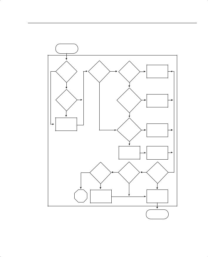
The PFC has the capability to classify, mark, and police traffic based on both Layer 2 and Layer 3 elements. The PFC also introduces the concept of QoS ACLs, which can be used for granular control over QoS configurations. Figure 10-9 illustrates the flow of a frame or packet through a PFC.
As the packet arrives at the PFC, the ingress interface or the ingress VLAN is examined to see whether an ACL is applied. If an ACL is not applied to either the ingress port or the ingress VLAN, the packet uses the default ACL. The default IP ACL consists of a single ACE that has a configurable marking rule and configurable policing rules. If the default ACL has not been configured, the ACE in the default ACL applies a DSCP value of 0 to all traffic passed from ingress ports configured with the untrusted port keyword. If an ACL is applied to the port or VLAN, the ACL examines the ACEs to see whether any entries match the arriving packet.
The PFC uses a DSCP setting for each IP packet that it processes. The PFC asks itself, “Do we trust the DSCP, IP precedence, or CoS values on the frame?” If these values are not trusted, the DSCP value specified in the default ACL is used. If these values are trusted, the switch uses the DSCP values received. For IP precedence and CoS values, the PFC uses an internal DSCP value generated from the IP precedence-to-DSCP or the CoS-to-DSCP mappings, respectively.
If policing has been enabled, the PFC determines the current traffic rate and decides to drop the packet, re-mark the packet, or place the packet in the egress queue unchanged.
If the packet is destined for the egress queue, the CoS value is derived from the DSCP value before the packet is delivered.
Egress Queue Scheduling
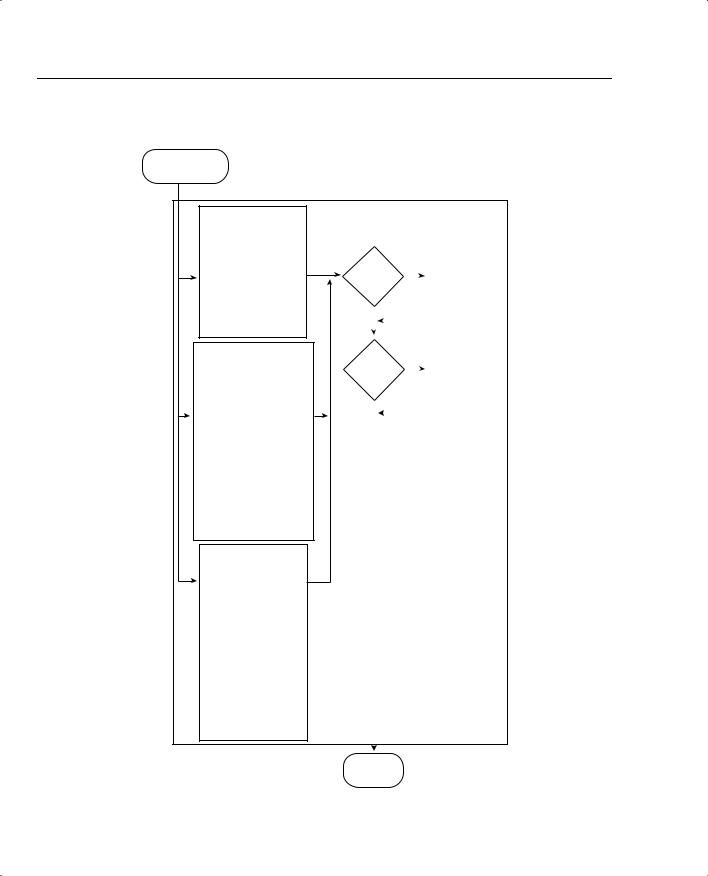
Egress queue scheduling defines the treatment that a frame or packet receives as it exits the switch. Figure 10-10 shows the treatment received by the frame or packet in the egress queue.
As the frame arrives at the egress queue, the CoS value is examined to determine the proper queue and threshold for the egress interface type. In this example, the switch has three different queues that a frame can be placed in: 2q2t, 1p2q2t, and 1p3q1t. The CoS value determines the proper egress queue. After the proper queue and threshold has been identified, the question is asked “Is there room in the egress queue for this frame or has the drop threshold for this CoS value been met?” If the threshold has been met, the frame is dropped; otherwise the frame is placed in a queue to await transport.
Cisco Catalyst Switch QoS Features 711
Figure 10-9 Layer 3 Switching Engine Classification, Marking, and Policing
From Ingress
Port or VLAN
|
|
L3 Switching Engine (PFC) Classification, Marking, and Policing |
|||||
No |
ACL(s) |
|
IP |
Yes |
1Trust |
Yes |
Use Received |
on |
|
Received |
|||||
|
|
Packet? |
|
|
DSCP |
||
|
Interface? |
|
|
DSCP? |
|
||
|
|
|
|
|
|
||
|
Yes |
|
No |
|
No |
|
|
|
|
|
|
|
|
||
|
Match |
Yes |
|
|
1Trust |
Yes |
2Set DSCP |
|
|
|
Received IP |
||||
|
ACE in ACL? |
|
|
|
Precedence? |
|
from Received |
|
|
|
|
|
|
IP Precedence |
|
|
|
|
|
|
|
|
|
|
No |
|
|
|
No |
|
|
|
Use Default |
|
|
|
1Trust |
|
|
|
ACL |
|
|
|
Yes |
3Set DSCP |
|
|
|
|
|
|
Received or |
from Received |
|
|
|
|
|
|
Port CoS? |
|
|
|
|
|
|
|
|
or Port CoS |
|
|
|
|
|
|
|
|
|
|
|
|
|
|
No |
|
|
|
|
|
|
|
1Trust Is from |
|
Use DSCP |
|
|
|
|
|
an Untrusted |
|
from |
|
|
|
|
|
Port |
|
ACE |
|
|
No |
Markdown? |
Yes |
Out of |
Yes |
Policing |
|
|
|
|
Profile? |
|
Rule in |
|
|
|
|
|
|
|
ACE? |
|
|
|
|
|
|
|
|
|
|
|
|
Yes |
|
No |
|
No |
|
|
Drop |
4Set DSCP |
|
|
|
5Derive CoS |
|
|
Packet |
to Marked |
|
|
|
from DSCP |
|
|
|
Down Value |
|
|
|
|
1Specified by ACE Keyword or by
Port Keyword and dscp ACE Keyword To Egress Interface
2From IP Precedence-to-DSCP Map
3From CoS-to-DSCP Map
4From DSCP Markdown Map
5From DSCP-to-CoS Map
712 Chapter 10: LAN QoS
Figure 10-10 Ethernet Egress Port Treatment
From Switching
Engine or MSFC
Ethernet Egress port Scheduling, Congestion Avoidance, and Marking
2q2t Port (tail-drop thresholds)
High Priority
Standard Queue 100% for CoS 6 and 7 80% for CoS 4 and 5
Low Priority
Standard Queue 100% for CoS 2 and 3 80% for CoS 0 and 1
1p2q2t Port
Strict Priority Queue
100% for CoS 5
High Priority
Standard Queue (WRED-drop thresholds)
70%:100% for CoS 6 and 7 40%:70% for CoS 4
Low Priority
Standard Queue (WRED-drop thresholds)
70%:100% for CoS 2 and 3 40%:70% for CoS 0 and 1
1p3q1t Port
Strict Priority Queue
100% for CoS 5
Standard Queues (WRED-drop or tail-drop thresholds)
High Priority 100% for CoS 6 and 7
Medium Priority 100% for CoS 2, 3 and 4
Low Priority 100% for CoS 0 and 1
IP Traffic Yes |
Write ToS |
|||||||||
from PFC? |
|
|
|
Byte into |
||||||
|
|
|
||||||||
|
|
|
Packet |
|||||||
|
|
|
|
|
|
|
|
|
||
No |
|
|
|
|
|
|
|
|
|
|
|
|
|
|
|
|
|
|
|
|
|
|
|
|
|
|
|
|
||||
|
|
|
|
|
|
|
|
|
|
|
|
|
|
|
|
|
|
|
|
|
|
|
|
|
|
|
|
|
|
|
|
|
ISL or |
Yes |
Write CoS |
||||||||
|
|
|
into |
|||||||
802.1q? |
|
|
|
|||||||
|
|
|
Frame |
|||||||
|
|
|
|
|
|
|
|
|
||
No |
|
|
|
|
|
|
|
|
|
|
|
|
|
|
|
|
|
||||
|
|
|
|
|
|
|||||
|
|
|
|
|
|
|
|
|
|
|
|
|
|
|
|
|
|
|
|
|
|
(Default Values Shown)
Transmit
Frame