Добавил:
Опубликованный материал нарушает ваши авторские права? Сообщите нам.
Вуз: Предмет: Файл:
DQOS Exam Certification Guide - Cisco press.pdf
Скачиваний:
69
Добавлен:
24.05.2014
Размер:
12.7 Mб
Скачать

690 Chapter 10: LAN QoS

Foundation Topics

The Need for QoS on the LAN

LAN quality of service (QoS) is often misunderstood and overlooked. Thanks to conventional wisdom, most network administrators think that they do not require LAN QoS. If your plans include the addition of real-time applications, such as IP telephony or video conferencing, you should include a strategy for LAN QoS while you are in the planning stages of your project. This up-front planning can result in the perceived success or failure of your project in the eyes of the end users.

This chapter explores the need for LAN QoS and discusses the following options available to you:

Layer 2 priority (CoS)

Layer 3-to-Layer 2 (DSCP-to-CoS) mapping

Layer 2 queues

Drop thresholds

Trust boundaries

Cisco switch configurations for LAN QoS

Buffer Overflow (Overrun)

Suppose that is it 8:30 on a Monday morning. All of your fellow employees report to work, simultaneously power on their computers, and begin their day. Their traffic flows through the access layer switches and converge on the uplink port to the distribution layer switch. In the event that the uplink port is smaller than the input port, or the uplink port is oversubscribed, the buffer on the uplink port begins to fill, as shown in Figure 10-1.

Figure 10-1 Buffer Overflow


Buffer Full —


Packets Dropped


Current Traffic Load = 350 Mbps


1 Gigabit Port


100 Megabit Port


Buffer Full —


Packets Dropped

Aggregate Traffic Load = 250 Mbps


100 Megabit Ports


100 Megabit Port

The Need for QoS on the LAN 691

For an instant, the buffer of the uplink port can become full, potentially causing packets to drop. In a typical TCP/IP data-networking environment, this is not a concern because the packet is retransmitted. In an environment comprised of real-time applications, such as IP telephony and video conferencing, instantaneous buffer overruns (overflows) can affect the quality of the voice or video streams.

In a Cisco IP telephony environment, a G.729 digital signal processor (DSP) can rebuild up to 30 ms of lost voice. If the Cisco standard 20 ms per packet has been deployed, a single packet can be dropped without degrading voice quality; if two consecutive voice packets are lost, resulting in 40 ms of lost voice conversation, however, the algorithm cannot compensate, and a clip is heard in the conversation. In the event that the Real Time Protocol (RTP) stream carries a fax or modem conversation, a single packet results in a modem retrain, whereas two consecutive packets result in a dropped connection.

By classifying the real-time applications on your LAN and scheduling the desired level of priority for each real-time application, you can avoid these problems; however, you cannot remedy the problem by adding bandwidth. QoS tools are required to manage these buffers to minimize loss, delay, and jitter. You must properly enable and configure QoS to set priority by matching a traffic flow with a desired queue or threshold.

Bandwidth is not a substitute for LAN QoS! LAN QoS is a buffer management issue.

Marking and Classification

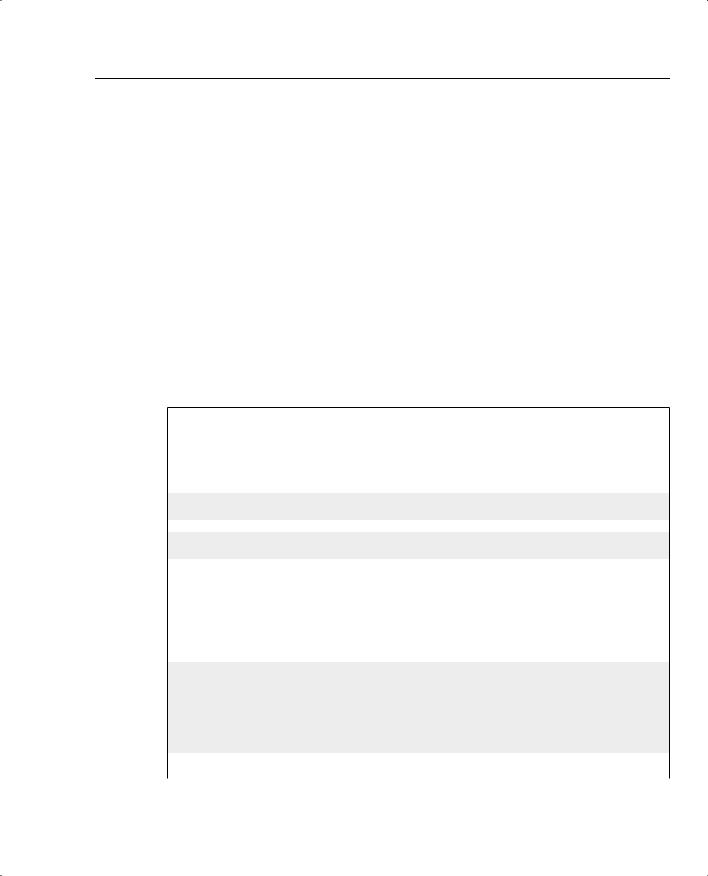
As discussed in Chapter 3, “Classification and Marking,” marking at Layer 2 takes place in the 3-bit User Priority field called the Class of Service (CoS), which resides inside an Ethernet header. The CoS field only exists inside Ethernet frames when trunking (either 802.1Q or InterSwitch Link [ISL]) is used. The field can be used to set eight different binary values, which the classification features of other QoS tools can use.

Figure 10-2 shows the general location of the CoS field inside the 802.1q and ISL headers.

As discussed in Chapter 3, Layer 3 marking takes place in the Type of Service (ToS) or Differentiated Services (DS) field in the IP Header. The IP Precedence and Differentiated Services Code Point (DSCP) fields can be marked with any valid binary value of either 3 or 6 bits, respectively. Chapter 2, “QoS Tools and Architectures,” contains detailed discussion of the recommended values used in these two fields. Figure 10-3 outlines the two fields and their positions inside an IP header.

692 Chapter 10: LAN QoS

Figure 10-2 Class of Service Fields

ISL User Field (1 byte)

Frame Type


CoS


ISL Header

ISL Header


Original Frame


(26 Bytes)


802.1q/P


Dest.


Src


Ether


Tag


Header


Type


User


VLAN ID


Priority


802.1q Tag Field (2 bytes)

Figure 10-3 IP Precedence and IP DSCP Fields

Precedence TOS CU

IP Header,

Byte 1

TOS Byte

Bytes 3-20

Before DiffServ


IP Header,


Byte 1

DS Field*

Bytes 3-20

After DiffServ


DSCP CU

The Need for QoS on the LAN 693

Layer 3-to-Layer 2 Classification Mapping

Layer 2 switches perform QoS features based on the CoS field within the Ethernet headers without regard for the markings within the IP header. As discussed in Chapter 3, when a packet exits a router interface that is not configured as an 802.1Q trunk, a CoS value does not exist. The receiving switch marks the packet with the default CoS value configured on the receiving port, typically 0, although the DSCP value may be expedited forwarding (EF). If the switch receiving the packet cannot classify on DSCP markings, this packet is classified as a best-effort packet, even if the intent was to provide prioritization.

To solve this problem, you must map the Layer 3 marking to Layer 2 marking on the router, and perform trunking between the switch and the router, so that the Layer 2 switch can properly classify the received traffic. Without remapping, L2 switches cannot differentiate between traffic flows.

Example 10-1 shows the configuration necessary to map IP DSCP to CoS that enables the Layer 2 switch to prioritize traffic. This example also shows a CoS-to-IP DSCP map that allows the router to match incoming CoS values with DSCP values.

Example 10-1 DSCP-to-CoS Mapping

class-map cos3 match cos 3

!

class-map cos5 match cos 5

!

class-map EF match ip dscp EF

!

class-map AF31 match ip dscp AF31

policy-map map-cos-to-dscp class cos5

set ip DSCP EF class cos3

set ip dscp af31 class class-default set ip dscp default

!

policy-map map-dscp-to-cos class EF

set cos 5 class AF31 set cos 3

class class-default set cos 0

!

interface FastEthernet0/0

continues