Добавил:
Опубликованный материал нарушает ваши авторские права? Сообщите нам.
Вуз: Предмет: Файл:
DQOS Exam Certification Guide - Cisco press.pdf
Скачиваний:
69
Добавлен:
24.05.2014
Размер:
12.7 Mб
Скачать

482 Chapter 7: Link-Efficiency Tools

Foundation Topics

Payload and Header Compression

Compression involves mathematical algorithms that encode the original packet into a smaller string of bytes. After sending the smaller encoded string to the other end of a link, the compression algorithm on the other end of the link reverses the process, reverting the packet back to its original state.

Over the years, many mathematicians and computer scientists have developed new compression algorithms that behave better or worse under particular conditions. For instance, each algorithm takes some amount of computation, some memory, and they result in saving some number

of bytes of data. In fact, you can compare compression algorithms by calculating the ratio of original number of bytes, divided by the compressed number of bytes—a value called the compression ratio. Depending on what is being compressed, the different compression algorithms have varying success with their compression ratios, and each uses different amounts of CPU and memory.

In Cisco routers, compression tools can be divided into two main categories: payload compression and header compression. Payload compression compresses headers and the user data, whereas header compression only compresses headers. As you might guess, payload compression can provide a larger compression ratio for larger packets with lots of user data in them, as compared to header compression tools. Conversely, header compression tools work well when the packets tend to be small, because headers comprise a large percentage of the packet. Figure 7-1 shows the fields compressed by payload compression, and by both types of header compression. (Note that the abbreviation DL stands for data link, representing the data-link header and trailer.)

Figure 7-1 Payload and Header Compression

Payload Compression

DL IP TCP

Data

DL

TCP Header Compression

RTP Header Compression

DL IP UDP RTP Data DL

Payload and Header Compression 483

Both types of compression tools require CPU cycles and memory. Payload compression algorithms tend to take a little more computation and memory, just based on the fact that they have more bytes to process, as seen in Figure 7-1. With any of the compression tools, however, the computation time required to perform the compression algorithm certainly adds delay to the packet. The bandwidth gained by compression must be more important to you than the delay added by compression processing, otherwise you should choose not to use compression at all!

Figure 7-2 outlines an example showing the delays affected by compression. The compression and decompression algorithms take time, of course. However, serialization delay decreases, because the packets are now smaller. Queuing delay also decreases. In addition, on Frame Relay and ATM networks, the network delay decreases, because the network delay is affected by the amount of bits sent into the network.

Figure 7-2 Delay Versus Bandwidth with Compression

Without Compression

Client1

Forwarding Delay:

Network Delay:

Forwarding Delay:


1 ms

40 ms

1 ms

Total Delay: 57 ms

Server 1

SW1

R1

R3

SW2

192.168.1.100

Serialization Delay: 15 ms

With Compression

Client1

Forwarding Delay:

Network Delay:

Forwarding Delay:


(Including Compression):

30 ms

Including Decompression):

Total Delay: 57 ms

10 ms


10 ms


Server 1


SW1

R1

R3

SW2

192.168.1.100

Serialization Delay: 7 ms

This example uses contrived numbers to make the relevant points. The example assumes a 2:1 compression ratio, with a 1500-byte packet, and 768-kbps access links on both ends. The various delay components in the top half of the figure, without compression, add up to 57 ms. In the lower figure, with compression, the delay is still 57 ms. Because a 2:1 compression ratio was achieved, twice as much traffic can be sent without adding delay—it seems like an obvious choice to use compression! However, compression uses CPU and memory, and it is difficult to predict how compression will work on a particular router in a particular network. Compression requires that you try it, monitor CPU utilization, look at the compression ratios, and experiment before just deciding to add it to all routers over an entire network. In addition, although this

484 Chapter 7: Link-Efficiency Tools

example shows no increase in delay, in most cases, just turning on software compression will probably increase delay slightly, but still with the benefit of increasing the amount of traffic you can send over the link.

Compression hardware minimizes the delay added by compression algorithms. Cisco offers several types of hardware compression cards that reduce the delay taken to compress the packets. Cisco offers compression service adapters on 7200, 7300, 7400, 7500 routers, compression advanced integration modules (AIMs) on 3660 and 2600 routers, and compression network modules for 3620s and 3640s. On 7500s with Versatile Interface Processors (VIPs), the compression work can be distributed to the VIP cards, even if no compression adapters are installed. Thankfully, when the compression cards are installed, IOS assumes that you want the compression to occur on the card by default, requiring you to specifically configure software compression if you do not want to use the compression hardware for some reason.

Payload Compression

Cisco IOS Software supplies three different options for point-to-point payload compression tools on serial links, namely Stacker, Microsoft Point-to-Point Compression (MPPC), and Predictor. Consider the following criteria when choosing between the payload compression options:

The types of data-link protocols supported

The efficiency of the compression algorithm used

Whether the device on the other end of the link supports the tool

Of course, when two Cisco routers are used on each end, compatibility is not an issue, although Cisco does recommend that you use the same IOS revision on each end of the link when using compression.

Stacker and MPPC both use the same Lempel-Ziv compression algorithm. Predictor compression is named after the compression algorithm it uses. Predictor tends to take slightly less CPU and memory than does Lempel-Ziv, but Lempel-Ziv typically produces a better compression ratio.

The final factor on which tools to use is whether the tool supports the data-link protocol you are using. Of the three options, Stacker supports more data-link protocols than the other two tools. Table 7-2 outlines the main points of comparison for the three payload compression tools.

Table 7-2

Point-to-Point Payload Compression Tools: Feature Comparison


Feature

Stacker

MPPC

Predictor


Uses Lempel-Ziv (LZ) compression algorithm

Yes

Yes

No


Uses Predictor public domain compression algorithm

No

No

Yes


Supported on High-Level Data Link Control (HDLC)

Yes

No

No


Payload and Header Compression 485

Table 7-2

Point-to-Point Payload Compression Tools: Feature Comparison (Continued)


Feature

Stacker

MPPC

Predictor


Supported on X.25

Yes

No

No


Supported on Link Access Procedure, Balanced (LAPB)

Yes

No

Yes


Supported on Frame Relay

Yes

No

No


Supported on Point-to-Point Protocol (PPP)

Yes

Yes

Yes


Supported on ATM (using multilink PPP)

Yes

Yes

Yes


Cisco IOS Software supplies three different options for payload compression on Frame Relay VCs as well. Cisco IOS Software includes two proprietary options, called packet-by-packet and data stream, and one compression technique based on Frame Relay Forum Implementation Agreement 9 (FRF.9). FRF.9 compression and data-stream compression function basically the same, with the only real difference being that FRF.9 implies compatibility with non-Cisco devices. Both data stream and FRF.9 compression use the Stacker algorithm (which is based on the Lempel-Ziv algorithm), with the dictionary created by Stacker being built and expanded for all packets on a VC. (Lempel-Ziv works by defining small strings of bytes inside the original packet, assigning these strings a short binary code, sending the short binary code rather than the longer original. The table of short binary codes, and their longer associated string of bytes, is called a dictionary.) The packet-by-packet compression method also uses Stacker, but the compression dictionary built for each packet is discarded—hence the name packet-by-packet compression. Table 7-3 lists the three tools and their most important distinguishing features.

Table 7-3 Frame Relay Payload Compression Tools: Feature Comparison

Feature

Packet-by-Packet

FRF.9

Data Stream


Uses Stacker compression algorithm

Yes

Yes

Yes


Builds compression dictionary over time for all

No

Yes

Yes

packets on a VC, not just per packet


Cisco proprietary

Yes

No

Yes


Header Compression

Header compression algorithms take advantage of the fact that the headers are predictable. If you capture the frames sent across a link with a network analyzer, for instance, and look at IP packets from the same flow, you see that the IP headers do not change a lot, nor do the TCP headers, or UDP and RTP headers if RTP is used. Therefore, header compression can significantly reduce the size of the headers with a relatively small amount of computation. In fact, TCP header compression compresses the IP and TCP header (originally 40 bytes combined) down to between 3 and 5 bytes. Similarly, RTP header compression compresses the IP, UDP, and

486 Chapter 7: Link-Efficiency Tools

RTP headers (originally 40 bytes combined) to 2 to 4 bytes. The variation in byte size for RTP headers results from the presence of a UDP checksum. Without the checksum, the RTP header is 2 bytes; with the checksum, the RTP header is 4 bytes.

TCP header compression results in large compression ratios if the TCP packets are relatively small. If the packets have a minimum length (64 bytes), with 40 of those being the IP and TCP headers, the compressed packet is between 27 and 29 bytes! That gives a compression ratio of 64/27, or about 2.37, which is pretty good for a compression algorithm that uses relatively little CPU. However, a 1500-byte packet with TCP header compression saves 35 to 37 bytes of the original 1500-byte packet, providing a compression ratio of 1500/1497, or about 1.002, a relatively insignificant savings in this case.

RTP header compression typically provides a good compression result for voice traffic, because VoIP tends always to use small packets. For instance, G.729 codecs in Cisco routers uses 20 bytes of data, preceded by 40 bytes of IP, UDP, and RTP headers. After compression, the headers are down to 4 bytes, and the packet size falls from 60 bytes to 24 bytes! Table 7-4 lists some of the overall VoIP bandwidth requirements, and the results of RTP header compression.

Table 7-4 Bandwidth Requirements for Various Types of Voice Calls With and Without cRTP


Payload

IP/UDP/RTP

Layer 2

Layer 2

Total

Codec

Bandwidth

Header size

header Type

header Size

Bandwidth


G.711

64 kbps

40 bytes

Ethernet

14

85.6


G.711

64 kbps

40 bytes

MLPPP/FR

6

82.4


G.711

64 kbps

2 bytes (cRTP)

MLPPP/FR

6

67.2


G.729

8 kbps

40 bytes

Ethernet

14

29.6


G.729

8 kbps

40 bytes

MLPPP/FR

6

26.4


G.729

8 kbps

2 bytes (cRTP)

MLPPP/FR

6

11.2


*For DQOS test takers: These numbers are extracted from the DQOS course, so you can study these numbers. Note, however, that the numbers in the table do not include the Layer 2 trailer overhead.

Payload Compression Configuration

Payload compression requires little configuration. You must enable compression on both ends of a point-to-point serial link, or on both ends of a Frame Relay VC for Frame Relay. The compress command enables compression on point-to-point links, with the frame-relay payload-compression command enabling compression over Frame Relay.

Payload and Header Compression 487

Table 7-5 lists the various configuration and show commands used with payload compression, followed by example configurations.

Table 7-5 Configuration Command Reference for Payload Compression

Command

Mode and Function


compress predictor

Interface configuration mode; enables Predictor


compression on one end of the link.


compress stac

Interface configuration mode; enables Stacker


compression on one end of the link.


compress mppc [ignore-pfc]

Interface configuration mode; enables MPPC


compression on one end of the link.


compress stac [distributed | software]

Interface configuration mode; on 7500s with VIPs,


allows specification of whether the compression


algorithm is executed in software on the VIP.


compress {predictor | stac [csa slot |

Interface configuration mode; On 7200s, allows

software]}

specification of Predictor or Stacker compression on


a compression service adapter (CSA).


compress stac caim element-number

Interface configuration mode; enables Stacker


compression using the specified compression AIM.


frame-relay payload-compress {packet-

Interface configuration mode; enables FRF.9 or

by-packet | frf9 stac [hardware-options] | data-

data-stream style compression on one end of a

stream stac [hardware-options]}

Frame Relay link. Hardware-options field includes


the following options: software, distributed (for use


w/VIPs), and CSA (7200s only).


You can use the show compress command to verify that compression has been enabled on the interface and to display statistics about the compression behavior.

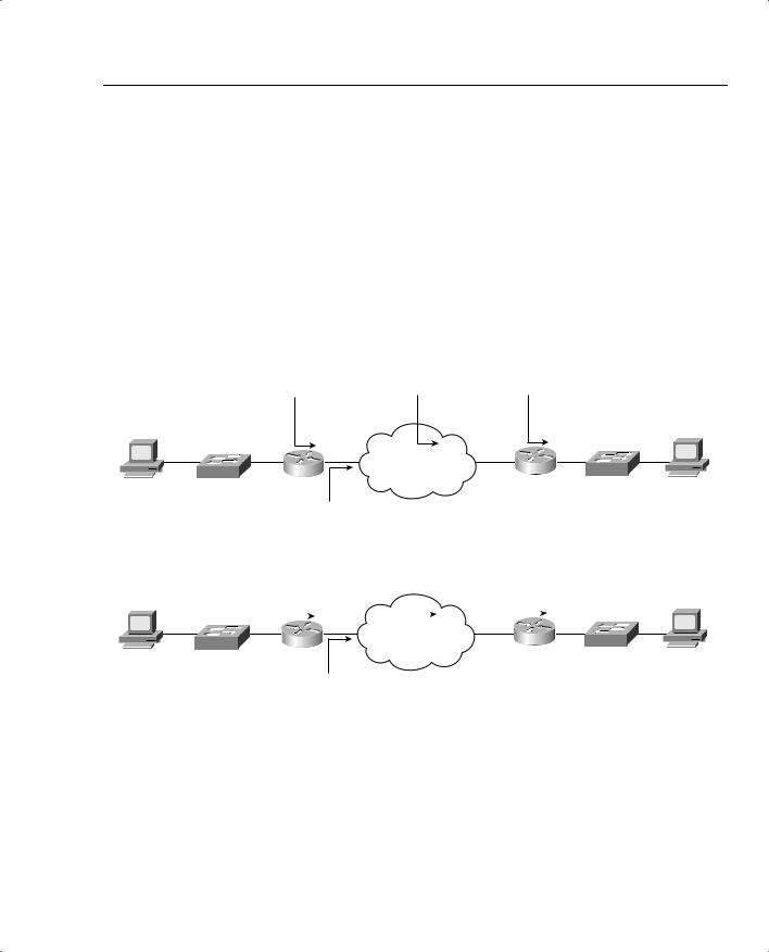
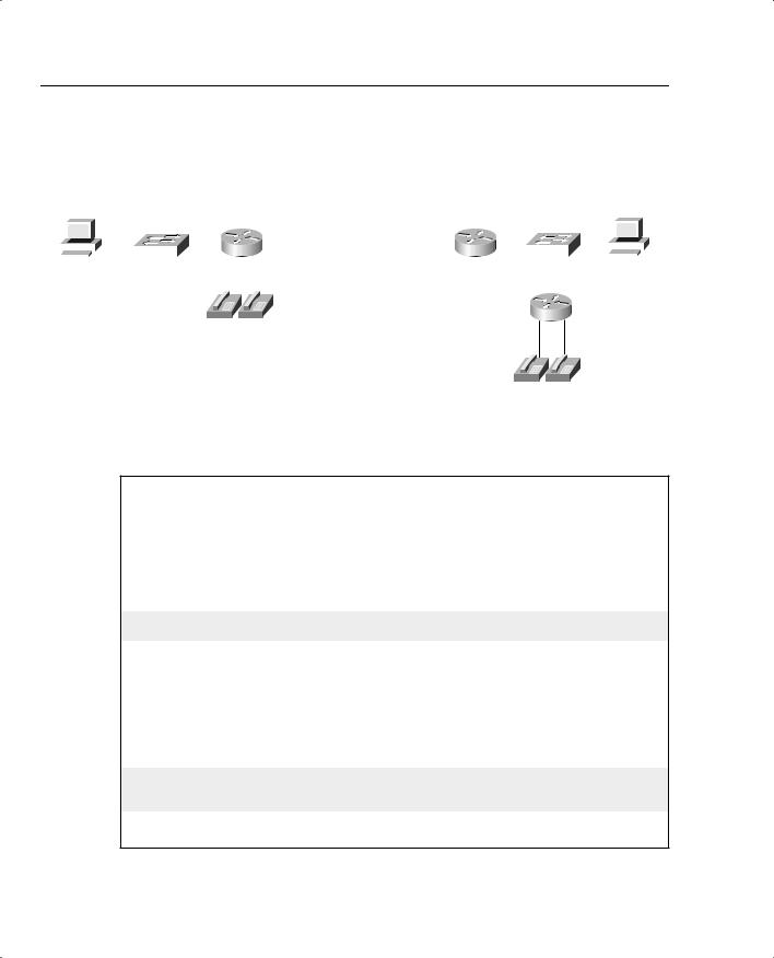
The first example uses the network described in Figure 7-3, with a PPP link between R1 and R3. The example uses the same familiar web browsing sessions, each of which downloads two JPGs. An FTP get transfers a file from the server to the client, and two voice calls between R1 and R4 are used.

488 Chapter 7: Link-Efficiency Tools

Figure 7-3 The Network Used in PPP Payload Compression Examples

Note: All IP Addresses Begin 192.168.

Client1


Server1


12.251

12.253


1.251


SW1


R1


s0/1

s0/1 R3

SW2


11.100


3.100


3.254


R4

1001 1002

3001 3002

Example 7-1 shows the Stacker compression between R1 and R3.

Example 7-1 Stacker Payload Compression Between R1 and R3 (Output from R3)

R3#show running-config

Building configuration...

!

!Lines omitted for brevity

interface Serial0/1 bandwidth 128

ip address 192.168.12.253 255.255.255.0 encapsulation ppp

compress stacker clockrate 128000

!Portions omitted for brevity

!

r3#show compress

Serial0/1

Software compression enabled uncompressed bytes xmt/rcv 323994/5494 compressed bytes xmt/rcv 0/0

1 min avg ratio xmt/rcv 1.023/1.422

5 min avg ratio xmt/rcv 1.023/1.422

10 min avg ratio xmt/rcv 1.023/1.422 no bufs xmt 0 no bufs rcv 0

resyncs 2

Payload and Header Compression 489

The configuration requires only one interface subcommand, compress stacker. You must enter this command on both ends of the serial link before compression will work. The show compress command lists statistics about how well compression is working. For instance, the 1-, 5-, and 10-minute compression ratios for both transmitted and received traffic are listed, which gives you a good idea of how much less bandwidth is being used because of compression.

You can easily configure the other two payload compression tools. Instead of the compress stacker command as in Example 7-1, just use the compress mppc or compress predictor command.

Example 7-2 shows FRF.9 payload compression. The configuration uses a point-to-point subinterface and the familiar network used on most of the other configuration examples in the book, as shown in Figure 7-4.

Figure 7-4 The Network Used in FRF.9 Payload Compression Example

Note: All IP Addresses Begin 192.168.

Client1


Server1


2.252


1.252


SW1

R1


s0/0

s0/0 R3

SW2


1.100


3.100


3.254


R4

1001 1002

3001 3002

Example 7-2 FRF.9 Payload Compression Between R1 and R3 (Output from R3)

R3#show running-config

Building configuration...

!

! Lines omitted for brevity

!

interface Serial0/0 description Single PVC to R1. no ip address

encapsulation frame-relay IETF no ip mroute-cache load-interval 30

clockrate 128000

continues

490 Chapter 7: Link-Efficiency Tools

Example 7-2 FRF.9 Payload Compression Between R1 and R3 (Output from R3) (Continued)

!

interface Serial0/0.1 point-to-point

description point-point subint global DLCI 103, connected via PVC to DLCI 101 (R1)

ip address 192.168.2.253 255.255.255.0


no ip mroute-cache


frame-relay interface-dlci 101 IETF


frame-relay payload-compression FRF9 stac


!


! Portions omitted for brevity


!


R3#show compress


Serial0/0 - DLCI: 101


Software compression enabled


uncompressed bytes xmt/rcv 6480/1892637


compressed

bytes xmt/rcv 1537/1384881


1 min avg ratio xmt/rcv 0.021/1.352


5 min avg ratio xmt/rcv 0.097/1.543


10 min avg ratio xmt/rcv 0.097/1.543


no bufs xmt 0 no bufs rcv 0


resyncs 1


Additional Stacker Stats:


Transmit bytes:

Uncompressed =

0 Compressed =

584

Received bytes:

Compressed =

959636 Uncompressed =

0

Frame Relay payload compression takes a little more thought, although it may not be apparent from the example. On point-to-point subinterfaces, the frame-relay payload-compression FRF9 stac command enables FRF.9 compression on the VC associated with the subinterface. If a multipoint subinterface is used, or if no subinterfaces are used, however, you must enable compression as parameters on the frame-relay map command.

TCP and RTP Header Compression Configuration

Unlike payload compression, Cisco IOS Software does not have different variations on the compression algorithms for TCP and RTP header compression. To enable TCP or RTP compression, you just enable it on both sides of a point-to-point link, or on both sides of a Frame Relay VC.

Note that when enabling compression, it is best practice to enable the remote side of the WAN link before enabling the local side of the WAN link. This enables the administrator to retain control of WAN connectivity. If the local side of the WAN link is configured first, an out-of- band access must exist to access the remote side.

When configuring Frame Relay TCP or RTP header compression, the style of configuration differs based on whether you use point-to-point subinterfaces. On point-to-point subinterfaces, the frame-relay ip tcp or frame-relay ip rtp commands are used. If you use multipoint

Payload and Header Compression 491

subinterfaces, or use the physical interface, you must configure the same parameters on framerelay map commands.

Regardless of the type of data-link protocol in use, TCP and RTP compression commands allow the use of the passive keyword. The passive keyword means that the router attempts to perform compression only if the router on the other side of the link or VC compresses the traffic. The passive keyword enables you to deploy configurations on remote routers with the passive keyword, and then later add the compression configuration on the local router, at which time compression begins.

The TCP and RTP header compression configuration process, as mentioned, is very simple. Table 7-6 and Table 7-7 list the configuration and show commands, which are followed by a few example configurations.

Table 7-6

Configuration Command Reference for TCP and RTP Header Compression


Command

Mode and Function


ip tcp header-compression [passive]

Interface configuration mode; enables TCP header


compression on point-to-point links


ip rtp header-compression [passive]

Interface configuration mode; enables RTP header


compression on point-to-point links


frame-relay ip tcp header-compression

Interface/subinterface configuration mode; enables


[passive]

TCP header compression on point-to-point links


frame-relay ip rtp header-compression

Interface or subinterface configuration mode; enables


[passive]

RTP header compression on point-to-point links


frame-relay map ip ip-address dlci

Interface or subinterface configuration mode; enables


[broadcast] tcp header-compression

TCP header compression on the specific VC


[active | passive] [connections number]

identified in the map command


frame-relay map ip ip-address dlci

Interface or subinterface configuration mode; enables


[broadcast] rtp header-compression

RTP header compression on the specific VC


[active | passive] [connections number]

identified in the map command

Table 7-7


Exec Command Reference for TCP and RTP Header Compression


Command

Function


show frame-relay ip rtp header-compression

Lists statistical information about RTP header


[interface type number]

compression over Frame Relay; can list information


per interface


show frame-relay ip tcp header-compression

Lists statistical information about TCP header


compression over Frame Relay


continues

492 Chapter 7: Link-Efficiency Tools

Table 7-7 Exec Command Reference for TCP and RTP Header Compression (Continued)

Command

Function


show ip rtp header-compression [type

Lists statistical information about RTP header

number] [detail]

compression over point-to-point links; can list


information per interface


show ip tcp header-compression

Lists statistical information about TCP header


compression over point-to-point links


The first example uses the same point-to-point link used in the payload compression section, as shown earlier in Figure 7-3. In each example, the same familiar web browsing sessions are used, each downloading two JPGs. An FTP get transfers a file from the server to the client, and two voice calls between R1 and R4 are used.

Example 7-3 example shows TCP header compression on R3.

Example 7-3 TCP Header Compression on R3

R3#show running-config

Building configuration...

!

!Lines omitted for brevity

interface Serial0/1 bandwidth 128

ip address 192.168.12.253 255.255.255.0 encapsulation ppp

ip tcp header-compression clockrate 128000

!Portions omitted for brevity

!

R3#show ip tcp header-compression

TCP/IP header compression statistics:

Interface Serial0/1:


Rcvd:

252

total,

246

compressed,

0 errors


0 dropped,

0 buffer copies, 0 buffer failures


Sent:

371

total,

365

compressed,


12995 bytes saved, 425880 bytes sent


1.3

efficiency

improvement

factor

Connect:

16 rx slots, 16 tx slots,


218

long searches, 6 misses 0 collisions, 0 negative cache hits


98%

hit ratio,

five minute

miss rate 0 misses/sec, 1 max

To enable TCP header compression, the ip tcp header-compression command was added to both serial interfaces on R1 and R3. The show ip tcp header-compression command lists statistics about how well TCP compression is working. For instance, 365 out of 371 packets sent

Payload and Header Compression 493

were compressed, with a savings of 12,995 bytes. Interestingly, to find the average number of bytes saved for each of the compressed packets, divide the number of bytes saved (12,995) by the number of packets compressed (365), which tells you the average number of bytes saved per packet was 35.6. For comparison, remember that TCP header compression reduces the 40 bytes of IP and TCP header down to between 3 and 5 bytes, meaning that TCP header compression should save between 35 and 37 bytes per packet, as is reflected by the output of the show ip tcp header-compression command.

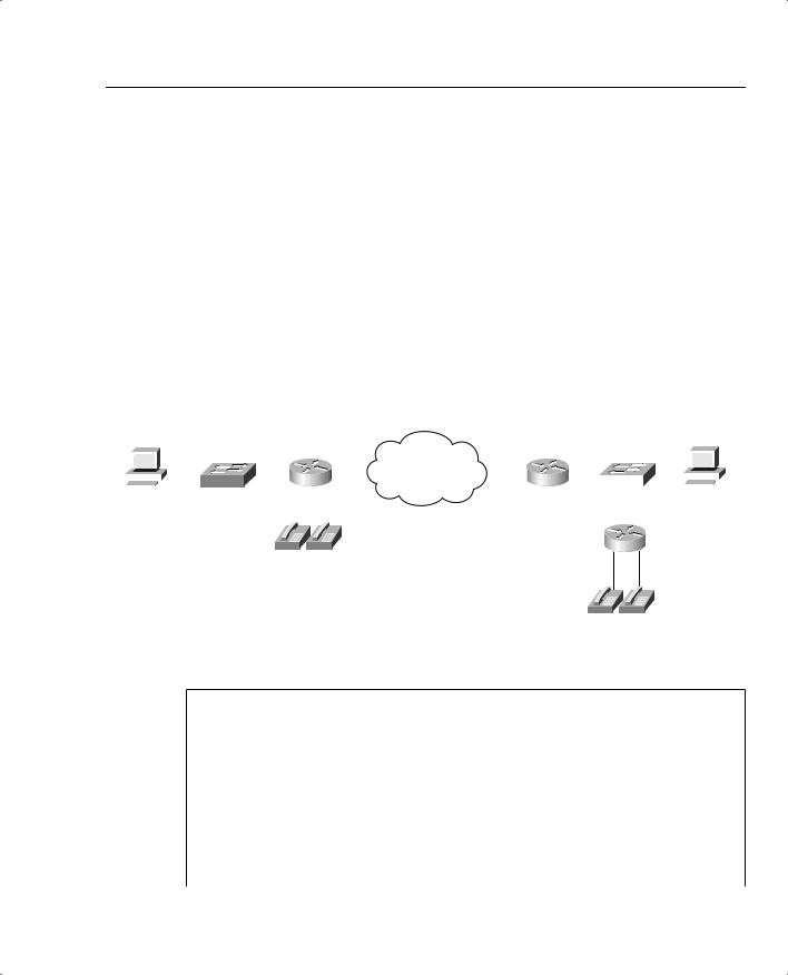
To configure RTP header compression on point-to-point links, you perform a similar exercise as you did for TCP in Example 7-3, except you use the rtp keyword rather than the tcp keyword to enable RTP header compression. For a little variety, however, the next example shows RTP header compression, as enabled on a Frame Relay link between R3 and R1. The network used in this example matches Figure 7-4, shown in the Frame Relay payload compression example. Example 7-4 shows the configuration and statistics.

Example 7-4 Frame Relay RTP Header Compression on R3

R3#show running-config

Building configuration...

!

!Lines omitted for brevity

interface Serial0/0

description connected to FRS port S0. Single PVC to R1. no ip address

encapsulation frame-relay load-interval 30

clockrate 128000

interface Serial0/0.1 point-to-point

description point-point subint global DLCI 103, connected via PVC to DLCI 101 (R1) ip address 192.168.2.253 255.255.255.0

frame-relay interface-dlci 101 frame-relay ip rtp header-compression

!Portions omitted for brevity

!

R3#show frame-relay ip rtp header-compression

DLCI 101

Link/Destination info: point-to-point dlci

Interface Serial0/0:


Rcvd:

18733 total,

18731 compressed, 2 errors


0 dropped, 0

buffer copies, 0 buffer failures


Sent:

16994 total,

16992 compressed,


645645 bytes

saved, 373875 bytes sent


2.72 efficiency improvement factor

Connect:

256 rx slots, 256 tx slots,


0 long searches, 2 misses 0 collisions, 0 negative cache hits


99% hit ratio, five minute miss rate 0 misses/sec, 0 max