

842 Appendix B: Topics on the CCIP QoS Exam
clause, clause 10, matches the community set by R3 by referring to IP community list 1 using the match community 1 command. The community list, created in the single global command ip community-list 1 permit 4:50, just matches all BGP routes whose community string contains 4:50. Route map mark-prec4-comm sets IP precedence 4 for BGP routes that match the community sting. The second route map clause, clause 20, matches all routes because no explicit match statement is configured, and sets the IP precedence to 0 for these routes.
The packet-marking function, as opposed to the route-marking function, is enabled by the bgppolicy interface subcommands, which are exactly the same as saw in Chapter 3 in Example 3-10.
QPPB: The Hidden Details
As mentioned earlier, QPPB confuses most people the first time they learn about it. Therefore, you should understand a bit more about it. The first aspect of QPPB you should understand pertains to what BGP updates contain in support of QPPB, and the second aspect of QPPB you should understand is what really happens when QPPB marks a route.
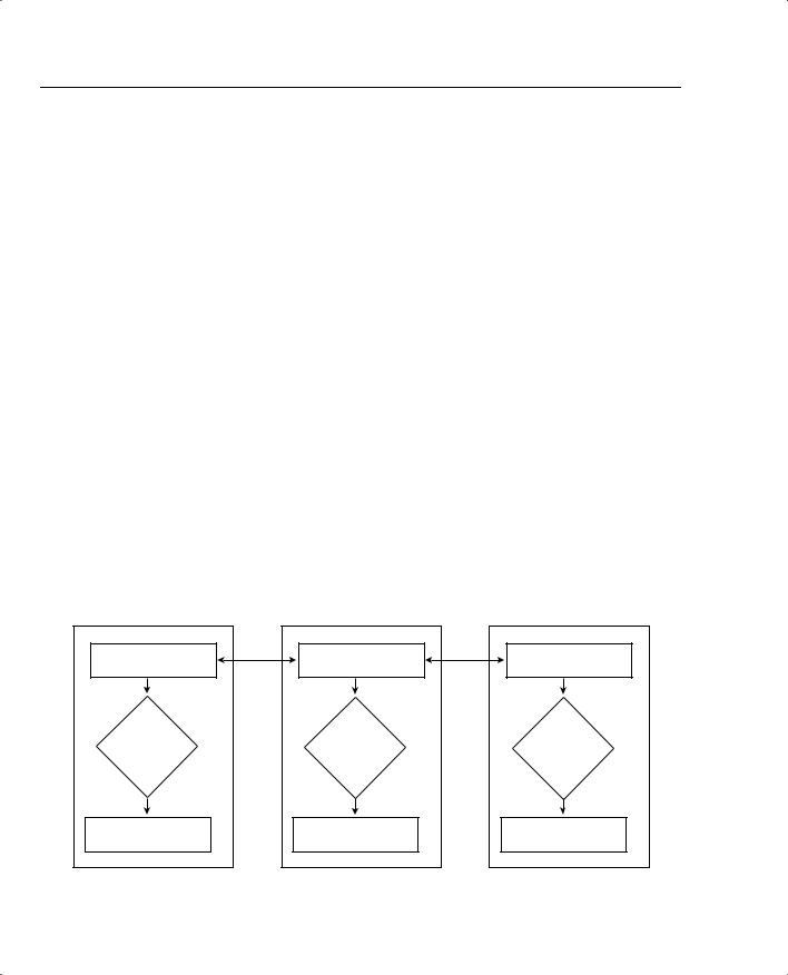
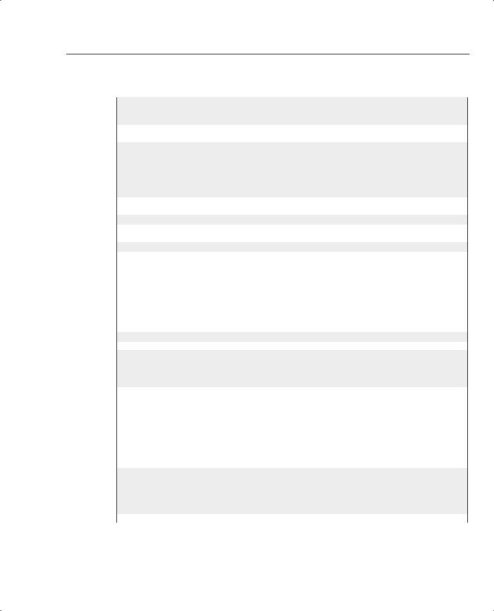
First, BGP updates do not include the IP precedence or QoS group value inside the BGP update. QPPB reacts to the information in a normal BGP update to perform QoS marking of BGP routes, and then in turn performs packet marking based on the marked routes. In other words, BGP RFCs did not add any specification for adding a QoS marking field to the information inside the update. Therefore, to mark based on BGP routes, QPPB uses preexisting fields in the BGP update, such as the autonomous system path and the community attribute. In fact, the BGP-4 RFCs added the community attribute to provide a flexible field for marking BGP routes for future unforeseen purposes, such as QPPB. Figure B-4 depicts the general idea:
Figure B-4 BGP Updates and QPPB Route Marking: No QoS-Marked Fields in BGP Update
R3 |
|
R2 |
|
R1 |
BGP Table Including |
BGP |
BGP Table Including |
BGP |
BGP Table Including |
Path Attributes |
Updates |
Path Attributes |
Updates |
Path Attributes |
Interpret |
|
Interpret |
|
Interpret |
BGP Info, |
|
BGP Info, |
|
BGP Info, |
Mark Route |
|
Mark Route |
|
Mark Route |
Routing Table, with |
|
Routing Table, with |
|
Routing Table, with |
Marked Routes |
|
Marked Routes |
|
Marked Routes |

Classification and Marking 843
When marking IP precedence in packets, QPPB marks the same field already covered in depth in this chapter—the first 3 bits of the ToS byte. When QPPB marks the QoS group, it actually marks a header that is added to the packet when passing through a 7500, GSR, or ESR series router. However, QPPB must mark the route first, and then mark the packet based on the route that matches the source or destination IP address in the packet. To understand what mark the route really means, you must take at least a cursory look at Cisco Express Forwarding (CEF).
IOS provides several different processing paths in software for forwarding packets. Process switching is one of those paths, and is the most processor-intensive path. Fast switching is another switching path still in use today. CEF is yet another switching or forwarding path, and CEF has been designed to be very efficient. Other switching paths have also been added over the years, some specific to particular hardware models. The one thing all these optimized forwarding paths have in common is that they optimize for the forwarding process by streamlining two functions: the process of matching the correct route in the routing table, and the process of building and adding the new data-link header to the packet.
CEF optimizes forwarding by creating a new table that includes entries for the routes in the routing table. This table is called the Forwarding Information Base (FIB). The FIB optimizes the process of locating a route by performing a table lookup in the FIB rather than the lessefficient table lookup of the routing table. In other words, CEF switching crunches the routing table into the FIB, and then uses the FIB to make the forwarding decisions. (This in itself is somewhat of an oversimplification of CEF; for more detail, refer to Vijay Bollapragada’s Inside Cisco IOS Software Architecture [Cisco Press, 2000].)
CEF optimizes the creation of new data-link headers by creating a table that contains the new data-link header associated with each next-hop IP address in the FIB. By doing so, when FIB table lookup is complete, the header can be added to the packet with little processing.
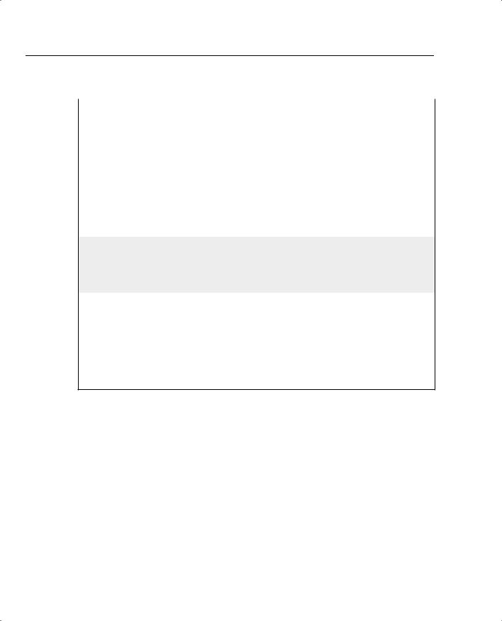
When QPPB marks a route, it actually marks either or both of the two fields inside each entry in the FIB. The FIB contains IP precedence and QoS group fields in order to support QPPB. Therefore, when CEF crunches the routing table to create FIB entries, when QPPB is configured, the appropriate FIB precedence and QoS group fields are set. Figure B-5 shows the general idea.
844 Appendix B: Topics on the CCIP QoS Exam
Figure B-5 “Marking the Route”: Marking the CEF FIB
R2
BGP Table Including
Path Attributes that
Imply a QoS Mark
IP Routing Table, with
No QoS Marked Values
Apply QPPB
Table-map
CEF FIB, with QoS
Marked Values
QPPB Summary
QPPB provides convenient classification and marking when BGP is already in use. Because QPPB bases classification decisions on BGP information, however, the classification process should consume less overhead per packet than the other generalized classification and marking tools.
Q&A for QPPB
1When configuring QPPB to set a precedence value of 4, describe the two places in which precedence 4 is set. Specifically, note when it is marked in routing updates that flow between routers, in user packets that flow between routers, and in tables in a single router.
Answer: QPPB marks the CEF FIB internally to a router. In this case, the FIB entry for some routes is marked with precedence 4, and user packets in turn are marked precedence 4 based on the FIB entry. The BGP routing updates never include the marked value of precedence 4.
2Imagine a router for which QPPB is enabled on interface E0. Describe the process that QPPB performs on this packet. Refer to the information that must be available to QPPB before the packet can be marked. Assume IP precedence is marked.
Answer: QPPB processes the incoming packet. Depending on the configuration, QPPB performs a table lookup on the source or destination IP address of the packet, as compared with the CEF FIB. The FIB entry may have a precedence value assigned to it. If so, QPPB marks the packet with that precedence value. QPPB must have already processed BGP routing information, and marked the FIB entry, before the packet can be marked.

Congestion Management (Queuing) 845
3What command enables QPPB packet marking on an interface, based on the source IP address of the packet, for packets entering the interface?
Answer: The bgp-policy source ip-prec-map interface subcommand enables QPPB for packets entering the interface.
4What command enables QPPB packet marking on an interface, based on the destination IP address of the packet, for packets exiting the interface?
Answer: QPPB only processes packets entering an interface, so this is a trick question. No command could perform the action of enabling a QPPB packet marking for packets exiting an interface.
5What RFC defines the BGP NLRI extensions that support QoS marking in BGP updates?
Answer: This is a trick question. The marked value is not carried in the BGP update; QPPB looks at existing BGP attributes, such as autonomous system path and community, and makes a choice to mark the routing (FIB) entry based on those existing BGP fields.
6What BGP path attributes can QPPB use for classification?
Answer: QPPB can match the BGP autonomous system path and community fields.
7What fields can QPPB mark?
Answer: QPPB can mark the IP Precedence or the QoS Group fields, and the IP ToS bits.
Congestion Management (Queuing)
Chapter 4, “Congestion Management,” of this book covers congestion management tools—in other words, queuing tools. The QoS exam covers several variations of Weighted Fair Queuing (WFQ) and the Modified Deficit Round-Robin (MDRR) tool that is useful on Gigabit Switch Routers (GSRs). These topics are covered next. Also included here is coverage of Priority Queuing (PQ) and Custom Queuing (CQ) configuration, which is also found only on the QoS exam.
PQ Configuration
PQ configuration resembles access-control list (ACL) configuration, except the result is to queue a packet rather than discarding it. Global commands are used to define the logic for classifying packets by matching header fields, and an interface subcommand is used to enable PQ on an interface. Example configurations for PQ follow Tables B-4 and B-5, which list the configuration and exec commands related to PQ, respectively.

848 Appendix B: Topics on the CCIP QoS Exam
Example B-5 Priority Queuing, VoIP in High Queue, All Else in Normal Queue (Continued)
priority-list 5 protocol ip high list 120
R3#show queue serial 0/0
Output queue for Serial0/0 is 26/60
Packet 1, linktype: ip, length: 1404, flags: 0x88
source: 192.168.3.100, destination: 192.168.1.100, id: 0xF560, ttl: 127, TOS: 0 prot: 6, source port 2831, destination port 1668
data: 0x0B0F 0x0684 0x79EB 0x0D2A 0x05B4 0x0FF5 0x5010 0x4510 0x5BF8 0x0000 0x6076 0xEEFD 0xFBB6 0xCC72
Packet 2, linktype: ip, length: 724, flags: 0x88
source: 192.168.3.100, destination: 192.168.1.100, id: 0xF561, ttl: 127, TOS: 0 prot: 6, source port 80, destination port 1667
data: 0x0050 0x0683 0x79C1 0x0930 0x05B3 0xE88E 0x5010 0x41C5 0x276E 0x0000 0xDA9B 0x48F7 0x7F64 0x7313
Packet 3, linktype: ip, length: 724, flags: 0x88
source: 192.168.3.100, destination: 192.168.1.100, id: 0xF562, ttl: 127, TOS: 0 prot: 6, source port 80, destination port 1666
data: 0x0050 0x0682 0x79BC 0xE875 0x05B3 0xE2C6 0x5010 0x441A 0xA5A2 0x0000 0x8071 0x4239 0x5906 0xD18C
! Several lines omitted for brevity
R3#show queueing interface serial 0/0
Interface Serial0/0 queueing strategy: priority
Output queue utilization (queue/count) high/13593 medium/0 normal/206 low/0
R3#show queueing priority
Current DLCI priority queue configuration:
Current priority queue configuration:
List |
Queue |
Args |
|
5 |
high |
protocol ip |
list 120 |
|
|
|
|
R3#show int s 0/0
Serial0/0 is up, line protocol is up Hardware is PowerQUICC Serial
Description: connected to FRS port S0. Single PVC to R1. MTU 1500 bytes, BW 1544 Kbit, DLY 20000 usec,
reliability 255/255, txload 9/255, rxload 8/255 Encapsulation FRAME-RELAY, loopback not set Keepalive set (10 sec)
LMI enq sent 79, LMI stat recvd 70, LMI upd recvd 0, DTE LMI up LMI enq recvd 0, LMI stat sent 0, LMI upd sent 0
LMI DLCI 1023 LMI type is CISCO frame relay DTE
Broadcast queue 0/64, broadcasts sent/dropped 165/2, interface broadcasts 149 Last input 00:00:02, output 00:00:00, output hang never
Last clearing of "show interface" counters 00:13:25
Congestion Management (Queuing) 849
Example B-5 Priority Queuing, VoIP in High Queue, All Else in Normal Queue (Continued)
Input queue: 0/75/0/0 (size/max/drops/flushes); Total output drops: 2 Queueing strategy: priority-list 5
Output queue (queue priority: size/max/drops):
high: 4/20/2, medium: 0/40/0, normal: 20/60/0, low: 0/80/0
!
! Lines omitted for brevity.
Example B-5 uses only one priority-list command in this case, putting voice traffic into the High queue and letting the rest of the traffic be placed in the Normal queue by default. The priority-list 5 protocol ip high list 120 command matches all IP packets that are permitted by ACL 120, which matches all VoIP User Datagram Protocol (UDP) ports. The priority-group 5 interface subcommand enables PQ on S0/0, linking PQ list 5 with the interface.
Two similar commands display some limited information about PQ. First, the show queue command lists brief information about packets currently in the queue. Notice that some information is listed for each packet in the queue; in Example B-5, a packet that was sent by the web server (source port 80) is highlighted. Also note that none of the stanzas describing the packets in the queue shows a voice packet, with UDP ports between 16384 and 32767. Because PQ always serves the High queue first, you would need to have more voice traffic being sent into the network than the speed of the interface before packets would ever actually back up into the High queue. Therefore, it is rare to see queue entries for packets in the High queue.
The show queueing interface command lists configuration information about PQ and statistical information about how many packets have been placed into each queue. Note that no packets have been placed into the Medium or Low queues, because priority-list 5 matches VoIP packets, placing them in the High queue, with all other packets defaulting to the Normal queue. The show queueing priority command lists information about the configuration of PQ.
Finally, the output of the show interfaces command states that PQ is in use, along with statistics about each queue. The current number of packets in each queue, the maximum length of each queue, and the cumulative number of tail drops is listed for each of the four queues.
Good QoS design calls for the marking of packets close to the source of the packet. The next example (Example B-6) accomplishes the same queuing goals as the preceding example, but in this case, PQ relies on the fact that the packets have been marked before reaching R3’s S0/0 interface. In a real network, the packets could be marked on one of the LAN switches, or in an IP Phone, or by the computers in the network. This example shows the packets being marked upon entering R3’s E0/0 interface, as shown in Example 3-1 in Chapter 3. Example B-6 shows the revised configuration based on the following criteria:
•All VoIP payload traffic has been marked with DSCP EF; place this traffic in the High queue.
•All other traffic has been marked with DSCP BE; place this traffic in the Normal queue.
850 Appendix B: Topics on the CCIP QoS Exam
Example B-6 Priority Queuing, DSCP EF in High Queue, All Else in Normal Queue
R3#show running-config
!Portions omitted for brevity
!Next several lines are CB Marking configuration, not PQ configuration class-map match-all all-else
match any
class-map match-all voip-rtp match ip rtp 16384 16383
policy-map voip-and-be class voip-rtp
set ip dscp 46 class class-default
set ip dscp 0
interface Ethernet0/0
description connected to SW2, where Server1 is connected ip address 192.168.3.253 255.255.255.0
load-interval 30
service-policy input voip-and-be
interface Serial0/0
description connected to FRS port S0. Single PVC to R1. no ip address
encapsulation frame-relay load-interval 30
priority-group 6 clockrate 128000
interface Serial0/0.1 point-to-point
description point-point subint global DLCI 103, connected via PVC to DLCI 101 (R1) ip address 192.168.2.253 255.255.255.0
frame-relay interface-dlci 101
!Portions omitted for brevity
!
access-list 121 permit ip any any dscp ef
!
priority-list 6 protocol ip high list 121
!
! Portions omitted for brevity
R3#show queueing priority
Current DLCI priority queue configuration:
Current priority queue configuration:
List |
Queue |
Args |
|
6 |
high |
protocol ip |
list 121 |
R3#show interface s 0/0 |
|
||
Serial0/0 is up, line protocol is up
Congestion Management (Queuing) 851
Example B-6 Priority Queuing, DSCP EF in High Queue, All Else in Normal Queue (Continued)
Hardware is PowerQUICC Serial
Description: connected to FRS port S0. Single PVC to R1. MTU 1500 bytes, BW 1544 Kbit, DLY 20000 usec,
reliability 255/255, txload 20/255, rxload 6/255 Encapsulation FRAME-RELAY, loopback not set Keepalive set (10 sec)
LMI enq sent 29, LMI stat recvd 29, LMI upd recvd 0, DTE LMI up LMI enq recvd 0, LMI stat sent 0, LMI upd sent 0
LMI DLCI 1023 LMI type is CISCO frame relay DTE
Broadcast queue 0/64, broadcasts sent/dropped 68/0, interface broadcasts 63 Last input 00:00:01, output 00:00:00, output hang never
Last clearing of "show interface" counters 00:04:50
Input queue: 0/75/0/0 (size/max/drops/flushes); Total output drops: 751 Queueing strategy: priority-list 6
Output queue (queue priority: size/max/drops):
high: 0/20/0, medium: 0/40/0, normal: 4/60/751, low: 0/80/0
!
!Portions omitted for brevity.
In Example B-6, priority-list 6 contains a single entry, referring to ACL 121, which matches all IP packets with DSCP EF. The priority-group 6 command enables PQ on S0/0. Before the PQ configuration can actually do what the requirements suggest, the packets must be marked. The policy-map voip-and-be command matches VoIP packets based on their UDP port numbers, and marks them on ingress to interface e0/0. Note that unlike the preceding example, when an ACL matched all UDP ports between 16384 and 32767, this example matches only evennumbered ports, which are the ports actually used for VoIP payload. (The odd-numbered ports are used for voice signaling.) The match ip rtp 16384 16383 command matches the same range of port numbers as ACL 120, except it only matches the even (payload) ports.
PQ can only support four different classifications of packets, because it only has four queues. Example B-7 shows all four queues being used. The following criteria is used for queuing packets on R3’s S0/0 interface:
•VoIP payload is placed into the High queue.
•NetMeeting voice and video from Server1 to Client1 is placed in the Medium queue.
•Any HTTP traffic is placed into the Normal queue.
•All other traffic is placed into the low queue.
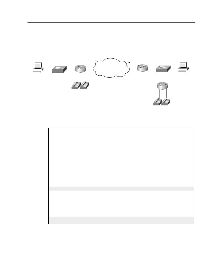
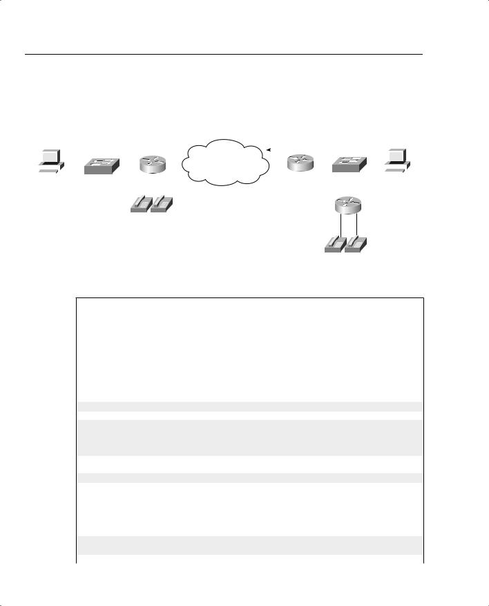
The same network used in the preceding example, as shown in Figure B-6, is used for this example, too.
852 Appendix B: Topics on the CCIP QoS Exam
Example B-7 PQ Example: VoIP in High, NetMeeting in Medium, HTTP in Normal, and All Else in Low Queue
access-list 150 permit udp host 192.168.1.100 range 16384 32767 192.168.3.0 0.0.0.255
range 16384 32767
!
access-list 151 permit udp any range 16384 32768 any range 16384 32768
!
access-list 152 permit tcp any eq www any access-list 152 permit tcp any any eq www
!
priority-list 8 protocol ip medium list 150 priority-list 8 protocol ip high list 151 priority-list 8 protocol ip normal list 152 priority-list 8 default low
!
interface serial 0/0 priority-group 8
Note a couple of points from the example. First, there is no need to match the traffic that goes into the Low queue, because the priority-list 8 default low command makes the Low queue the default queue for unmatched packets. Second, note that ACL 152 matches web traffic from web servers, as well as to web servers. In this limited example, you only needed to check for packets from the web server when performing queuing on output of R3’s S0/0 interface. Because one day you might have traffic going to a web server exiting R3’s S0/0 interface, however, you might want to go ahead and match all web traffic as shown in the ACL.
Finally, one last example shows the equivalent configuration as shown in Example B-7, but with the assumption that the traffic had been marked before reaching R3’s S0/0 interface. Again, the packets are marked upon entering R3’s E0/0, using CB marking. The criteria used for the final example, whose configuration is shown in Example B-8, is as follows:
•VoIP payload is marked with DSCP EF (decimal 46); put this traffic in the High queue.
•NetMeeting voice and video from Server1 to Client1 has been marked with DSCP AF41 (decimal 34); place this traffic in the Medium queue.
•Any HTTP traffic has been marked with DSCP AF22 (decimal 20); place this traffic in the Normal queue.
•All other traffic has been marked with DSCP BE (decimal 0); place this traffic in the Low queue.
Example B-8 PQ Example: DSCP EF in High, DSCP AF41 in Medium, DSCP AF22 in Normal, and All Else in Low Queue
R3#show running-config
! Portions omitted for brevity class-map match-all http-all
match protocol http class-map match-all voip-rtp

854 Appendix B: Topics on the CCIP QoS Exam
Example B-8 PQ Example: DSCP EF in High, DSCP AF41 in Medium, DSCP AF22 in Normal, and All Else in
Low Queue (Continued)
priority-list 7 default low
R3#show queueing int s 0/0
Interface Serial0/0 queueing strategy: priority
Output queue utilization (queue/count) high/42092 medium/1182 normal/52 low/3242
As seen in Example B-8, if the packets have already been marked, PQ can simply match the DSCP field. Routers that forward these packets later can also just configure PQ, and match the DSCP field. Note that PQ needs to refer to an ACL to match the DSCP field, whereas some other queuing tools can refer directly to the DSCP field without using an ACL. Another interesting point to note in this configuration is that the CB marking configuration used network-based application recognition (NBAR) with the match protocol http command to match all web traffic, and then set those packets with DSCP 20. Example B-7 showed why you might want to match all web traffic, but the configuration used two entries to match all web traffic (ACL 152). With NBAR, you can match all web traffic, regardless of whether it is coming from or going to a web server.
CQ Configuration
CQ configuration resembles PQ configuration. Global commands are used to define the logic for classifying packets by matching header fields, and an interface subcommand is used to enable CQ on an interface. Example configurations for CQ follow Tables B-6 and B-7, which list the configuration and exec commands related to CQ, respectively.
Table B-6 |
Configuration Command Reference for CQ |
|
|
|
|
|
Command |
Mode and Function |
|
|
|
|
queue-list list-number protocol protocol-name |
Global configuration command; creates a custom |
|
queue-number queue-keyword keyword-value |
queue list entry, sets classification first by protocol, |
|
|
and then further refines it with keywords. Also |
|
|
identifies the queue into which to place matched |
|
|
packets. (See Example B-9 for a list of keywords.) |
|
|
|
|
queue-list list-number interface interface-type |
Global configuration command; creates a custom |
|
interface-number queue-number |
queue list entry, sets classification based on |
|
|
incoming interface, and then identifies queue into |
|
|
which to place matched packets. |
|
|
|
|
queue-list list-number queue queue-number |
Global config command; sets the byte count for the |
|
byte-count byte-count-number |
specified queue, which is the number of bytes taken |
|
|
from this queue each pass. |
|
|
|

856 Appendix B: Topics on the CCIP QoS Exam
Figure B-7 |
Network Used with CQ Configuration Examples |
|
|
|
|
|
|
|
|
|
|
||||||||||||||
|
|
|
|
|
|
|
|
|
|
|
|
|
|
|
|
|
|
|
|
|
|
|
|
|
|
|
|
|
|
|
|
|
|
|
|
|
|
|
|
|
|
Custom Queue: |
|
|
|
|
|
|
|
|
|
|
|
|
|
|
|
|
|
|
|
|
|
|
|
|
|
VoIP into One Queue |
|
|
|
|
|
|
|
||
|
Note: All IP Addresses Begin 192.168. |
|
|
|
All Else into a Different Queue |
|
|
|
|
|
|
|
|||||||||||||
|
|
|
|
|
|
|
|
|
Server1 |
||||||||||||||||
|
Client1 |
|
|
|
|
|
|
|
|
|
|
|
|
|
|
||||||||||
|
|
|
|
|
|
|
|
1.252 |
|
|
|
|
2.252 |
|
|
|
|
|
|
|
|
|
|
||
|
|
|
|
|
|
|
|
|
|
|
|
|
|
|
|
|
|
|
|
|
|
||||
|
|
|
|
|
|
|
|
|
|
|
|
|
|
|
|
|
|
|
|
|
|
|
|
|
|
|
|
|
|
|
|
|
SW1 |
|
|
|
R1 |
|
s0/0 |
|
s0/0 |
R3 |
SW2 |
|
|
|
|
|
|||
|
|
|
|
|
|
|
|
|
|
|
|
|
|
|
|||||||||||
|
|
|
|
|
|
|
|
|
|
|
|
|
|
|
|
|
|
|
|
|
3.100 |
|
|
||
|
1.100 |
|
|
|
|
|
|
|
|
|
|
|
|
|
|
|
|
|
|||||||
|
|
|
|
|
|
|
|
|
|
|
|
|
|
|
|
|
|
|
|
3.254 |
|
|
|
|
|
|
|
|
|
|
|
|
|
|
|
|
|
|
|
|
|
|
|
|
|
|
|
|
|
|
|
|
|
|
|
|
|
|
|
|
|
|
|
|
|
|
|
|
|
|
|
|
|
|
|
|
|
|
|
|
|
|
|
|
|
|
|
|
|
|
|
|
|
|
|
|
|
|
|
|
|
|
|
R4
101 102
301 302
Example B-9 Custom Queuing: VoIP in High Queue, All Else in Normal Queue
R3(config)#queue-list 1 protocol ip 1 ?
|
fragments |
|
Prioritize |
fragmented IP packets |
|
|||
|
gt |
|
|
|
|
Classify packets greater than a specified |
size |
|
|
|
|
|
|
|
To specify |
an access list |
|
|
list |
|
|
|
||||
|
lt |
|
|
|
|
Classify packets less than a specified size |
||
|
|
|
|
|
Prioritize |
TCP packets 'to' or 'from' the |
specified port |
|
|
tcp |
|
|
|||||
|
udp |
|
|
|
Prioritize |
UDP packets 'to' or 'from' the |
specified port |
|
|
<cr> |
|
|
|
|
|
||
R3(config)#^Z |
|
|
|
|||||
R3#show running-config
access-list 120 permit udp any range 16383 32767 any range 16383 32767
!
queue-list 5 protocol ip 2 list 120 queue-list 5 queue 2 byte-count 5000 queue-list 5 queue 1 byte-count 2500 queue-list 5 queue 2 limit 30
!
interface serial0/0 custom-queue-list 5
!
R3#show queueing custom
Current custom queue configuration:
List |
Queue |
Args |
|
5 |
2 |
protocol ip |
list 120 |
51 byte-count 2500
52 byte-count 5000 limit 30
Congestion Management (Queuing) 857
Example B-9 Custom Queuing: VoIP in High Queue, All Else in Normal Queue (Continued)
R3#show queueing int s 0/0
Interface Serial0/0 queueing strategy: custom
Output queue utilization (queue/count)
0/15 1/91 2/3549 3/0 4/0 5/0 6/0 7/0 8/0 9/0 10/0 11/0 12/0 13/0 14/0 15/0 16/0
R3#show int s 0/0
Serial0/0 is up, line protocol is up Hardware is PowerQUICC Serial
Description: connected to FRS port S0. Single PVC to R1. MTU 1500 bytes, BW 1544 Kbit, DLY 20000 usec,
reliability 255/255, txload 9/255, rxload 8/255 Encapsulation FRAME-RELAY, loopback not set Keepalive set (10 sec)
LMI enq sent 1, LMI stat recvd 1, LMI upd recvd 0, DTE LMI up LMI enq recvd 0, LMI stat sent 0, LMI upd sent 0
LMI DLCI 1023 LMI type is CISCO frame relay DTE
Broadcast queue 0/64, broadcasts sent/dropped 4/0, interface broadcasts 3 Last input 00:00:00, output 00:00:00, output hang never
Last clearing of "show interface" counters 00:00:12
Input queue: 0/75/0/0 (size/max/drops/flushes); Total output drops: 282 Queueing strategy: custom-list 5
Output queues: (queue #: size/max/drops)
0: 0/20/0 1: 6/20/0 2: 28/30/282 3: 0/20/0 4: 0/20/0 5: 0/20/0 6: 0/20/0 7: 0/20/0 8: 0/20/0 9: 0/20/0 10: 0/20/0 11: 0/20/0 12: 0/20/0 13: 0/20/0 14: 0/20/0 15: 0/20/0 16: 0/20/0
5 minute input rate 52000 bits/sec, 102 packets/sec
5 minute output rate 60000 bits/sec, 73 packets/sec
1394 packets input, 89409 bytes, 0 no buffer
Received 0 broadcasts, 0 runts, 0 giants, 0 throttles
0 input errors, 0 CRC, 0 frame, 0 overrun, 0 ignored, 0 abort 1085 packets output, 102851 bytes, 0 underruns
0 output errors, 0 collisions, 0 interface resets
0 output buffer failures, 0 output buffers swapped out
0 carrier transitions
DCD=up DSR=up DTR=up RTS=up CTS=up
The configuration for this scenario only requires a few commands. The queue-list 5 protocol ip 2 list 120 command causes CQ to match all packets permitted by ACL 120 and to place these packets into Queue 2. CQ uses Queue 1 for unmatched packets, so no other classification commands are required. The byte count for each queue defaults to 1500 bytes; in this case, the criteria specified that CQ should give about 2/3 of the bandwidth to the VoIP traffic, so queue 2 was assigned a byte count of 5000, and Queue 1 a byte count of 2500. At a 64-kbps clock rate, each complete cycle takes a little less than a second. Finally, to enable CQ list 5, the customqueue interface subcommand was used.
858 Appendix B: Topics on the CCIP QoS Exam
IOS uses the same show commands to display information about CQ as it does for PQ. The show queue command lists brief information about packets in the queue at the present time (not shown in the example). The show queueing interface command lists configuration information about CQ and statistical information about how many packets have been placed into each queue. In the example, Queue 2 has had a total of 3549 packets pass through it. Also note that no packets have been placed into Queues 3 through 16, because CQ list 5 does not classify packets into Queues 3 through 16. The show queueing custom command lists information about the configuration of CQ. The output of the show interfaces command states that CQ is in use, along with statistics about each queue. The current number of packets in each queue, the maximum length of each queue, and the cumulative number of tail drops are listed for each of the 16 queues.
You may have noticed that Queue 0 shows up in a couple of commands. CQ uses a special queue, Queue 0, which is used for important high-priority packets generated by the router. Routing protocol updates are considered high priority, for instance, so these packets are placed into Queue 0. CQ treats Queue 0 as a priority queue—that is, when packets are waiting in Queue 0, CQ interrupts its normal scheduling logic, takes the packet from Queue 0 next, and then resumes the scheduling process. CQ does not allow packets to be explicitly classified into Queue 0.
Stepping back from the configuration for a moment, consider the time required to service 2500 bytes from Queue 1, and then 5000 bytes from Queue 2, at 64 kbps. It requires roughly .875 seconds total, with roughly 310 ms to service Queue 1, and the rest to service Queue 2. So, if Queue 1 has many packets, the voice packet in Queue 2 that is the next packet to get serviced, after Queue 1 gets to send its 2500 bytes, has to wait an extra 310 ms! So, this example, although giving voice 2/3 of the bandwidth, does not actually give voice very good performance.
Good QoS design calls for the marking of packets close to the source of the packet. The next example accomplishes the same queuing goals as the preceding example, but CQ relies on the fact that the packets have been marked before reaching R3’s S0/0 interface. In a real network, the packets could be marked on one of the LAN switches; for review, however, this example shows the packets being marked upon entering R3’s E0/0 interface, just as shown in Example 3-1 in Chapter 3. Example B-10 shows the revised configuration based on the following criteria:
•All VoIP payload traffic has been marked with DSCP EF; place this traffic in Queue 1.
•All other traffic has been marked with DSCP BE; place this traffic in Queue 2.
•VoIP traffic is given about 2/3 of the bandwidth.
Example B-10 Custom Queuing: DSCP EF in Queue 1, All Else in Queue 2
ip cef
!
class-map match-all class-default match any

Congestion Management (Queuing) 861
The same network used in the preceding example, as shown in Figure B-7, is used for this example as well.
Example B-11 CQ Example: VoIP in Queue 1, NetMeeting in Queue 2, HTTP in Queue 3, and All Else in Queue 4
access-list 150 permit udp host 192.168.1.100 range 16384 32767 192.168.3.0 0.0.0.255 range 16384 32767
!
access-list 151 permit udp any range 16384 32768 any range 16384 32768
!
access-list 152 permit tcp any eq www any access-list 152 permit tcp any any eq www
!
queue-list 8 protocol ip 2 list 150 queue-list 8 protocol ip 1 list 151 queue-list 8 protocol ip 3 list 152
queue-list 8 queue 1 byte-count 2500 queue-list 8 queue 2 byte-count 2500 queue-list 8 queue 3 byte-count 2500 queue-list 8 queue 4 byte-count 2500 queue-list 8 default 4
!
interface serial 0/0 custom-queue 8
Distributed Weighted Fair Queuing (dWFQ)
IOS provides three streamlined WFQ options specifically designed for the Cisco 7500 series hardware architecture: distributed WFQ (dWFQ), ToS-based WFQ, and QoS group–based WFQ. The 7500 architecture includes distributed processing on line cards called Versatile Interface Processors (VIPs). Many functions that the general-purpose processor on the Route Switch Processor (RSP) card would normally perform by can instead be distributed to the processor on the VIPs. Distributing the processing can prove very helpful in typical 7500 series configurations that use a large number of line cards and interfaces, relieving processing burden from the general-purpose RSP processor.
You can use WFQ on 7500s without distributing the processing to the VIPs. To do so, just configure WFQ as described in the preceding section. However, Cisco created these other three distributed WFQ options specifically for 7500s, to address some specific needs. In particular, because 7500s tend to have faster WAN interfaces, Cisco created WFQ tools that run more efficiently in a higher-speed environment. One of the key goals of queuing is to reduce delay for the appropriate traffic; these distributed queuing tools are streamlined so that, even on the higher-speed interfaces on the 7500, the queuing process does not artificially delay any packets.