

554 Chapter 8: Call Admission Control and QoS Signaling
Table 8-4 |
CAC Feature Evaluation Criteria (Continued) |
|
|
|
|
|
Evaluation Criteria |
Description |
|
|
|
|
Topology awareness |
Whether the CAC mechanism takes into account the topology of the |
|
|
network, and therefore provides protection for the links and nodes in the |
|
|
topology. |
|
|
|
|
Guarantees QoS for |
Whether the mechanism make a one-time decision before allowing the |
|
duration of call |
call, or whether it also protects the QoS of the call for the duration of the |
|
|
call by reserving the required resources. |
|
|
|
|
Postdial delay |
Whether the mechanism imposes an additional postdial delay because it |
|
|
requires extra messaging or processing during call setup. |
|
|
|
|
Messaging network |
Whether the method uses additional messaging that must be provisioned |
|
overhead |
in the network to gather the information necessary for the CAC decision. |
|
|
|
Local Voice CAC
Local CAC mechanisms are the simplest CAC mechanisms to understand and implement. They operate on the originating gateway and consider only the local conditions of that gateway.
Physical DS0 Limitation
Physical DS0 limitation is a design methodology that limits the number of physical DS0 connections into the gateway. This limitation, in conjunction with other queuing methods, ensures that the gateway can successfully provide IP bandwidth across the WAN for each voice conversation originating from the individual DS0 trunks.
If you have determined that there is 158.4 kbps of WAN bandwidth available to handle 6 simultaneous G.729 calls, for example, DS0 limitations can be implemented by allowing only 6 DS0 connections between the PBX and the originating gateway. These 6 DS0 connections can be in the form of time slots on a digital T1/E1 trunk or individual analog connections, such as FXS, FXO, and E&M trunks.
Figure 8-6 shows a network using physical DS0 limitation to provide CAC.
This CAC design method works well in a situation where there is a TDM-to-IP gateway; however, it not effective in an IP telephony environment where a TDM-to-IP conversion does not exist on the WAN router. Calls originated from IP Phones are presented to the WAN router as an IP stream, without a physical TDM interface to provide a DS0 limitation. Another CAC mechanism must be used to solve this issue. Figure 8-7 demonstrates this concept.

Local Voice CAC 555
Figure 8-6 VoIP Physical DS0 Limitation
Six Physical Connections Between Each PBX and Router
IP Network
R1 |
R2 |
IP Network Designed to Handle up to Six G.729 Calls
Figure 8-7 IP Telephony Physical DS0 Limitation |
|
|
|
Host Site |
Remote Site |
||
|
Frame Relay |
|
|
IP |
Voice Gateway |
Voice Gateway |
IP |
Host Phone |
There are no physical TDM |
|
Remote |
interfaces available in an IP |
|
||
A |
telephony environment to provide |
|
Phone A |
|
DS0 Limitation CAC. |
|
|
IP |
|
|
IP |
|
|
|
|
Host Phone |
|
|
Remote |
B |
|
|
Phone B |
|
Catalyst |
Catalyst |
|
IP |
Switch |
Switch |
IP |
|
|
|
|
Host Phone |
|
|
Remote |
C |
|
|
Phone C |
CallManager |
CallManager |
|
|
Publisher |
Subscriber |
|
|
Restricting physical DS0s on the gateway offers the following advantages:
•Adds no extra CPU usage on the gateway or bandwidth overhead to the network
•Predominant CAC mechanism deployed in toll-bypass networks today

556Chapter 8: Call Admission Control and QoS Signaling
•Protects the quality of voice conversations on the WAN link by limiting the number of voice conversations that are allowed
•Offers a known maximum bandwidth consumption rate based on the total number of possible simultaneous calls
The physical DS0 CAC method has the following limitations:
•Not effective for IP telephony applications
•Limited to relatively simple topologies
•Does not react to link failures or changing network conditions
Table 8-5 evaluates the physical DS0 limitation mechanism against the CAC evaluation criteria described earlier in this chapter.
Table 8-5 DS0 Limitation CAC Evaluation Criteria
Evaluation Criteria |
Value |
|
|
VoX supported |
Independent of the VoX technology used |
|
|
Toll bypass or IP Telephony |
Toll bypass only |
|
|
Platforms and releases |
All voice gateways and all Cisco IOS releases |
|
|
PBX trunk types supported |
All |
|
|
End to end, local, or IP cloud |
Local |
|
|
Per call, interface, or endpoint |
Per DS0/trunk (per call) |
|
|
Topology awareness |
None |
|
|
Guarantees QoS for duration of call |
None |
|
|
Postdial delay |
None |
|
|
Messaging network overhead |
None |
|
|
Max-Connections
Similar to physical DS0 limitation, Max-Connections uses the concept of limiting the number of simultaneous calls to help protect the quality of voice conversations. Unlike physical DS0 limitation, the max-conn command is a physical gateway configuration applied on a per–dial peer basis.
The first advantage that Max-Connections offers over DS0 limitation is the capability to provision for the oversubscription of TDM interfaces on an originating gateway without compromising the quality of the voice conversations being carried over the WAN. Figure 8-8 illustrates a T1 PRI connection from the PSTN and a T1 PRI connection from a PBX. Because a T1 PRI connection has the capability of supporting 23 channels, it is theoretically possible to have 46

Local Voice CAC 557
simultaneous voice conversations on the host site router that are attempting to traverse the WAN to reach endpoints in the remote site.
Figure 8-8 |
Max-Connections |
|
|
|
|
|
|
Host Site |
|
|
Remote Site |
PSTN |
T1 PRI |
|
|
|
|
|
|
|
|
||
|
|
512 kbps |
|
512 kbps |
4 Fax Machines |
|
|
|
Extensions 12xx |
||
|
|
Circuit |
IP WAN |
Circuit |
|
|
|
|
|||
|
|
|
|
|
|
|
|
T1 PRI |
|
|
10 Telephones |
|
|
|
|
Extensions 12xx |
|
|
PBX |
|
|
|
|
|
|
|
|
|
|
Extensions 5xxx |
|
|
|
||
In this example, nine concurrent calls can be supported. Assuming that the data requirement for the IP WAN circuit is 256 kbps, and the codec in use is G.729 at 50 pps without the use of VAD or header compression, the maximum number of calls that can be successfully supported and protected across the 512-kbps WAN link is 9, as shown in the following:
|
((Total----------------------------------------------------------------------------------------------------------------------------------circuit bandwidth) – (Total data requirements)) = Number of protected calls |
|
( Bandwidth per call) |
|
or |
|
(512-----------------------------------------------------kbps – 256 kbps) = 9 calls |
|
26.4 kbps |
|
|
NOTE |
This calculation does not take into account the bandwidth required for routing updates. Instead, |
|
this calculation shows the theoretical maximum number of calls that can traverse this link |
|
assuming no packets other than the listed data requirements are present on the link. |
|
|
If the theoretical maximum of 46 calls over the 2 PRIs is attempted, voice quality for each conversation will suffer greatly, because the current bandwidth of the WAN can provide for a total of 9 simultaneous calls without voice-quality degradation. Example 8-1 shows how you can configure the max-conn command on the host site router to limit the number of simultaneous

558 Chapter 8: Call Admission Control and QoS Signaling
calls on the VoIP dial peer to 9. For this example, assume that all endpoints in the remote site have a directory number consisting of 4 digits, and each directory number begins with the number 12 followed by 2 additional digits.
Example 8-1 Max-Connections Host Site Router
dial-peer voice 100 voip
!Sets the maximum number of connections (active admission control). max-conn 9
destination-pattern 12.. ip precedence 5
session target ipv4:10.1.1.2
Assume that all endpoints in the host site have a directory number consisting of 4 digits and each directory number begins with the number 5 followed by 3 additional digits. Example 8-2 shows how you can configure the max-conn command on the remote site router to limit the number of simultaneous calls on the VoIP dial peer to 9.
Example 8-2 Max-Connections Remote Site
dial-peer voice 100 voip
!Sets the maximum number of connections (active admission control). max-conn 9
destination-pattern 5...
ip precedence 5
session target ipv4:10.1.1.1
The second advantage that Max-Connections offers over DS0 limitation is the capability to limit the number of calls that will be allowed to traverse an IP WAN between multiple sites. Because the max-conn command is applied on a per–dial peer basis, a clear understanding of the call volume desired and the available bandwidth between sites must be achieved. To limit the total number of aggregate voice conversations allowed to traverse the WAN link, the maxconn command must exist on each VoIP dial peer. The aggregate of these configurations must not exceed the bandwidth provisioned for the call volume.
Suppose, for example, that the two additional remote sites are added to the preceding example, each with the same data requirements of 256 kbps. In this scenario, 9 simultaneous calls can be protected from each remote site, as shown in the following:
((Total----------------------------------------------------------------------------------------------------------------------------------circuit bandwidth) – (Total data requirements)) = Number of protected calls |
|
( Bandwidth per call) |
|
or |
|
(512-----------------------------------------------------kbps – 256 kbps) |
= 9 calls |
26.4 kbps |
|

Local Voice CAC 559
The total circuit bandwidth for the host site is increased to a full T1 to handle the two additional sites, as shown in the following:
((Total circuit bandwidth) – (Total data requirements)) / (Bandwidth per call) = Number of protected calls
(1536 kbps – (3 * 256 kbps)) / 26.4 kbps = 29 calls
NOTE |
These calculations do not take into account the bandwidth required for routing updates. Instead, |
|
this calculation shows the theoretical maximum number of calls that can traverse these links |
|
assuming no packets other than the listed data requirements are present on the link. |
|
|
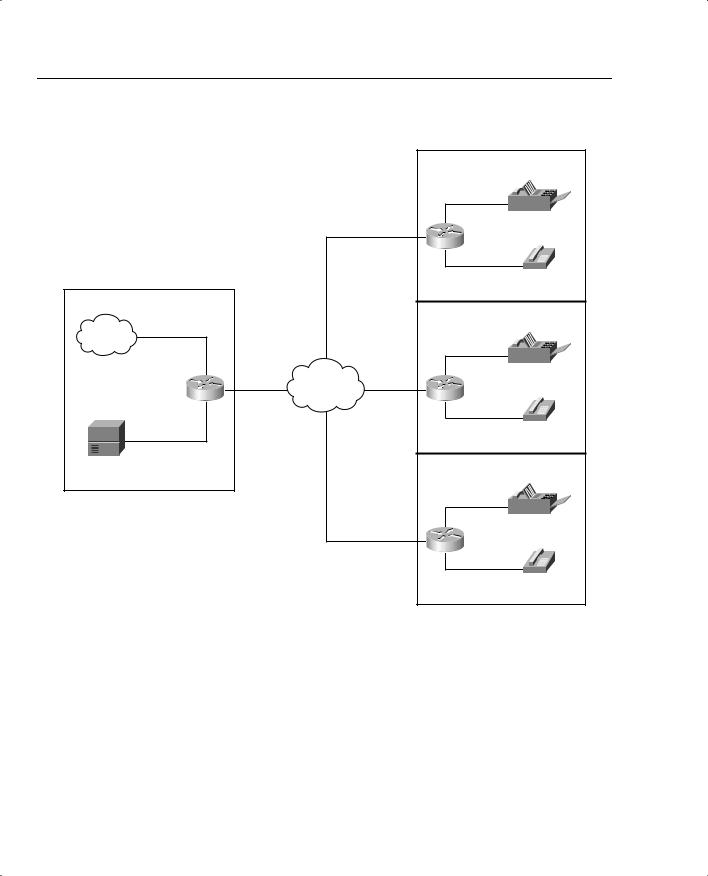
Figure 8-9 illustrates this multiple-site converged network.
Suppose that endpoints in all remote sites have a directory number consisting of 4 digits, and each directory number at Remote Site 1 begins with the number 12 followed by 2 additional digits. Directory numbers at Remote Site 2 begin with the number 13 followed by 2 additional digits. Directory numbers at Remote Site 3 begin with the number 14 followed by 2 additional digits. Example 8-3 shows how you can configure the max-conn command on the host site router to limit the number of simultaneous calls per location on the VoIP dial peer to 9 with an aggregate maximum of 27 calls allowed across the IP WAN.
Example 8-3 Max-Connections Host Site Router per Site
dial-peer voice 1 voip
! 9 calls allowed on VoIP Dial Peer to Remote Site 1 max-conn 9
destination-pattern 12.. ip precedence 5
session target ipv4:10.1.1.2
!
dial-peer voice 2 voip
! 9 calls allowed on VoIP Dial Peer to Remote Site 2 max-conn 9
destination-pattern 13.. ip precedence 5
session target ipv4:10.1.2.2
!
dial-peer voice 3 voip
! 9 calls allowed on VoIP Dial Peer to Remote Site 1 max-conn 9
destination-pattern 14.. ip precedence 5
session target ipv4:10.1.3.2

Local Voice CAC 561
Example 8-4 Max-Connections Remote Site 1
dial-peer voice 1 voip
!VoIP Dial Peer from Remote Site 1 to Host Site max-conn 9
destination-pattern 5...
ip precedence 5
session target ipv4:10.1.1.1
Example 8-5 shows the configuration of the max-conn command at Remote Site 2.
Example 8-5 Max-Connections Remote Site 2
dial-peer voice 1 voip
!VoIP Dial Peer from Remote Site 2 to Host Site max-conn 9
destination-pattern 5...
ip precedence 5
session target ipv4:10.1.2.1
Example 8-6 shows the configuration of the max-conn command at Remote Site 3.
Example 8-6 Max-Connections Remote Site 3
dial-peer voice 1 voip
!VoIP Dial Peer from Remote Site 3 to Host Site max-conn 9
destination-pattern 5...
ip precedence 5
session target ipv4:10.1.3.1
!
After the maximum number of calls specified by the max-conn command has been reached, another mechanism must be used to connect the call via an alternate route. This is achieved by configuring a second dial peer with the same destination pattern, but with a higher preference. Remember that the dial peer with the lowest preference, that can route the call, will be matched.
Example 8-7 shows the configuration of an alternate path using the max-conn command. In this example, dial-peer voice 1 voip is defined with a preference of 1 and dial-peer voice 100 pots is defined with a preference of 2. This indicates that dial peer 1 is preferred over dial peer 100. The two dial peers share the same destination-pattern, meaning that they will both match any dialed digits beginning with 12; however, they will attempt to connect the call using different paths. Dial peer 1 will attempt to connect the call over the IP network sending the dialed digits,

562 Chapter 8: Call Admission Control and QoS Signaling
whereas dial peer 100 will prefix the digits 91404555 to the dialed digits and attempt to connect the call using the PSTN. Dial peer 1 will connect calls until the number of active calls reaches the configured max-conn of 9. When this maximum has been reached, dial peer 1 can no longer connect calls. At this point, dial peer 100 will begin to connect calls using the alternate path to the PSTN.
Example 8-7 Max-Connections Alternate Path
dial-peer voice 1 voip
!Defines first priority for call routing. preference 1
!Sets the maximum number of connections (active admission control). max-conn 9
destination-pattern 12.. ip precedence 5
session target ipv4:10.1.1.2
!
dial-peer voice 100 pots
!Defines second priority for call routing. preference 2
destination-pattern 12.. direct-inward-dial
port 0:D
!Adds prefix 91404555 in front of the called number before sending the digits to the PSTN prefix 91404555
Max-Connections also offer the capability to limit the number of calls allowed on a POTS dial peer by making the value of the max-conn command for that POTS dial peer lower than the physical number of time slots that are available on a T1/E1 connection between the PSTN or a PBX and an originating gateway.
Although the Max-Connections feature is useful in many scenarios, it has the following drawbacks:
•Although it provides some protection for the voice gateway egress WAN link, it provides little or no protection for links in the network backbone.
•It does not work for IP telephony applications that do not use dial peers.
•It is limited to simple topologies.
•It does not react to link failures or changing network conditions.
Table 8-6 evaluates the Max-Connections mechanism against the CAC evaluation criteria described earlier in this chapter.