

QoS: Tuning Bandwidth, Delay, Jitter, and Loss 9
Unfortunately, improving one QoS characteristic might degrade another. Bandwidth defines the capacity of the transmission media. Compression tools reduce the amount of bandwidth needed to send all packets, but the compression process adds some delay per packet and also consumes CPU cycles. Jitter is the variation in delay between consecutive packets, so it is sometimes called “delay variation.” A router can reduce jitter for some traffic, but that usually increases delay and jitter for other traffic flows. QoS features can address jitter problems, particularly the queuing features that have priority queuing for packets that need low jitter. Packet loss can occur because of transmission errors, and QoS mechanisms cannot do much about that. However, more packets might be lost due to queues filling up rather than transmission errors— and QoS features can affect which packets are dropped.
You can think of QoS as “managed fairness” and, conversely, as “managed unfairness.” The real key to QoS success requires you to improve a QoS characteristic for a flow that needs that characteristic, while degrading that same characteristic for a flow that does not need that characteristic. For instance, QoS designs should decrease delay for delay-sensitive traffic, while increasing delay for delay-insensitive traffic.
The next four short sections take a closer look at each of these four traffic characteristics.
Bandwidth
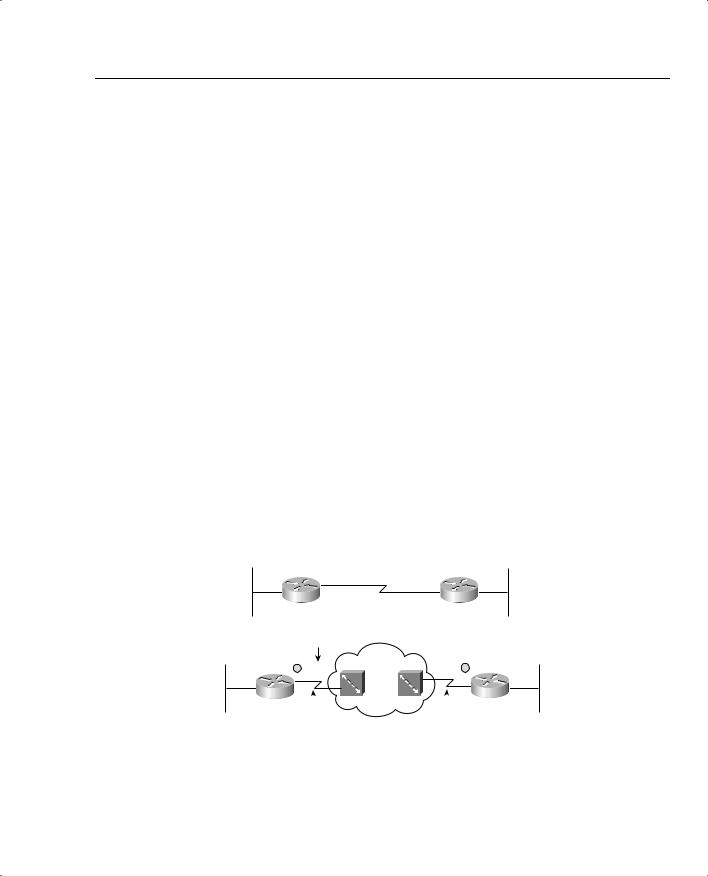
The term “bandwidth” refers to the number of bits per second that can reasonably be expected to be successfully delivered across some medium. In some cases, bandwidth equals the physical link speed, or the clock rate, of the interface. In other cases, bandwidth is smaller than the actual speed of the link. Consider, for example, Figure 1-2, which shows two typical networks, one with a point-to-point serial link, and the other using Frame Relay.
Figure 1-2 Two Similar Networks, One with Point-to-Point, One with Frame Relay
R1 |
R2 |
CIR - 128 kbps
|
|
|
|
|
R4 |
R3 |
|
|
|
||
|
|
|
|||
|
|
|
|
||
Access Rate: 256 kbps |
Access Rate: 1.544 Mbps |
||||
In the point-to-point network, WAN bandwidth equals the physical link speed, or clock rate, on the physical medium. Suppose, for instance, that the link is a 64-kbps link—you could reasonably expect to send 64 kbps worth of traffic, and expect it to get to the other side of the

10 Chapter 1: QoS Overview
link. You would never expect to send more than that, because you cannot send the bits any faster than the clock rate of the interface. Bandwidth, in this case, is indeed rather obvious; you get 64 kbps in both directions.
The Frame Relay network provides a contracted amount of bandwidth. In practice, however, many installations expect more than that! The committed information rate (CIR) defines how much bandwidth the provider guarantees will pass through their network between the data terminal equipment (DTE) at each end of a virtual circuit (VC). That guarantee is a business proposition—a Layer 8 issue using the OSI reference model. On some occasions, you might not actually even get CIR worth of bandwidth. However, the Frame Relay provider commits to engineering a network so that they can support at least the CIRs of their collective VCs. In effect, bandwidth per VC equals the CIR of each VC, respectively.
Unfortunately, bandwidth on multiaccess networks is not that simple. Consider the fact that R3 has a 256-kbps access rate, and R4 has a T1 access rate. When R3 sends, it must send the bits at access rate—otherwise, Layer 1 functions would not work at all. Similarly, R4 must send at T1 speed. One of Frame Relay’s big selling points throughout its large growth years was that you “get something for nothing”—you pay for CIR of x, and you get more than x worth of bandwidth. In fact, many data network engineers design networks assuming that you will get an average of one and a half to two times CIR over each VC. If R3 and R4 send too much, and the provider’s switches have full queues, the frames are discarded, and the data has to be re-sent. If you pay for 128-kbps CIR between R3 and R4, and over time actually send at 192 kbps, or 256 kbps, and it works, how much bandwidth do you really have? Well, on a multiaccess network, such as Frame Relay or ATM, the actual amount of bandwidth is certainly open to argument.
Frame Relay bandwidth might even be less than CIR in practice. Suppose that R4 is the main site, and there are 15 remote sites identical to R3 (including R3). Can you reasonably expect to send at 128 kbps (CIR) to all 15 sites, at the same time, when R4 has a 1.544-Mbps access rate? No! All 15 sites sending at 128 kbps requires 1.920 Mbps, and R4 can only send and receive at 1.544 Mbps. Would an engineer design a network like this? Yes! The idea being that if data is being sent to all VCs simultaneously, either R4 will queue the data (for packets going right to left), or the Frame Relay switch will queue the data (for packets going left to right). If data is not being sent to all 15 remote sites at the same time, you get (at least) 128 kbps to each site that needs the bandwidth at that time. The negative effect is that a larger percentage of packets are dropped due to full queues; however, for data networks that is typically a reasonable tradeoff. For traffic that is not tolerant to loss, such as voice and video, this type of design may not be reasonable.
Throughout this book, when multiaccess network bandwidth is important, the discussion covers some of the implications of using the more conservative bandwidth of CIR, versus the more liberal measurements that are typically a multiple of CIR.

QoS: Tuning Bandwidth, Delay, Jitter, and Loss 11
The clock rate Command Versus the bandwidth Command
When you are using a Cisco router, two common interface commands relate to bandwidth. First, the clock rate command defines the actual Layer 1 bit rate. The command is used when the router is providing clocking, typically when connecting the router using a serial interface to some other nearby device (another router, for instance). The bandwidth command tells a variety of Cisco IOS Software functions how much bandwidth is assumed to be available on the interface. For instance, Enhanced Interior Gateway Routing Protocol (EIGRP) chooses metrics for interfaces based on the bandwidth command, not based on a clock rate command. In short, bandwidth only changes the behavior of other tools on an interface, and it affects the results of some statistics, but it never changes the actual rate of sending bits out an interface.
Some QoS tools refer to interface bandwidth, which is defined with the bandwidth command. Engineers should consider bandwidth defaults when enabling QoS features. On serial interfaces on Cisco routers, the default bandwidth setting is T1 speed—regardless of the actual bandwidth. If subinterfaces are used, they inherit the bandwidth setting of the corresponding physical interface. In Figure 1-2, for example, R3 would have a default bandwidth setting of 1544 (the units are in kbps), as opposed to a more accurate 128, 192, or 256 kbps, depending on how conservative or liberal the engineer can afford to be in this network.
QoS Tools That Affect Bandwidth
Several QoS features can help with bandwidth issues. You’ll find more detail about each of these tools in various chapters throughout this book. For now, however, knowing what each class of QoS tool accomplishes will help you sift through some of the details.
The best QoS tool for bandwidth issues is more bandwidth! However, more bandwidth does not solve all problems. In fact, in converged networks (networks with voice, video, and data), adding more bandwidth might be masking delay problems that are best solved through other QoS tools or through better QoS design. To quote Arno Penzias, former head of Bell Labs and a Nobel Prize winner: “Money and sex, storage and bandwidth: Only too much is ever enough.” If you can afford it, more bandwidth certainly helps improve traffic quality.
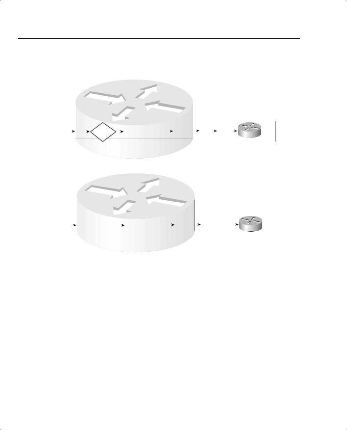
Some link-efficiency QoS tools improve bandwidth by reducing the number of bits required to transmit the data. Figure 1-3 shows a rather simplistic view of the effect of compression, assuming the compression ratio is 2:1. Without compression, with 80 kbps of offered traffic, and only a 64-kbps point-to-point link, a queue will form. The queue will eventually fill, and packets will be dropped off the end of the queue—an action called tail drop. With compression, if a ratio of 2:1 is achieved, the 80 kbps will require only 40 kbps in order to be sent across the link— effectively doubling the bandwidth capacity of the link.
12 Chapter 1: QoS Overview
Figure 1-3 With a 2:1 Compression Ratio Versus No Compression
Router 1
|
|
|
|
|
|
|
|
|
|
|
|
|
|
Tx |
|
|
|
|
|
|
|
|
|
FIFO Queue |
|
Queue 64 kbps |
|
|
|||||||
Offered Load: |
|
|
Compress |
|
|
|
|
|
|
|
|
|
|
|
S0 |
|
|
|
|
|
|
|
|
|
|
|
|
|
|
|
|
|
|||
|
|
|
|
|
|
|
|
|
|
|
|
|
|
|
|
||
80 kbps |
|
|
|
|
|
|
|
|
|
|
|
|
|
40 kbps |
R2 |
||
|
|
|
|
|
|
|
|
|
|
|
|
|
|
||||
|
|
|
|
|
|
|
|
|
|
|
|
|
|
|
|
|
|
Sent
Router 1
|
|
|
|
|
|
|
|
|
|
|
|
|
|
|
Tx |
64 kbps |
|
|
|
|
|
FIFO Queue |
|
Queue |
|
|
|||||||||||
Offered Load: |
|
|
|
S0 |
|
|
||||||||||||
|
|
|
|
|
|
|
|
|
|
|
|
|
|
|
|
|||
|
|
|
|
|
|
|
|
|
|
|
|
|
|
|
|
|
||
80 kbps |
|
|
|
|
|
|
|
|
|
|
|
|
|
|
64 kbps Sent, |
R2 |
||
|
|
|
||||||||||||||||
|
|
Larger Queue Due |
|
|
|
Rest Queued |
|
|
||||||||||
|
|
|
|
|
|
|
||||||||||||
|
|
|
to Congestion |
|
|
|
|
|
|
|||||||||
This book covers several options for compression, some of which happen before the queuing process (as shown in Figure 1-3), and some that happen after the queuing process.
The other QoS tool that directly affects bandwidth is call admission control (CAC). CAC tools decide whether the network can accept new voice and video calls. That permission might be based on a large number of factors, but several of those factors involve either a measurement of bandwidth. For example, the design might expect only three concurrent G.729A VoIP calls over a particular path; CAC would be used for each new call, and when three calls already exist, the next call would be rejected. (If CAC did not prevent the fourth call, and a link became oversubscribed as a result, all the quality of all four calls would degrade!) When CAC rejects a call, the call might be rerouted based on the VoIP dial plan, for instance, through the Public Switched Telephone Network (PSTN).
Queuing tools can affect the amount of bandwidth that certain types of traffic receive. Queuing tools create multiple queues, and then packets are taken from the queues based on some queueservicing algorithm. The queue-servicing algorithm might include a feature that guarantees a