

Link Fragmentation and Interleaving 503
FRTS interaction and usage of queuing tools can be difficult to understand, let along trying to keep track of all the options. Interestingly, FRTS supports one set of queuing tools without FRF.12 enabled, and a subset with FRF.12 enabled, and with yet another subset of those (LLQ and IP RTP Priority) that actually interleave the packets. Table 7-9 summarizes the queuing tools and identifies when you can use them with FRTS and FRF.12.
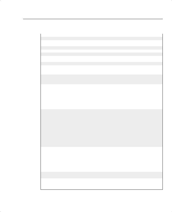
Table 7-9 Queuing Tool Support with FRTS and FRF.12 (Cisco IOS Software Release 12.2 Mainline)
|
Queuing Tools Supported on Each VC |
Desired Features |
(Shaping Queues) |
|
|
FRTS only |
FIFO, PQ, Custom Queuing (CQ), Weighted Fair |
|
Queuing (WFQ), Class-Based Weighted Fair Queuing |
|
(CBWFQ), LLQ, IP RTP Priority |
|
|
FRTS with FRF.12 enabled |
WFQ, CBWFQ, LLQ, IP RTP Priority |
|
|
FRTS, FRF.12, with actual interleaving |
LLQ, IP RTP Priority |
of packets |
|
|
|
Choosing Fragment Sizes for Frame Relay
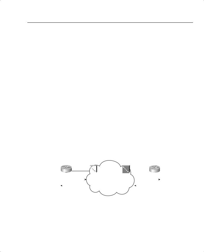
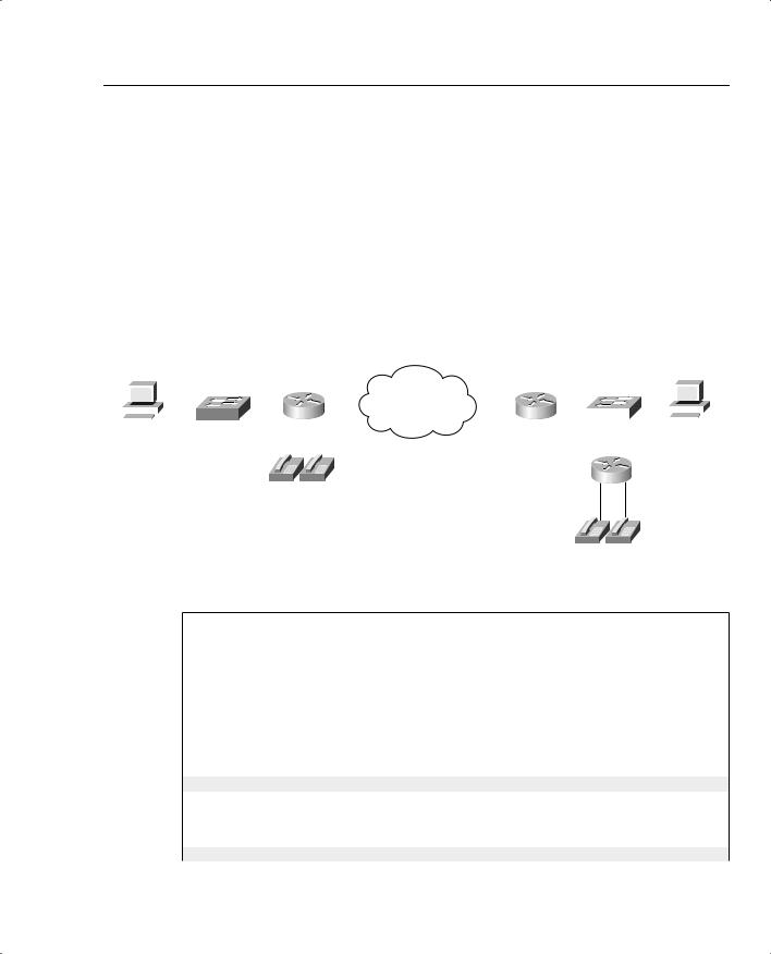
FRF.12 uses the same basic math as does MLP LFI to determine the fragment size—max-delay * bandwidth. But what do you use for bandwidth in the formula? CIR? Do you use the shaping or policing rate? Or the access rate, which is the clock rate used on the access link? Figure 7-11 shows a typical Frame Relay network that provides a backdrop from which to discuss which values to use.
Figure 7-11 Example Frame Relay Network Used to Explain How to Choose Fragment Sizes
|
|
|
|
|
|
|
|
CIR 64 kbps |
|
|
|
|
|
|
|
|
|
|
AR 128 kbps |
|
|
|
|
AR 1544 kbps |
|||||||
|
|
|
|
|
|
||||||||||
|
|
|
|
|
|
|
|
|
|
|
|
|
|
|
|
|
R2 |
|
|
|
|
|
|
|
Main |
||||||
|
|
Frame Relay |
|
|
|
|
|||||||||
|
|
|
|
|
FRS1 |
FRS2 |
|||||||||
|
|
|
|
|
Virtual Circuit |
||||||||||
160 byte frag takes 10ms |
|
|
160 byte frag takes .8ms |
||||||||||||
|
|
|
|
|
|
|
|
|
|
||||||
160 byte frag takes 10ms |
|
|
160 byte frag takes .8ms |
||||||||||||
|
|
|
|
|
|
|
|
|
|
|
|
|
|
|
|
In most cases, you should choose to fragment based on the slower access rate on either end of a VC, which in this case is the 128-kbps access rate on R1. The reason you should use the lower of the two access rates becomes apparent only when you think of serialization delay inside the cloud, and in both directions. First, consider left-to-right flow in the network. To reduce serialization delay to 10 ms on a 128-kbps link, the fragment size should be set to 160 bytes (128,000 * .01 = 1280 bits). When R2 sends a packet, the serialization delay takes 10 ms.
504 Chapter 7: Link-Efficiency Tools
Moving from left to right, a full-sized fragment sent from FRS1 to the Main router takes only 0.8 seconds to serialize! Reversing the direction, a 160-byte fragment leaving router Main, going into the cloud, only takes 0.8-ms serialization delay, so you might be tempted to make the fragment size much larger for packets sent by router Main. When the packets get to FRS2, however, and need to cross the access link to R1, a small fragment size of 160 bytes gives you an advantage of low serialization delay. If you were to make the fragment size on the Main router a much larger size, the frame would experience a much larger serialization delay on the link from FRS1 to R1.
One common misconception is that fragmentation size should be based on the CIR of the VC, rather than on the access rate. Fragmentation attacks the problem of serialization delay, and serialization delay is based on how long it takes to encode the bits onto the physical interface, which in turn is determined by the physical clock rate on the interface. So, you should always base FRF.12 fragmentation sizes on the clock rate (access rate) of the slower of the two access links, not on CIR.
FRF.12 configuration does not let you set the maximum delay, as does MLP LFI. Instead, you configure the fragment size directly. When planning, you normally pick a maximum serialization delay for each link first. So before you can configure FRF.12, you need to calculate the fragmentation size. When you know the lower of the two access rates, and the maximum serialization delay desired, you can calculate the corresponding fragment size with the following formula:
Max-delay * bandwidth
Table 7-8, shown earlier in this section, lists some of the more common combinations of maximum delay and bandwidth, with the resulting fragment sizes.
Fragmentation with More Than One VC on a Single Access Link
Cisco IOS Software enables FRF.12 per VC—in other words, you can perform LFI for the traffic on some VCs, but not others. Therefore, before configuring FRF.12, you should decide which VCs really need to use it.
You first need to determine whether any of the Frame Relay VCs need to use LFI. If the traffic on all the VCs can tolerate the delays without performing LFI, you are better off not fragmenting the frames. Fragmentation does increase the bandwidth required in the network slightly, because the fragmentation headers add a few bytes of overhead. Therefore, if serialization delay is not an issue, do not use FRF.12 at all.
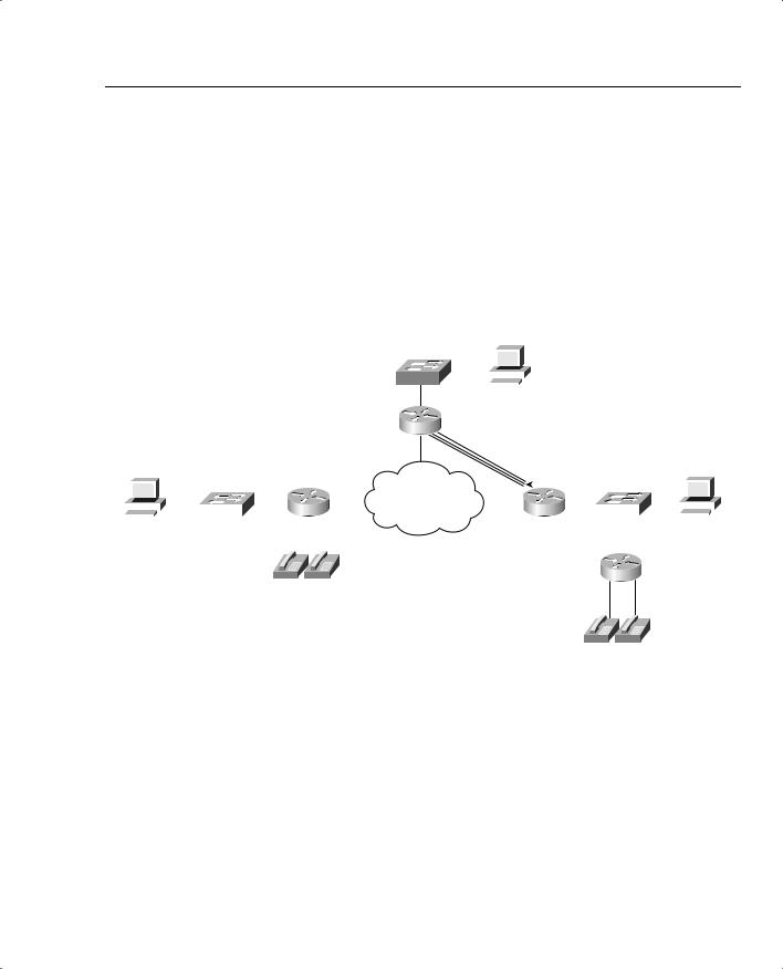
Most installations consider LFI when voice is added to the network. If voice is added to all sites in a Frame Relay network, of course you would consider LFI on all the VCs. The interesting choice comes when you have compelling reasons for LFI on some VCs, and not-so-obvious compelling reasons for others. The network in Figure 7-12 shows just such a network, with voice between the Main site and R1, and no voice to the other two remote sites.

506 Chapter 7: Link-Efficiency Tools
Table 7-10 Comparisons Between MLP LFI and FRF.12
Step in the Process |
MLP LFI |
FRF.12 |
|
|
|
Configures maximum delay, |
Maximum delay |
Fragment size |
or actual fragment size |
|
|
|
|
|
Classification into the |
Based on the queuing tool enabled |
All packets coming from |
interface output queues |
on the interface |
LLQ or RTP Priority shaping |
|
|
queues placed in higher- |
|
|
priority queue |
|
|
|
Number of interface output |
Based on the queuing tool enabled |
2 queues, called Dual FIFO |
queues |
on the interface |
|
|
|
|
How queue service algorithm |
Based on queuing tool’s inherent |
PQ-like algorithm, always |
causes interleaving to occur |
queue service algorithm; PQ, LLQ, |
servicing High queue over |
|
and RTP Priority most aggressively |
Normal queue |
|
interleave packets |
|
|
|
|
Multilink PPP Interleaving Configuration
Before you configure MLP LFI, think about why you would use MLP at all. If you have a point- to-point link, and need to perform LFI, you must migrate from your current Layer 2 protocol to MLP, to use MLP LFI. However, MLP itself has many benefits, and even a few brief thoughts about what MLP does will help you through some of the configuration tasks.
MLP enables you to have multiple parallel point-to-point links between a pair of devices, such as routers. The main motivation for MLP was to allow dial applications to continue adding additional switched WAN connections between the endpoints when more bandwidth was needed. For instance, maybe one dialed line was brought up, but when the utilization exceeded 60 percent, another line dialed, and then another, and so on.
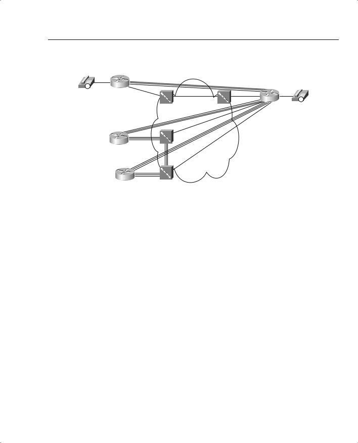
MLP includes the inherent capability to load balance the traffic across the currently active lines, without causing reordering problems. To understand those concepts, consider Figure 7-13, with three parallel point-to-point links controlled by MLP.
Figure 7-13 MLP Bundled with 3 Active Links—What Could Happen
|
|
|
|
|
|
|
1500 |
|
|
|
|
|
|
|
||
|
|
|
|
|
|
|
|
|
|
|
|
|
Reordered packets |
|||
|
|
|
|
|
|
|
|
|
|
|
|
|
||||
|
|
|
|
|
|
|
|
|
|
|
|
|
||||
|
|
|
|
|
|
|
|
|
|
|
|
|
||||
|
|
|
|
|
|
|
|
100 |
|
|
|
|
|
|
|
|
|
|
|
|
|
|
|
|
|
|
|
|
|
|
|
|
|
|
|
|
|
|
R1 |
|
|
|
|
|
|
R2 |
1500 |
|
100 |
|
|
|
|
|
|
|
|
|
|
|
|
||||||
100 |
|
1500 |
|
|
|
|
|
|
|
|||||||
|
|
|
|
|
|
|
|
|
|
|
|
|
|
|
|
|
|
|
|
|
|
|
|
|
|
|
|
|
|
|
|
|
|
Link Fragmentation and Interleaving 507
With three active links, MLP could reorder packets. If a 1500-byte packet arrives, for instance, immediately followed by a 100-byte packet, MLP might send the first packet over one link, and the next packet over the second link. Because the second packet is much smaller, its serialization delay will be much smaller. Assuming that both links speeds are equal, the 100-byte packet will arrive before the larger packet. Consequently, the 100-byte packet is forwarded first, before the 1500-byte packet. If both packets are part of the same flow, the endpoint computer may have to do more work to reorder the packets, which TCP could do if it is being used. However, some UDP-based applications could require that the out-of-order packets be re-sent, depending on the application. Over time, the three links will experience different utilization averages, depending on the random occurrence of traffic in the network.
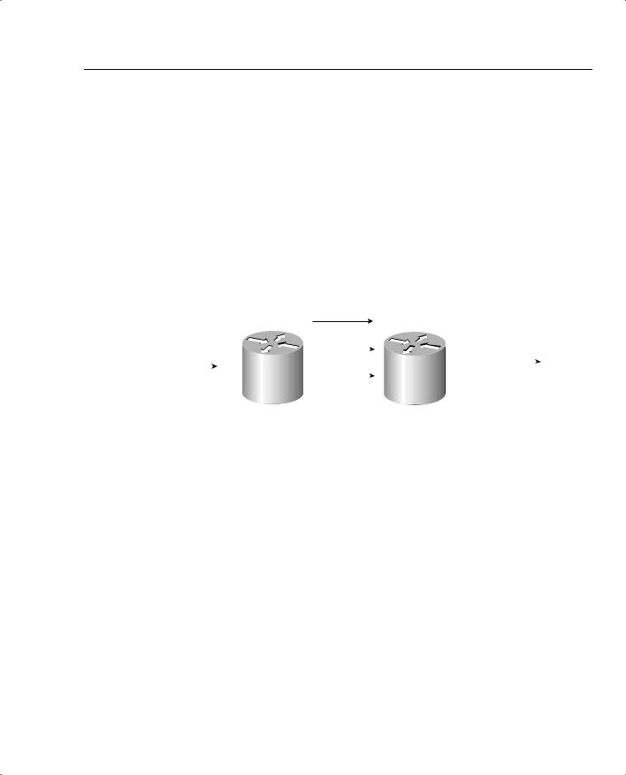
MLP does not behave as shown in Figure 7-13. Instead, MLP, by its very nature, fragments packets. Figure 7-14 shows what really happens.
Figure 7-14 MLP Bundle with 3 Active Links—What Does Happen
|
|
|
|
|
|
|
|
500 (Frag 1) |
|
|
|
|
|
|
|||
|
|
|
|
|
|
|
|
|
|
|
|
|
|
|
|
|
|
|
|
|
|
|
|
|
|
|
|
|
|
|
|
|
|
|
|
|
|
|
|
|
|
|
|
|
|
|
|
|
|
|
|
||
|
|
|
|
|
|
|
|
|
|
|
|
|
|
|
|
|
|
|
|
|
|
|
|
|
|
500 (Frag 2) |
|
|
|
|
|
|
|||
|
|
|
|
|
|
|
|
|
|
|
|
|
|||||
|
|
|
|
|
|
|
|
|
|
|
|
|
|
|
|
|
|
|
|
|
|
|
R1 |
|
|
|
|
|
R2 |
100 |
|
1500 |
|
||
|
|
|
|
|
|
|
|
|
|
||||||||
100 |
|
1500 |
|
|
|
|
|
|
|
|
|||||||
|
|
|
|
|
|
|
|
500 (Frag 3) |
|
|
|
|
|
|
|||
|
|
|
|
|
|
|
|
|
|
|
|
||||||
|
|
|
|
|
|
|
|
|
|
|
|
|
|
|
|
|
|
|
|
|
|
|
|
|
|
|
|
|
|
|
|
|
|
|
|
MLP always fragments PPP frames to load balance traffic equitably and to avoid out-of-order packets. Notice that the 1500-byte packet was fragmented into three 500-byte fragments, one for each link. By default, MLP fragments each packet into equal-sized fragments, one for each link. Suppose, for instance, that two links were active; the fragments would have been 750 bytes long. If four were active, each fragment would have been 375 bytes long. And yes, even the 100-byte packet would be fragmented, with one fragment being sent over each link.
The other point you should consider about basic MLP, before looking at MLP LFI configuration, is that the multiple links appear as one link from a Layer 3 perspective. In the figures, R1 and R2 each have one IP address that applies to all three links. To configure these details, most of the interface subcommands normally entered on the physical interface are configured somewhere else, and then applied to each physical interface that will comprise part of the same MLP bundle.
With those two basic MLP concepts in mind, you can now make more sense of the MLP LFI configuration. Tables 7-11 and 7-12 list the pertinent configuration and show commands, respectively, and are followed by some example configurations.


510 Chapter 7: Link-Efficiency Tools
Example 7-5 MLP LFI Configuration (Continued)
!
!
!STEP 2 STEP 2 STEP 2 STEP 2 STEP 2 STEP 2 STEP 2 STEP 2 STEP 2 STEP 2
!Adding Fragmentation for 10ms fragments. Added same command on R1 as well,
!No shown here for brevity.
!
R3#conf t
Enter configuration commands, one per line. End with CNTL/Z. R3(config)#interface multilink 9
R3(config-if)#ppp multilink fragment-delay 10
R3(config-if)#^Z
R3#show interfaces multilink 9
Multilink9 is up, line protocol is up Hardware is multilink group interface Internet address is 192.168.99.253/24
MTU 1500 bytes, BW 128 Kbit, DLY 100000 usec, reliability 255/255, txload 233/255, rxload 43/255
Encapsulation PPP, loopback not set Keepalive set (10 sec)
DTR is pulsed for 2 seconds on reset LCP Open, multilink Open
Open: IPCP
Last input 00:00:02, output never, output hang never Last clearing of "show interface" counters 00:20:41
Input queue: 0/75/0/0 (size/max/drops/flushes); Total output drops: 1056 Queueing strategy: weighted fair
Output queue: 64/1000/64/1055 (size/max total/threshold/drops) Conversations 5/11/32 (active/max active/max total) Reserved Conversations 0/0 (allocated/max allocated) Available Bandwidth 96 kilobits/sec
30 second input rate 22000 bits/sec, 44 packets/sec
30 second output rate 117000 bits/sec, 48 packets/sec
4459 packets input, 273353 bytes, 0 no buffer Received 0 broadcasts, 0 runts, 0 giants, 0 throttles
0 input errors, 0 CRC, 0 frame, 0 overrun, 0 ignored, 0 abort 62241 packets output, 5141980 bytes, 0 underruns
0 output errors, 0 collisions, 0 interface resets
0 output buffer failures, 0 output buffers swapped out
0 carrier transitions
!
!STEP 3 STEP 3 STEP 3 STEP 3 STEP 3 STEP 3 STEP 3 STEP 3 STEP 3 STEP 3
!Added Interleaving feature. Did same on R1, not shown here.
!
R3#conf t
Enter configuration commands, one per line. End with CNTL/Z. R3(config)#interface multilink 9
R3(config-if)#ppp multilink interleave
R3(config-if)#^Z

512 Chapter 7: Link-Efficiency Tools
Example 7-5 MLP LFI Configuration (Continued)
!
!
!STEP 4 STEP 4 STEP 4 STEP 4 STEP 4 STEP 4 STEP 4 STEP 4 STEP 4 STEP 4
!Adding RTP Priority Queuing configuration next. Did same on R1.
!
R3#conf t
Enter configuration commands, one per line. End with CNTL/Z. R3(config)#interface multilink 9
R3(config-if)#ip rtp priority 16384 16383 65
R3(config-if)#^Z R3#
R3#show interfaces multilink 9
Multilink9 is up, line protocol is up Hardware is multilink group interface Internet address is 192.168.99.253/24
MTU 1500 bytes, BW 128 Kbit, DLY 100000 usec, reliability 255/255, txload 231/255, rxload 41/255
Encapsulation PPP, loopback not set Keepalive set (10 sec)
DTR is pulsed for 2 seconds on reset LCP Open, multilink Open
Open: IPCP
Last input 00:00:03, output never, output hang never Last clearing of "show interface" counters 00:23:36
Input queue: 0/75/0/0 (size/max/drops/flushes); Total output drops: 1784 Queueing strategy: weighted fair
Output queue: 17/1000/64/1783/4441 (size/max total/threshold/drops/interleaves) Conversations 5/11/32 (active/max active/max total)
Reserved Conversations 0/0 (allocated/max allocated) Available Bandwidth 31 kilobits/sec
30 second input rate 21000 bits/sec, 43 packets/sec
30 second output rate 116000 bits/sec, 59 packets/sec
10217 packets input, 618117 bytes, 0 no buffer Received 0 broadcasts, 0 runts, 0 giants, 0 throttles
0 input errors, 0 CRC, 0 frame, 0 overrun, 0 ignored, 0 abort 72195 packets output, 7661717 bytes, 0 underruns
0 output errors, 0 collisions, 0 interface resets
0 output buffer failures, 0 output buffers swapped out
0 carrier transitions
R3#show queue multilink 9
Input queue: 0/75/0/0 (size/max/drops/flushes); Total output drops: 1784 Queueing strategy: weighted fair
Output queue: 18/1000/64/1783/6643 (size/max total/threshold/drops/interleaves) Conversations 6/11/32 (active/max active/max total)
Reserved Conversations 0/0 (allocated/max allocated) Available Bandwidth 31 kilobits/sec
Link Fragmentation and Interleaving 513
Example 7-5 MLP LFI Configuration (Continued)
(depth/weight/total drops/no-buffer drops/interleaves) 1/0/0/0/0 Conversation 40, linktype: ip, length: 62
source: 192.168.3.254, destination: 192.168.99.251, id: 0x08E5, ttl: 253, TOS: 0 prot: 17, source port 18490, destination port 17228
(depth/weight/total drops/no-buffer drops/interleaves) 1/32384/11/0/1282 Conversation 0, linktype: ip, length: 74
source: 192.168.3.100, destination: 192.168.1.100, id: 0xED88, ttl: 127, TOS: 0 prot: 6, source port 80, destination port 1513
!
!Lines omitted for brevity
!STEP 5 STEP 5 STEP 5 STEP 5 STEP 5 STEP 5 STEP 5 STEP 5 STEP 5 STEP 5
R3#show running-config
!Lines omitted for brevity
!
username R1 password 0 me
!
interface Multilink9 bandwidth 128
ip address 192.168.99.253 255.255.255.0 no ip route-cache cef
load-interval 30 fair-queue
no cdp enable ppp multilink
ppp multilink fragment-delay 10 ppp multilink interleave multilink-group 9
ip rtp priority 16384 16383 65
!
interface Serial0/1 bandwidth 128
no ip address encapsulation ppp no ip mroute-cache load-interval 30 clockrate 128000 ppp multilink multilink-group 9
!
! Lines omitted for brevity
!

Link Fragmentation and Interleaving 515
interleave the shorter, unfragmented frames. Remember, however, that MLP fragments frames to load balance across multiple links without running into the problems relating to out-of-order packets.
Step 3 To gain the QoS advantage of reducing serialization delay by interleaving packets, the ppp multilink interleave command is added to the configuration next. The show interfaces command that follows lists a (highlighted) line that now shows a counter for interleaved packets, with the counter indeed showing that some packets have been interleaved.
Now the example has added all the requirements for MLP LFI, and all seems well—but it is not! The voice quality is still barely tolerable, with long delay and many breaks in the speech. The voice quality still suffers because of the queuing tool, WFQ. Notice that the next command in the example, show queue multilink 9, lists a voice flow with some statistics highlighted for the voice flow. The command lists drops for the highlighted voice flow, which is making a large impact of voice quality. Although the voice packets that get serviced do get interleaved, causing the interleave counter in the show interfaces command to increment, the quality still suffers because of the queuing delay and drops.
Step 4 The best ways to prevent the drops is to enable Low Latency Queuing (LLQ) for the voice traffic. Just to have another example of IP RTP Priority for practice, I chose to use the IP RTP Priority feature, enabling it with the ip rtp priority 65 command. However, LLQ is still recommended today for voice traffic. After adding the ip rtp priority command, the show interfaces command still shows interleaves, which is good, but the show queue command does not show any drops for the voice flow. In fact, the voice-call quality improved significantly to the point that all New Jersey housewives would give the call a Mean Opinion Score of 5!
Step 5 The final configuration on R3 is listed at the end of the example for completeness.
Frame Relay Fragmentation Configuration
The configuration of FRF.12 requires very little effort in itself. However, FRF.12 requires FRTS, and for the FRF.12 interleaving function to actually work, you need to enable IP RTP Priority or LLQ for the shaping queues on one or more VCs. Therefore, although the FRF.12 new configuration details are brief, the related tools make the configuration a little longer.

516 Chapter 7: Link-Efficiency Tools
The show commands related to FRF.12 give a fairly detailed view into what is actually happening with fragmentation and are covered as part of a couple of examples. Tables 7-13 and 7-14 list the configuration and show commands, respectively, and are followed by two FRF.12 examples.
Table 7-13 Command Reference for Frame Relay Fragmentation
|
Command |
Mode and Function |
|
|
|
|
frame-relay traffic-shaping |
Interface subcommand; enables FRTS on the |
|
|
interface |
|
|
|
|
class name |
Interface DLCI subcommand; enables a specific |
|
|
FRTS map class for the DLCI |
|
|
|
|
frame-relay class name |
Interface or subinterface command; enables a |
|
|
specific FRTS map class for the interface or |
|
|
subinterface |
|
|
|
|
map-class frame-relay map-class-name |
Global configuration mode; Names a map class, and |
|
|
places user in map-class configuration mode. |
|
|
|
|
frame-relay fragment fragment_size |
Map-class configuration mode; enables FRF.12 for |
|
|
VCs using this class |
|
|
|
Table 7-14 Exec Command Reference for Frame Relay Fragmentation |
||
|
|
|
|
Command |
Function |
|
|
|
|
show frame-relay fragment [interface |
Shows fragmentation statistics |
|
interface] [dlci] |
|
|
|
|
|
show frame-relay pvc [interface-type |
Shows statistics about overall performance of a VC |
|
interface-number] [dlci] |
|
|
|
|
|
show queueing [interface atm-subinterface |
Lists configuration and statistical information about |
|
[vc [[vpi/] vci]]] |
the queuing tool on an interface |
|
|
|
The FRF.12 sample configuration that follows uses the same FRTS configuration details as one of the FRTS examples from Chapter 5, but with the FRF.12 configuration added. The criteria for the configuration is as follows:
•Clock rate is 128 kbps on the access links on each end of the VC between R3 and R1.
•Fragment to 10-ms fragments.
•Shape all traffic at a 64-kbps rate.
•Configure Tc for 10ms.
518 Chapter 7: Link-Efficiency Tools
Example 7-6 FRF.12 Configuration Sample (Continued)
frame-relay interface-dlci 101 IETF
!
interface Serial0/0.2 point-to-point
description point-to-point subint connected to DLCI 102 (R2) ip address 192.168.23.253 255.255.255.0
frame-relay interface-dlci 102
!
!
! Many lines omitted for brevity
!
map-class frame-relay shape-all-64 frame-relay traffic-rate 64000 640 no frame-relay adaptive-shaping frame-relay fair-queue
frame-relay fragment 160
! |
|
|
|
|
|
|
|
|
|
|
R3#show frame-relay fragment interface s 0/0.1 101 |
|
|
|
|
|
|||||
fragment size 160 |
|
|
|
fragment type end-to-end |
|
|
||||
|
|
|
|
|
|
|
|
|||
in fragmented pkts 52 |
|
|
out fragmented pkts 9367 |
|
|
|||||
in fragmented bytes 5268 |
|
out fragmented bytes 1511866 |
|
|
||||||
in un-fragmented pkts 5552 |
|
out un-fragmented pkts 6320 |
|
|
|
|
||||
in un-fragmented bytes 341743 |
|
|
|
|
|
|
||||
|
out un-fragmented bytes 405268 |
|
|
|||||||
in assembled pkts 5577 |
|
|
out pre-fragmented pkts 7387 |
|
|
|
||||
in assembled bytes 346749 |
|
|
|
|
||||||
|
out pre-fragmented bytes 1862784 |
|
||||||||
in dropped reassembling pkts 0 |
|
out dropped fragmenting pkts 0 |
|
|
||||||
in timeouts 0 |
|
|
|
|
|
|
|
|
|
|
in out-of-sequence fragments 0 |
|
|
|
|
|
|
|
|
||
in fragments with unexpected B bit set 0 |
|
|
|
|
|
|
||||
in fragments with skipped sequence number 0 |
|
|
|
|
|
|
||||
out interleaved packets 0 |
|
|
|
|
|
|
|
|
||
R3#show frame-relay fragment |
|
|
|
|
|
|
|
|
||
interface |
dlci |
frag-type |
frag-size |
in-frag |
out-frag |
dropped-fr |
||||
ag |
|
|
|
|
|
|
|
|
|
|
|
|
|
|
|
|
|
|
|
|
|
Serial0/0.1 |
101 |
end-to-end |
160 |
|
54 |
9700 |
|
|
0 |
|
|
|
|
|
|
|
|
|
|
|
|
R3#show frame-relay pvc
PVC Statistics for interface Serial0/0 (Frame Relay DTE)
|
Active |
Inactive |
Deleted |
Static |
Local |
2 |
0 |
0 |
0 |
Switched |
0 |
0 |
0 |
0 |
Unused |
0 |
0 |
0 |
0 |
DLCI = 101, DLCI USAGE = LOCAL, PVC STATUS = ACTIVE, INTERFACE = Serial0/0.1
input pkts 6094 |
output pkts 7926 |
in |
bytes 379217 |
out bytes 1998660 |
dropped pkts 0 |
in |
FECN pkts 0 |
in BECN pkts 0 |
out FECN pkts 0 |
out BECN pkts 0 |
|

|
|
|
|
|
Link Fragmentation and Interleaving 519 |
|
|
|
|
|
|||
Example 7-6 FRF.12 Configuration Sample (Continued) |
|
|
||||
|
in DE pkts 0 |
|
out DE pkts 0 |
|
||
|
|
|
||||
|
out bcast pkts 31 |
out bcast bytes 2416 |
|
|||
|
pvc create time 00:25:19, last time pvc status changed 00:15:50 |
|
||||
|
R3#show interface s 0/0 |
|
|
|
||
|
Serial0/0 is up, line protocol is up |
|
|
|||
|
Hardware is PowerQUICC Serial |
|
|
|||
|
Description: connected to FRS port S0. Single PVC to R1. |
|
||||
|
MTU 1500 bytes, BW 1544 Kbit, DLY 20000 usec, |
|
||||
|
reliability 255/255, txload 20/255, rxload 4/255 |
|
||||
|
Encapsulation FRAME-RELAY, loopback not set |
|
||||
|
Keepalive set |
(10 sec) |
|
|
|
|
|
LMI enq sent |
14, LMI stat recvd 14, LMI upd recvd 0, DTE LMI up |
|
|||
|
LMI enq recvd 0, LMI stat sent 0, LMI upd sent 0 |
|
||||
|
LMI DLCI 1023 |
LMI type is CISCO |
frame relay DTE |
|
||
|
Broadcast queue 0/64, broadcasts sent/dropped 65/0, interface broadcasts 61 |
|
||||
|
Last input 00:00:03, output 00:00:00, output hang never |
|
||||
|
Last clearing of "show interface" counters 00:02:20 |
|
||||
|
|
|
|
|||
|
Queueing strategy: dual fifo |
|
|
|||
|
Output queue: high size/max/dropped 0/256/0 |
|
||||
|
Output queue 77/128, 176 drops; input queue 0/75, 0 drops |
|
||||
|
30 second input rate 26000 bits/sec, 51 packets/sec |
|
||||
|
30 second output rate 122000 bits/sec, 126 packets/sec |
|
||||
|
6599 packets input, 409250 bytes, 0 no buffer |
|
||||
|
Received 0 broadcasts, 0 runts, 0 giants, 0 throttles |
|
||||
|
0 input errors, 0 CRC, 0 frame, 0 overrun, 0 ignored, 0 abort |
|
||||
|
17824 packets output, 2169926 bytes, 0 underruns |
|
||||
|
0 output errors, 0 collisions, 0 interface resets |
|
||||
|
0 output buffer failures, 0 output buffers swapped out |
|
||||
|
0 carrier transitions |
|
|
|
||
|
DCD=up |
DSR=up DTR=up |
RTS=up |
CTS=up |
|
|
|
R3#show queueing interface s 0/0 |
|
|
|||
|
|
|
||||
|
Interface Serial0/1 queueing strategy: priority |
|||||
|
|
|
||||
|
Output queue utilization (queue/count) |
|||||
|
high/0 medium/0 normal/16513 low/0 |
|
||||
|
! |
|
|
|
|
|
|
! Many lines |
omitted for brevity |
|
|
||
|
! |
|
|
|
|
|
|
|
|
|
|
|
|
Take a look at the highlighted configuration at the beginning of the example. FRF is configured with the frame-relay fragment command inside a map-class command. In this case, the fragment size was set to 160 bytes, which at a clock rate of 128 kbps implies 10 ms of serialization delay for the longest frame. The rest of the configuration enables FRTS on serial 0/0.1, which enables fragmentation, because the frame-relay fragment 160 command sits inside map-class frame-relay shape-all-64. To review, FRTS is enabled for all VCs on interface s0/0 by the frame-relay traffic-shaping command on the physical interface. To use the specific

Link Fragmentation and Interleaving 521
Tc value, to reduce the delay waiting for the next shaping interval. The next example uses a class map called shape-all-96-shortTC, which includes FRF.12, LLQ, with shaping using a 10-ms Tc.
This next example also oversubscribes the access link from R3 to the FR cloud. When supporting voice, Cisco recommends to not oversubscribe an access link. However, many data-oriented Frame Relay designs purposefully oversubscribe the access links. Therefore, when the time comes to add VoIP traffic, increasing the CIRs on all the VCs may not be financially possible. This example uses two VCs, with each shaped at 96 kbps, with a 128-kbps access rate. Figure 7-17 outlines the network.
Figure 7-17 Frame Relay Network with the R3 Access Link Oversubscribed
|
|
|
|
|
|
|
|
|
|
|
|
|
|
|
|
|
|
|
|
|
|
|
|
|
Client2 |
|
|
|
|
|
|
|
|
|
|
|
|
|
|
|
|
|
|
|
|
|
|
|
|
|
|
|
|
|
|
|
|
|
|
|
|
|
|
|
|
|
|
|
|
|
|
|
|
|
|
|
|
|
|
|
|
|
|
|
SW1 |
|
|
|
|
|
|
|
|
|
|
|
|
|
|
|
|
|
|
|
|
|
|
|
|
|
|
|
|
|
|
|
|
|
|
|
|
|
|
|
|
|
|
|
|
|
|
|
|
|
|
|
|
||
|
|
|
|
|
|
|
|
|
|
|
|
|
|
|
|
|
|
|
|
|
|
|
|
|
|
|
|
|||||||
|
|
|
|
|
|
|
|
|
|
|
|
|
|
|
R1 |
|
128-kbps Access Rate |
|
|
|
|
|
|
|
|
|||||||||
Note: All IP Addresses Begin 192.168. |
|
Each VC Shaped at 96 kbps |
|
|
|
|
|
|
|
|||||||||||||||||||||||||
|
|
|
|
|||||||||||||||||||||||||||||||
Client1 |
2.252 |
|
|
|
|
|
|
|
|
|
|
|
|
|
|
|
Server1 |
|||||||||||||||||
|
|
|
|
|
|
|
|
|
|
|
|
|
|
|
|
|
|
|
|
|
|
|
|
|
|
|
||||||||
|
|
|
|
|
|
|
1.252 |
|
|
|
|
|
|
|
|
|
|
|
|
|
|
|
|
|
|
|
|
|
|
|
|
|
|
|
|
|
|
|
|
|
|
|
|
|
|
|
|
|
|
|
|
|
|
|
|
|
|
|
|
|
|
|
|
|
|
|
|
|
|
|
|
|
|
|
|
|
|
|
|
|
|
|
|
|
|
|
|
|
|
|
|
|
|
|
|
|
|
|
|
|
|
|
|
|
|
|
|
|
|
|
SW1 |
|
|
|
R1 |
|
s0/0 |
|
|
|
s0/0 R3 |
SW2 |
|
|
|
|
|
|
|||||||||||
|
|
|
|
|
|
|
|
|
|
|
|
|
|
|
|
|||||||||||||||||||
1.100 |
|
|
|
|
|
|
|
|
|
|
|
|
|
|
|
|
|
|
|
|
|
|
|
|
3.100 |
|
|
|||||||
|
|
|
|
|
|
|
|
|
|
|
|
|
|
|
|
|
|
|
|
|
|
|
|
|
|
|
|
3.254 |
|
|
|
|
|
|
|
|
|
|
|
|
|
|
|
|
|
|
|
|
|
|
|
|
|
|
|
|
|
|
|
|
|
|
|
|
|
|
|
|
|
|
|
|
|
|
|
|
|
|
|
|
|
|
|
|
|
|
|
|
|
|
|
|
|
|
|
|
|
|
|
|
|
|
|
|
|
|
|
|
|
|
|
|
|
|
|
|
|
|
|
|
|
|
|
|
|
|
|
|
|
|
|
|
|
|
|
|
|
|
|
R4
1001 1002
3001 3002
The criteria for the example is as follows:
•Clock rate is 128 kbps on all access links.
•Fragment to 10-ms fragments.
•Shape all VCs at a 96-kbps rate.
•Set Tc to 10 ms.
•Do not use a Be.
•Configure LLQ, with VoIP in the low-latency queue, and all other traffic in another queue.

522 Chapter 7: Link-Efficiency Tools
In the example, Client 1 and Client 2 each download one web page, which has two frames inside the page. Each page download uses two separate TCP connections to download two separate large JPG files. Both PCs also download a file using FTP get. In addition, a VoIP call is placed between extensions 3002 and 1002. Figure 7-17 depicts the network used in the example. Example 7-7 shows the configuration and some sample show commands.
Example 7-7 Oversubscribed Access Link, with FRF.12, LLQ, and Tc = 10 ms
R3#show running-config
!
! Portions omitted for brevity
!
class-map match-all voip-rtp match ip rtp 16384 16383
!
!
policy-map voip-and-allelse class voip-rtp
priority 30
class class-default fair-queue
!
interface Serial0/0
description connected to FRS port S0. Single PVC to R1. no ip address
encapsulation frame-relay load-interval 30 clockrate 128000 bandwidth 128
frame-relay traffic-shaping
!
interface Serial0/0.1 point-to-point
description point-point subint global DLCI 103, connected via PVC to DLCI 101 ( ip address 192.168.2.253 255.255.255.0
frame-relay class shape-all-96-shortTC frame-relay interface-dlci 101 IETF
!
interface Serial0/0.2 point-to-point
description point-to-point subint connected to DLCI 102 (R2) ip address 192.168.23.253 255.255.255.0
frame-relay class shape-all-96-shortTC frame-relay interface-dlci 102
!
map-class frame-relay shape-all-96-shortTC no frame-relay adaptive-shaping frame-relay cir 96000
frame-relay bc 960
service-policy output voip-and-allelse frame-relay fragment 160
!

524 Chapter 7: Link-Efficiency Tools
Example 7-7 Oversubscribed Access Link, with FRF.12, LLQ, and Tc = 10 ms (Continued)
Class-map: voip-rtp (match-all) 0 packets, 0 bytes
30 second offered rate 0 bps, drop rate 0 bps Match: ip rtp 16384 16383
Weighted Fair Queueing Strict Priority
Output Queue: Conversation 24 Bandwidth 30 (kbps) Burst 750 (Bytes) (pkts matched/bytes matched) 0/0 (total drops/bytes drops) 0/0
Class-map: class-default (match-any) 1440 packets, 1275806 bytes
30 second offered rate 55000 bps, drop rate 0 bps Match: any
R3#show queueing interface serial 0/0
Interface Serial0/0 queueing strategy: priority
Output queue utilization (queue/count) high/9514 medium/0 normal/34038 low/0
The FRF.12 configuration portion of the example is comprised again of a single command, frame-relay fragment 160, configured inside map-class frame-relay shape-all-96-shortTC. The rest of the configuration meets the other requirements stated before the example. The map class includes a setting of CIR to 96,000 bps, and a Bc of 960 bits, yielding a Tc value of 960/96,000, or 10 ms. The policy-map voip-and-allelse command defines LLQ for VoIP, with all other traffic being placed in the class-default queue. The service-policy output voip-and- allelse command under class-map frame-relay shape-all-96-shortTC enables LLQ for all VCs that use the class. FRTS is of course enabled on the physical interface, with the framerelay class shape-all-96-shortTC subinterface command causing each of the two VCs to use the FRTS parameters in the map class, rather than the FRTS defaults.
Immediately following the configuration in the example, two show frame-relay traffic-shaping commands verify the settings made in the configuration. Both show a calculated Tc value of 10 ms, and a Bc of 960.
Next comes a pair of show frame-relay fragment interface commands, one for subinterface s 0/0.1, and one for serial interface 0/0.2. On serial 0/0.1, the last line of output points out that interleaves did occur. For interleaves to occur, at least a small amount of congestion must occur on the physical interface. With two VCs shaped at 96 kbps, and a 128-kbps access link, and plenty of generated traffic, some congestion did occur. Notice however that serial 0/0.2 does not show any interleaved packets. All the traffic generated going from R3 to R2 was FTP and HTTP traffic, neither of which gets classified into the low-latency queue. In the show policy-map interface serial 0/0.2 command that ends the example, for instance, notice that the counters