


338 Chapter 5: Traffic Policing and Shaping
explicit congestion notification (FECN) and BECN bits—however, in some networks, the Frame Relay switches do set the bits, and in some, they do not.
If the BECN bit is set, the Main router, if using adaptive shaping, reduces its shaping rate on the VC to R1. Because the congestion occurs right to left, as signaled by a BECN flowing left to right, router Main knows it can slow down and help reduce the congestion. If Main receives another frame with BECN set, Main slows down more. Eventually, Main slows down the shaping rate until it reaches a minimum rate, sometimes called the minimum information rate (MIR), and other times called the mincir.
Similarly, if Main receives a Frame from R12 with FECN set, the congestion is occurring left to right. It does not help for Main to slow down. It does help for R12 to slow down. Therefore, the Main router can “reflect” the FECN, by marking the BECN bit in the next frame it sends on the VC to R12. R12, receiving a BECN, can reduce the shaping rate.
Finally, Foresight messages are separate, nondata signaling frames. Therefore, when the congestion occurs, Foresight does not need to wait on a data frame to signal congestion. In addition, Foresight sends messages toward the device that needs to slow down. For instance, a switch notices congestion right to left on the VC between Main and R24. The switch generates and sends a Foresight message to Main, using that same VC, so Main knows it needs to slow down its shaping rate on that VC temporarily.
When configuring adaptive shaping, you configure the minimum and maximum shaping rate. The configuration commands refer to the minimum rate as mincir, and the maximum rate as CIR, with mincir defaulting to 50 percent of CIR.
With no congestion, shaping uses the maximum rate. When the shaper receives a BECN or Foresight message, it slows down by 25 percent of the maximum rate. It continues to slow down by 25 percent of the maximum rate per Tc, until the minimum rate is reached. After 16 consecutive intervals occur without a BECN or Foresight congestion message, the shaping rate grows by 1/16 of the maximum rate during each Tc, until the maximum rate is reached again.
Where to Shape: Interfaces, Subinterfaces, and VCs
Shaping can be applied to the physical interface, a subinterface, or in some cases, to an individual VC. Depending on the choice, the configuration causes traffic shaping to occur separately for each VC, or it shapes several VCs together. In most cases, engineers want to shape each VC individually.
When shaping is applied to an interface for which VCs do not exist, shaping is applied to the main interface, because there are no subinterfaces or VCs on those interfaces. On Frame Relay and ATM interfaces, however, some sites have multiple VCs terminating in them, which means that subinterfaces will most likely be used. In some cases, more than one VC is associated with

Traffic-Policing and Traffic-Shaping Concepts 339
a single multipoint subinterface; in other cases, point-to-point subinterfaces are used, with a single VC associated with the subinterface. The question becomes this: To shape per VC, where do you enable traffic shaping?
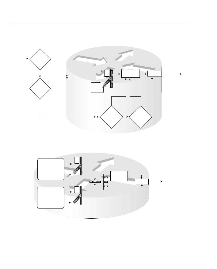
First, consider a typical branch office, such as R24 in Figure 5-10.
Figure 5-10 PB Tents Network: Shaping on Subinterfaces and VCs
R1 |
|
|
|
|
|
|
|
|||
|
|
|
AR 128 kbps |
All VCs 64 kbps CIR |
|
|
||||
|
|
|
|
|||||||
R2 |
|
|
|
|
|
|||||
|
|
|
AR 128 kbps |
|
|
|
|
|
|
Main |
|
|
|
|
|
|
|
|
|
||
|
|
|
|
|
|
|
|
|
|
|
AR 128 kbps |
FRS1 |
FRS2 |
|
AR 1.5 Mbps |
||||||
|
|
|||||||||
|
|
|||||||||
.R3 |
|
|
|
FRS3 |
|
|
||||
|
|
|
|
|
||||||
. AR 128 kbps |
|
|
|
|
|
|
|
|||
|
|
|
|
|
|
|
||||
. |
|
|
|
|
|
|
|
|
|
|
R24
R24 has a single VC to the Main site at PB Tents. Because R24 only has the single VC, the configuration on R24 may not even use subinterfaces at all. If the configuration does not use subinterfaces on R24’s serial link, traffic shaping can be configured on the physical interface. If the configuration includes a subinterface, you can enable traffic shaping on the physical interface, or on the subinterface. Because there is only one VC, it does not really matter whether shaping is enabled on the physical interface, or the subinterface—the behavior is the same.
Now consider the Main router. It has a VC to each remote site. (Also notice that a VC has been added between R1 and R2, just to make things interesting.) So, on the main router, point-to- point subinterfaces are used for the VCs to branches 3 through 24, and a multipoint subinterface is used for the two VCs to R1 and R2. To shape each VC to branches 3 through 24 separately, shaping can be configured on the subinterface. However, shaping applied to a multipoint subinterface shapes all the traffic on all VCs associated with the subinterface. To perform shaping on each VC, you need to enable shaping on each individual data-link connection identifier (DLCI).
In summary, most QoS policies call for shaping on each VC. The configuration commands used to enable shaping differ slightly based on the number of VCs, and how they are configured. Table 5-4 summarizes the options.

340 Chapter 5: Traffic Policing and Shaping
Table 5-4 |
Options of How to Enable Shaping for per-VC Shaping |
|
|
|
|
|
Location |
Requirements for Shaping per VC |
|
|
|
|
No VCs, for example, point-to-point |
Shape on the main interface. Shaping occurs for all traffic |
|
links |
on interface. |
|
|
|
|
Physical interface, 1 VC, no |
Shaping shapes the individual VC associated with this |
|
subinterfaces |
interface. Shaping can be enabled on the physical interface. |
|
|
|
|
Physical interface, 1 VC, 1 subinterface |
Shaping shapes the individual VC associated with this |
|
|
interface. Shaping can be enabled on the physical interface, |
|
|
the subinterface, or the VC (DLCI). |
|
|
|
|
Multiple VCs on 1 interface, point-to- |
Shaping can be enabled on the subinterface, or per DLCI. |
|
point subinterfaces only |
Both methods work identically. |
|
|
|
|
Multiple VCs on 1 interface, some |
Must enable shaping on each DLCI to shape per VC. |
|
multipoint subinterfaces with > 1 VC |
|
|
per subinterface |
|
|
|
|
Queuing and Traffic Shaping
Shaping tools support a variety of queuing tools that can be applied to the packets waiting in the shaping queue(s). At the same time, IOS supports queuing tools for the interface output queue(s) associated with the physical interface. Deciding when to use queuing tools on shaping queues, when to use them on the interface, and how the configurations differ in each case, can be a little confusing. This section clears up some of that confusion.
To begin, Table 5-5 lists the traffic-shaping tools, and the queuing tools supported by each for the shaping queues.
Table 5-5 Options for Queuing in Traffic-Shaping Tools
Shaping Tool |
Queuing Tools Supported for the Shaping Queue(s) |
|
|
GTS |
WFQ |
|
|
CB shaping |
FIFO, WFQ, CBWFQ, LLQ |
|
|
DTS |
FIFO, WFQ, CBWFQ, LLQ |
|
|
FRTS |
FIFO, WFQ, CBWFQ, LLQ, PQ, CQ |
|
|
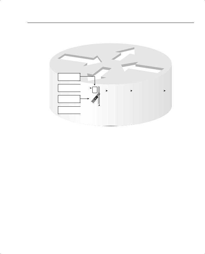
When a shaper uses a queuing tool, instead of having a single shaping queue, multiple shaping queues exist. If FRTS were configured to use Priority Queuing (PQ), for instance, PQ would create four queues for shaping, named High, Medium, Normal, and Low. Figure 5-11 shows the basic idea, with shaping enabled on the physical interface, FIFO Queuing on the physical interface, and PQ configured for shaping the only VC.
 96 kbps