

- •XST User Guide
- •Table of Contents
- •About the XST User Guide
- •XST User Guide Contents
- •Additional Resources
- •Conventions
- •Typographical
- •Online Document
- •1 Introduction to the XST User Guide
- •About XST
- •What’s New in Release 10.1
- •Macro Inference
- •Constraints
- •Libraries Support
- •Setting XST Options
- •2 XST HDL Coding Techniques
- •Signed and Unsigned Support in XST
- •Registers HDL Coding Techniques
- •About Registers
- •Registers Log File
- •Registers Related Constraints
- •Registers Coding Examples
- •Latches HDL Coding Techniques
- •About Latches
- •Latches Log File
- •Latches Related Constraints
- •Latches Coding Examples
- •Tristates HDL Coding Techniques
- •About Tristates
- •Tristates Log File
- •Tristates Related Constraints
- •Tristates Coding Examples
- •Counters HDL Coding Techniques
- •About Counters
- •Counters Log File
- •Counters Related Constraints
- •Counters Coding Examples
- •Accumulators HDL Coding Techniques
- •About Accumulators
- •Accumulators in Virtex-4 and Virtex-5 Devices
- •Accumulators Log File
- •Accumulators Related Constraints
- •Accumulators Coding Examples
- •Shift Registers HDL Coding Techniques
- •About Shift Registers
- •Describing Shift Registers
- •Implementing Shift Registers
- •Shift Registers Log File
- •Shift Registers Related Constraints
- •Shift Registers Coding Examples
- •Dynamic Shift Registers HDL Coding Techniques
- •About Dynamic Shift Registers
- •Dynamic Shift Registers Log File
- •Dynamic Shift Registers Related Constraints
- •Dynamic Shift Registers Coding Examples
- •Multiplexers HDL Coding Techniques
- •About Multiplexers
- •Multiplexers Case Statements
- •Multiplexers Log File
- •Multiplexers Related Constraints
- •Multiplexers Coding Examples
- •Decoders HDL Coding Techniques
- •About Decoders
- •Decoders Log File
- •Decoders Related Constraints
- •Decoders Coding Examples
- •Priority Encoders HDL Coding Techniques
- •About Priority Encoders
- •Priority Encoders Log File
- •Priority Encoders Related Constraints
- •Priority Encoders Coding Examples
- •Logical Shifters HDL Coding Techniques
- •About Logical Shifters
- •Logical Shifters Log File
- •Logical Shifters Related Constraints
- •Logical Shifters Coding Examples
- •Arithmetic Operators HDL Coding Techniques
- •About Arithmetic Operators
- •Arithmetic Operators Log File
- •Arithmetic Operators Related Constraints
- •Arithmetic Operators Coding Examples
- •About Adders, Subtractors, and Adders/Subtractors
- •Adders, Subtractors, and Adders/Subtractors Log File
- •Adders, Subtractors, and Adders/Subtractors Related Constraints
- •Adders, Subtractors, and Adders/Subtractors Coding Examples
- •Comparators HDL Coding Techniques
- •About Comparators
- •Comparators Log File
- •Comparators Related Constraints
- •Comparators Coding Examples
- •Multipliers HDL Coding Techniques
- •About Multipliers
- •Large Multipliers Using Block Multipliers
- •Registered Multipliers
- •Multipliers (Virtex-4, Virtex-5, and Spartan-3A D Devices)
- •Multiplication with Constant
- •Multipliers Log File
- •Multipliers Related Constraints
- •Multipliers Coding Examples
- •Sequential Complex Multipliers HDL Coding Techniques
- •About Sequential Complex Multipliers
- •Sequential Complex Multipliers Log File
- •Sequential Complex Multipliers Related Constraints
- •Sequential Complex Multipliers Coding Examples
- •Pipelined Multipliers HDL Coding Techniques
- •About Pipelined Multipliers
- •Pipelined Multipliers Log File
- •Pipelined Multipliers Related Constraints
- •Pipelined Multipliers Coding Examples
- •Multiply Adder/Subtractors HDL Coding Techniques
- •About Multiply Adder/Subtractors
- •Multiply Adder/Subtractors in Virtex-4 and Virtex- 5 Devices
- •Multiply Adder/Subtractors Log File
- •Multiply Adder/Subtractors Related Constraints
- •Multiply Adder/Subtractors Coding Examples
- •Multiply Accumulate HDL Coding Techniques
- •About Multiply Accumulate
- •Multiply Accumulate in Virtex-4 and Virtex-5 Devices
- •Multiply Accumulate Log File
- •Multiply Accumulate Related Constraints
- •Multiply Accumulate Coding Examples
- •Dividers HDL Coding Techniques
- •About Dividers
- •Dividers Log File
- •Dividers Related Constraints
- •Dividers Coding Examples
- •Resource Sharing HDL Coding Techniques
- •About Resource Sharing
- •Resource Sharing Log File
- •Resource Sharing Related Constraints
- •Resource Sharing Coding Examples
- •RAMs and ROMs HDL Coding Techniques
- •About RAMs and ROMs
- •RAMs and ROMs Log File
- •RAMs and ROMs Related Constraints
- •RAMs and ROMs Coding Examples
- •Initializing RAM Coding Examples
- •ROMs Using Block RAM Resources HDL Coding Techniques
- •About ROMs Using Block RAM Resources
- •ROMs Using Block RAM Resources Log File
- •ROMs Using Block RAM Resources Related Constraints
- •ROMs Using Block RAM Resources Coding Examples
- •Pipelined Distributed RAM HDL Coding Techniques
- •About Pipelined Distributed RAM
- •Pipelined Distributed RAM Log File
- •Pipelined Distributed RAM Related Constraints
- •Pipelined Distributed RAM Coding Examples
- •Finite State Machines (FSMs) HDL Coding Techniques
- •About Finite State Machines (FSMs)
- •Describing Finite State Machines (FSMs)
- •State Encoding Techniques
- •RAM-Based FSM Synthesis
- •Safe FSM Implementation
- •Finite State Machines Log File
- •Finite State Machines Related Constraints
- •Finite State Machines Coding Examples
- •Black Boxes HDL Coding Techniques
- •About Black Boxes
- •Black Box Log File
- •Black Box Related Constraints
- •Black Box Coding Examples
- •3 XST FPGA Optimization
- •About XST FPGA Optimization
- •Virtex-Specific Synthesis Options
- •Macro Generation
- •Virtex Macro Generator
- •Arithmetic Functions in Macro Generation
- •Loadable Functions in Macro Generation
- •Multiplexers in Macro Generation
- •Priority Encoders in Macro Generation
- •Decoders in Macro Generation
- •Shift Registers in Macro Generation
- •RAMs in Macro Generation
- •ROMs in Macro Generation
- •DSP48 Block Resources
- •Mapping Logic Onto Block RAM
- •About Mapping Logic Onto Block RAM
- •Mapping Logic Onto Block RAM Log Files
- •Mapping Logic Onto Block RAM Coding Examples
- •Flip-Flop Retiming
- •About Flip-Flop Retiming
- •Limitations of Flip-Flop Retiming
- •Controlling Flip-Flop Retiming
- •Partitions
- •Incremental Synthesis
- •About Incremental Synthesis
- •Incremental Synthesis (INCREMENTAL_SYNTHESIS)
- •Grouping Through Incremental Synthesis Diagram
- •Resynthesize (RESYNTHESIZE)
- •Speed Optimization Under Area Constraint
- •About Speed Optimization Under Area Constraint
- •Speed Optimization Under Area Constraint Examples
- •FPGA Optimization Log File
- •Design Optimization Report
- •Cell Usage Report
- •Timing Report
- •Implementation Constraints
- •Virtex Primitive Support
- •Instantiating Virtex Primitives
- •Generating Primitives Through Attributes
- •Primitives and Black Boxes
- •VHDL and Verilog Virtex Libraries
- •Virtex Primitives Log File
- •Virtex Primitives Related Constraints
- •Virtex Primitives Coding Examples
- •Using the UNIMACRO Library
- •Cores Processing
- •Specifying INIT and RLOC
- •About Specifying INIT and RLOC
- •Passing an INIT Value Via the LUT_MAP Constraint Coding Examples
- •Specifying INIT Value for a Flip-Flop Coding Examples
- •Specifying INIT and RLOC Values for a Flip-Flop Coding Examples
- •Using PCI Flow With XST
- •Satisfying Placement Constraints and Meeting Timing Requirements
- •Preventing Logic and Flip-Flop Replication
- •Disabling Read Cores
- •4 XST CPLD Optimization
- •CPLD Synthesis Options
- •About CPLD Synthesis Options
- •CPLD Synthesis Supported Devices
- •Setting CPLD Synthesis Options
- •Implementation Details for Macro Generation
- •CPLD Synthesis Log File Analysis
- •CPLD Synthesis Constraints
- •Improving Results in CPLD Synthesis
- •About Improving Results in CPLD Synthesis
- •Obtaining Better Frequency
- •Fitting a Large Design
- •5 XST Design Constraints
- •About Constraints
- •List of XST Design Constraints
- •XST General Constraints
- •XST HDL Constraints
- •XST FPGA Constraints (Non-Timing)
- •XST CPLD Constraints (Non-Timing)
- •XST Timing Constraints
- •XST Implementation Constraints
- •Third Party Constraints
- •Setting Global Constraints and Options
- •Setting Synthesis Options
- •Setting HDL Options
- •Setting Xilinx-Specific Options
- •Setting Other XST Command Line Options
- •Custom Compile File List
- •VHDL Attribute Syntax
- •Verilog-2001 Attributes
- •About Verilog-2001 Attributes
- •Verilog-2001 Attributes Syntax
- •Verilog-2001 Limitations
- •Verilog-2001 Meta Comments
- •XST Constraint File (XCF)
- •Specifying the XST Constraint File (XCF)
- •XCF Syntax and Utilization
- •Native and Non-Native User Constraint File (UCF) Constraints Syntax
- •XCF Syntax Limitations
- •Constraints Priority
- •XST-Specific Non-Timing Options
- •XST Command Line Only Options
- •XST Timing Options
- •XST Timing Options: Project Navigator > Process Properties or Command Line
- •XST Timing Options: Xilinx Constraint File (XCF)
- •XST General Constraints
- •Add I/O Buffers (–iobuf)
- •BoxType (BOX_TYPE)
- •Bus Delimiter (–bus_delimiter)
- •Case (–case)
- •Case Implementation Style (–vlgcase)
- •Verilog Macros (-define)
- •Duplication Suffix (–duplication_suffix)
- •Full Case (FULL_CASE)
- •Generate RTL Schematic (–rtlview)
- •Generics (-generics)
- •Hierarchy Separator (–hierarchy_separator)
- •I/O Standard (IOSTANDARD)
- •Keep (KEEP)
- •Keep Hierarchy (KEEP_HIERARCHY)
- •Library Search Order (–lso)
- •Netlist Hierarchy (-netlist_hierarchy)
- •Optimization Effort (OPT_LEVEL)
- •Optimization Goal (OPT_MODE)
- •Parallel Case (PARALLEL_CASE)
- •RLOC
- •Save (S / SAVE)
- •Synthesis Constraint File (–uc)
- •Use Synthesis Constraints File (–iuc)
- •Verilog Include Directories (–vlgincdir)
- •Verilog 2001 (–verilog2001)
- •HDL Library Mapping File (–xsthdpini)
- •Work Directory (–xsthdpdir)
- •XST HDL Constraints
- •About XST HDL Constraints
- •Automatic FSM Extraction (FSM_EXTRACT)
- •Enumerated Encoding (ENUM_ENCODING)
- •Equivalent Register Removal (EQUIVALENT_REGISTER_REMOVAL)
- •FSM Encoding Algorithm (FSM_ENCODING)
- •Mux Extraction (MUX_EXTRACT)
- •Register Power Up (REGISTER_POWERUP)
- •Resource Sharing (RESOURCE_SHARING)
- •Safe Recovery State (SAFE_RECOVERY_STATE)
- •Safe Implementation (SAFE_IMPLEMENTATION)
- •Signal Encoding (SIGNAL_ENCODING)
- •XST FPGA Constraints (Non-Timing)
- •Asynchronous to Synchronous (ASYNC_TO_SYNC)
- •Automatic BRAM Packing (AUTO_BRAM_PACKING)
- •BRAM Utilization Ratio (BRAM_UTILIZATION_RATIO)
- •Buffer Type (BUFFER_TYPE)
- •Extract BUFGCE (BUFGCE)
- •Cores Search Directories (–sd)
- •Decoder Extraction (DECODER_EXTRACT)
- •DSP Utilization Ratio (DSP_UTILIZATION_RATIO)
- •FSM Style (FSM_STYLE)
- •Power Reduction (POWER)
- •Read Cores (READ_CORES)
- •Resynthesize (RESYNTHESIZE)
- •Incremental Synthesis (INCREMENTAL_SYNTHESIS)
- •Logical Shifter Extraction (SHIFT_EXTRACT)
- •LUT Combining (LC)
- •Map Logic on BRAM (BRAM_MAP)
- •Max Fanout (MAX_FANOUT)
- •Move First Stage (MOVE_FIRST_STAGE)
- •Move Last Stage (MOVE_LAST_STAGE)
- •Multiplier Style (MULT_STYLE)
- •Mux Style (MUX_STYLE)
- •Number of Global Clock Buffers (–bufg)
- •Number of Regional Clock Buffers (–bufr)
- •Optimize Instantiated Primitives (OPTIMIZE_PRIMITIVES)
- •Pack I/O Registers Into IOBs (IOB)
- •Priority Encoder Extraction (PRIORITY_EXTRACT)
- •RAM Extraction (RAM_EXTRACT)
- •RAM Style (RAM_STYLE)
- •Reduce Control Sets (REDUCE_CONTROL_SETS)
- •Register Balancing (REGISTER_BALANCING)
- •Register Duplication (REGISTER_DUPLICATION)
- •ROM Extraction (ROM_EXTRACT)
- •ROM Style (ROM_STYLE)
- •Shift Register Extraction (SHREG_EXTRACT)
- •Slice Packing (–slice_packing)
- •Use Low Skew Lines (USELOWSKEWLINES)
- •XOR Collapsing (XOR_COLLAPSE)
- •Slice (LUT-FF Pairs) Utilization Ratio (SLICE_UTILIZATION_RATIO)
- •Map Entity on a Single LUT (LUT_MAP)
- •Use Carry Chain (USE_CARRY_CHAIN)
- •Convert Tristates to Logic (TRISTATE2LOGIC)
- •Use Clock Enable (USE_CLOCK_ENABLE)
- •Use Synchronous Set (USE_SYNC_SET)
- •Use Synchronous Reset (USE_SYNC_RESET)
- •XST CPLD Constraints (Non-Timing)
- •Clock Enable (–pld_ce)
- •Data Gate (DATA_GATE)
- •Macro Preserve (–pld_mp)
- •No Reduce (NOREDUCE)
- •WYSIWYG (–wysiwyg)
- •XOR Preserve (–pld_xp)
- •XST Timing Constraints
- •Applying Timing Constraints
- •Cross Clock Analysis (–cross_clock_analysis)
- •Write Timing Constraints (–write_timing_constraints)
- •Clock Signal (CLOCK_SIGNAL)
- •Global Optimization Goal (–glob_opt)
- •XCF Timing Constraint Support
- •Period (PERIOD)
- •Offset (OFFSET)
- •From-To (FROM-TO)
- •Timing Name (TNM)
- •Timing Name on a Net (TNM_NET)
- •Timegroup (TIMEGRP)
- •Timing Ignore (TIG)
- •XST Implementation Constraints
- •About Implementation Constraints
- •Implementation Constraints Syntax Examples
- •RLOC
- •NOREDUCE
- •PWR_MODE
- •XST-Supported Third Party Constraints
- •XST Equivalents to Third Party Constraints
- •Third Party Constraints Syntax Examples
- •6 XST VHDL Language Support
- •About XST VHDL Language Support
- •VHDL IEEE Support
- •About VHDL IEEE Support
- •VHDL IEEE Conflicts
- •Non-LRM Compliant Constructs in VHDL
- •XST VHDL File Type Support
- •About XST VHDL File Type Support
- •XST VHDL File Type Support Table
- •Debugging Using Write Operation in VHDL
- •Rules for Debugging Using Write Operation in VHDL
- •VHDL Data Types
- •Accepted VHDL Data Types
- •VHDL Overloaded Data Types
- •VHDL Multi-Dimensional Array Types
- •VHDL Record Types
- •VHDL Initial Values
- •About VHDL Initial Values
- •VHDL Local Reset/Global Reset
- •Default Initial Values on Memory Elements in VHDL
- •VHDL Objects
- •Signals in VHDL
- •Variables in VHDL
- •Constants in VHDL
- •VHDL Operators
- •Entity and Architecture Descriptions in VHDL
- •VHDL Circuit Descriptions
- •VHDL Entity Declarations
- •VHDL Architecture Declarations
- •VHDL Component Instantiation
- •VHDL Recursive Component Instantiation
- •VHDL Component Configuration
- •VHDL Generic Parameter Declarations
- •VHDL Generic and Attribute Conflicts
- •VHDL Combinatorial Circuits
- •VHDL Concurrent Signal Assignments
- •VHDL Generate Statements
- •VHDL Combinatorial Processes
- •VHDL If...Else Statements
- •VHDL Case Statements
- •VHDL For...Loop Statements
- •VHDL Sequential Circuits
- •About VHDL Sequential Circuits
- •VHDL Sequential Process With a Sensitivity List
- •VHDL Sequential Process Without a Sensitivity List
- •Register and Counter Descriptions VHDL Coding Examples
- •VHDL Multiple Wait Statements Descriptions
- •VHDL Functions and Procedures
- •About VHDL Functions and Procedures
- •VHDL Functions and Procedures Examples
- •VHDL Assert Statements
- •About VHDL Assert Statements
- •SINGLE_SRL Describing a Shift Register
- •Using Packages to Define VHDL Models
- •About Using Packages to Define VHDL Models
- •Using Standard Packages to Define VHDL Models
- •Using IEEE Packages to Define VHDL Models
- •Using Synopsys Packages to Define VHDL Models
- •VHDL Constructs Supported in XST
- •VHDL Design Entities and Configurations
- •VHDL Expressions
- •VHDL Statements
- •VHDL Reserved Words
- •7 XST Verilog Language Support
- •About XST Verilog Language Support
- •Behavioral Verilog
- •Variable Part Selects
- •Structural Verilog Features
- •About Structural Verilog Features
- •Structural Verilog Coding Examples
- •Verilog Parameters
- •Verilog Parameter and Attribute Conflicts
- •About Verilog Parameter and Attribute Conflicts
- •Verilog Parameter and Attribute Conflicts Precedence
- •Verilog Limitations in XST
- •Verilog Case Sensitivity
- •Verilog Blocking and Nonblocking Assignments
- •Verilog Integer Handling
- •Verilog Attributes and Meta Comments
- •About Verilog Attributes and Meta Comments
- •Verilog-2001 Attributes
- •Verilog Meta Comments
- •Verilog Constructs Supported in XST
- •Verilog Constants Supported in XST
- •Verilog Data Types Supported in XST
- •Verilog Continuous Assignments Supported in XST
- •Verilog Procedural Assignments Supported in XST
- •Verilog Design Hierarchies Supported in XST
- •Verilog Compiler Directives Supported in XST
- •Verilog System Tasks and Functions Supported in XST
- •Verilog Primitives
- •Verilog Reserved Keywords
- •Verilog-2001 Support in XST
- •8 XST Behavioral Verilog Language Support
- •Behavioral Verilog Variable Declarations
- •About Behavioral Verilog Variable Declarations
- •Behavioral Verilog Variable Declarations Coding Examples
- •Behavioral Verilog Initial Values
- •About Behavioral Verilog Initial Values
- •Behavioral Verilog Initial Values Coding Examples
- •Behavioral Verilog Local Reset
- •About Behavioral Verilog Local Reset
- •Behavioral Verilog Local Reset Coding Examples
- •Behavioral Verilog Arrays
- •Behavioral Verilog Multi-Dimensional Arrays
- •About Behavioral Verilog Multi-Dimensional Arrays
- •Behavioral Verilog Multi-Dimensional Arrays Coding Examples
- •Behavioral Verilog Data Types
- •About Behavioral Verilog Data Types
- •Behavioral Verilog Data Types Coding Examples
- •Behavioral Verilog Legal Statements
- •Behavioral Verilog Expressions
- •About Behavioral Verilog Expressions
- •Operators Supported in Behavioral Verilog
- •Expressions Supported in Behavioral Verilog
- •Results of Evaluating Expressions in Behavioral Verilog
- •Behavioral Verilog Blocks
- •Behavioral Verilog Modules
- •Behavioral Verilog Module Declarations
- •About Behavioral Verilog Module Declarations
- •Behavioral Verilog Module Declaration Coding Examples
- •Behavioral Verilog Continuous Assignments
- •About Behavioral Verilog Continuous Assignments
- •Behavioral Verilog Continuous Assignments Coding Examples
- •Behavioral Verilog Procedural Assignments
- •About Behavioral Verilog Procedural Assignments
- •Behavioral Verilog Combinatorial Always Blocks
- •Behavioral Verilog If...Else Statement
- •Behavioral Verilog Case Statements
- •Behavioral Verilog For and Repeat Loops
- •Behavioral Verilog While Loops
- •Behavioral Verilog Sequential Always Blocks
- •Behavioral Verilog Assign and Deassign Statements
- •Behavioral Verilog Assignment Extension Past 32 Bits
- •Behavioral Verilog Tasks and Functions
- •Behavioral Verilog Recursive Tasks and Functions
- •Behavioral Verilog Constant Functions
- •Behavioral Verilog Blocking Versus Non-Blocking Procedural Assignments
- •Behavioral Verilog Constants
- •Behavioral Verilog Macros
- •Behavioral Verilog Include Files
- •Behavioral Verilog Comments
- •Behavioral Verilog Generate Statements
- •Behavioral Verilog Generate For Statements
- •Behavioral Verilog Generate If... else Statements
- •Behavioral Verilog Generate Case Statements
- •9 XST Mixed Language Support
- •About Mixed Language Support
- •Mixed Language Project Files
- •VHDL and Verilog Boundary Rules in Mixed Language Projects
- •Instantiating a Verilog Module in a VHDL Design
- •Instantiating a VHDL Design Unit in a Verilog Design
- •Port Mapping in Mixed Language Projects
- •VHDL in Verilog Port Mapping
- •Verilog in VHDL Port Mapping
- •VHDL in Mixed Language Port Mapping
- •Verilog in Mixed Language Port Mapping
- •Generics Support in Mixed Language Projects
- •Library Search Order (LSO) Files in Mixed Language Projects
- •About the Library Search Order (LSO) File
- •Specifying the Library Search Order (LSO) File in Project Navigator
- •Specifying the Library Search Order (LSO) File in the Command Line
- •Library Search Order (LSO) Rules
- •10 XST Log Files
- •XST FPGA Log File Contents
- •XST FPGA Log File Copyright Statement
- •XST FPGA Log File Table of Contents
- •XST FPGA Log File Synthesis Options Summary
- •XST FPGA Log File HDL Compilation
- •XST FPGA Log File Design Hierarchy Analyzer
- •XST FPGA Log File HDL Analysis
- •XST FPGA Log File HDL Synthesis Report
- •XST FPGA Log File Advanced HDL Synthesis Report
- •XST FPGA Log File Low Level Synthesis
- •XST FPGA Log File Partition Report
- •XST FPGA Log File Final Report
- •Reducing the Size of the XST Log File
- •Use Message Filtering
- •Use Quiet Mode
- •Use Silent Mode
- •Hide Specific Messages
- •Macros in XST Log Files
- •XST Log File Examples
- •11 XST Naming Conventions
- •XST Net Naming Conventions
- •XST Instance Naming Conventions
- •XST Name Generation Control
- •12 XST Command Line Mode
- •Running XST in Command Line Mode
- •XST File Types in Command Line Mode
- •Temporary Files in Command Line Mode
- •Names With Spaces in Command Line Mode
- •Launching XST in Command Line Mode
- •Launching XST in Command Line Mode Using the XST Shell
- •Launching XST in Command Line Mode Using a Script File
- •Setting Up an XST Script
- •Setting Up an XST Script Using the Run Command
- •Setting Up an XST Script Using the Set Command
- •Setting Up an XST Script Using the Elaborate Command
- •Synthesizing VHDL Designs Using Command Line Mode
- •Synthesizing VHDL Designs Using Command Line Mode (Example)
- •Running XST in Script Mode (VHDL)
- •Synthesizing Verilog Designs Using Command Line Mode
- •Synthesizing Verilog Designs Using Command Line Mode (Example)
- •Running XST in Script Mode (Verilog)
- •Synthesizing Mixed Designs Using Command Line Mode
- •Synthesizing Mixed Designs Using Command Line Mode (Example)
- •Running XST in Script Mode (Mixed Language)

Chapter 5: XST Design Constraints
Map Logic on BRAM XCF Syntax Example Two
BEGIN MODEL "entity_name"
INST "instance_name" bram_map = {yes|no|true|false};
END;
R
Max Fanout (MAX_FANOUT)
Max Fanout (MAX_FANOUT) limits the fanout of nets or signals. The value is an integer. Default values are shown in Table 5-4, “Max Fanout Default Values.” Max Fanout is both a global and a local constraint.
Table 5-4: Max Fanout Default Values
Devices |
Default Value |
|
|
|
|
Virtex, Virtex-E |
100 |
|
|
|
|
Spartan-II, Spartan-IIE |
100 |
|
|
|
|
Spartan-3, Spartan-3E, Spartan-3A, |
500 |
|
Spartan-3A D |
||
|
||
|
|
|
Virtex-II, Virtex-II Pro |
500 |
|
|
|
|
Virtex-4 |
500 |
|
|
|
|
Virtex-5 |
100000 (One Hundred Thousand) |
|
|
|
Large fanouts can cause routability problems. XST tries to limit fanout by duplicating gates or by inserting buffers. This limit is not a technology limit but a guide to XST. It may happen that this limit is not exactly respected, especially when this limit is small (less than 30).
In most cases, fanout control is performed by duplicating the gate driving the net with a large fanout. If the duplication cannot be performed, buffers are inserted. These buffers are protected against logic trimming at the implementation level by defining a “Keep (KEEP)” attribute in the NGC file.
If the register replication option is set to no, only buffers are used to control fanout of flipflops and latches.
Max Fanout is global for the design, but you can control maximum fanout independently for each entity or module or for given individual signals by using constraints.
If the actual net fanout is less than the Max Fanout value, XST behavior depends on how Max Fanout is specified.
•If the value of Max Fanout is set in Project Navigator, in the command line, or is attached to a specific hierarchical block, XST interprets its value as a guidance.
•If Max Fanout is attached to a specific net, XST does not perform logic replication. Putting Max Fanout on the net may prevent XST from having better timing optimization.
For example, suppose that the critical path goes through the net, which actual fanout is 80 and set Max Fanout value to 100. If Max Fanout is specified in Project Navigator, XST may replicate it, trying to improve timing. If Max Fanout is attached to the net itself, XST does not perform logic replication.
388 |
www.xilinx.com |
XST User Guide |
|
|
10.1 |

R
XST FPGA Constraints (Non-Timing)
Max Fanout Architecture Support
Max Fanout applies to all FPGA devices. Max Fanout does not apply to CPLD devices.
Max Fanout Applicable Elements
Max Fanout applies globally, or to a VHDL entity, a Verilog module, or signal.
Max Fanout Propagation Rules
Max Fanout applies to the entity, module, or signal to which it is attached.
Max Fanout Syntax Examples
Following are syntax examples using Max Fanout with particular tools or methods. If a tool or method is not listed, Max Fanout may not be used with it.
Max Fanout VHDL Syntax Example
Before using Max Fanout, declare it with the following syntax:
attribute max_fanout: string;
After declaring Max Fanout, specify the VHDL constraint:
attribute max_fanout of {signal_name|entity_name}: {signal|entity} is "integer";
Max Fanout Verilog Syntax Example
Place Max Fanout immediately before the module or signal declaration:
(* max_fanout = "integer" *)
Max Fanout XCF Syntax Example One
MODEL "entity_name" max_fanout=integer;
Max Fanout XCF Syntax Example Two
BEGIN MODEL "entity_name"
NET "signal_name" max_fanout=integer;
END;
Max Fanout XST Command Line Syntax Example
Define Max Fanout globally with the -max_fanout command line option of the run command:
-max_fanout integer
Max Fanout Project Navigator Syntax Example
Define globally in Project Navigator > Process Properties > Xilinx-
Specific Options > Max Fanout.
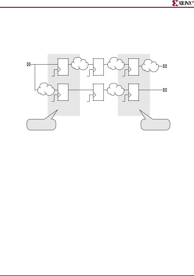
Move First Stage (MOVE_FIRST_STAGE)
Move First Stage (MOVE_FIRST_STAGE) controls the retiming of registers with paths coming from primary inputs. Both Move First Stage constraint and “Move Last Stage (MOVE_LAST_STAGE)” relate to Register Balancing.
XST User Guide |
www.xilinx.com |
389 |
10.1
Chapter 5: XST Design Constraints
Note:
R
•A flip-flop (FF in the diagram) belongs to the First Stage if it is on the paths coming from primary inputs.
•A flip-flop belongs to the Last Stage if it is on the paths going to primary outputs.
A |
LOGIC |
LOGIC |
|
|
Y1 |
|
FF |
LOGIC |
|||
|
FF |
FF |
|||
|
LOGIC |
LOGIC |
FF |
|
Y2 |
|
FF |
FF |
|
|
First FF |
Last FF |
Stage |
Stage |
X9564
Figure 5-2: Move First Stage
During register balancing:
•First Stage flip-flops are moved forward
•Last Stage flip-flops are moved backward.
This process can dramatically increase input-to-clock and clock-to-output timing, which is not desirable. To prevent this, you may use OFFSET_IN_BEFORE and OFFSET_IN_AFTER constraints.
In the case:
•The design does not have a strong requirements, or
•You want to see the first results without touching the first and last flip-flop stages.
Two additional constraints can be used: MOVE_FIRST_STAGE and MOVE_LAST_STAGE. Both constraints may have two values: yes and no.
•MOVE_FIRST_STAGE=no prevents the first flip-flop stage from moving
•MOVE_LAST_STAGE=no prevents the last flip-flop stage from moving
Several constraints influence register balancing. For more information, see “Register
Balancing (REGISTER_BALANCING).”
Move First Stage Architecture Support
Move First Stage applies to all FPGA devices. Move First Stage does not apply to CPLD devices.
390 |
www.xilinx.com |
XST User Guide |
10.1
R
XST FPGA Constraints (Non-Timing)
Move First Stage Applicable Elements
Move First Stage applies to the following only:
•Entire design
•Single modules or entities
•Primary clock signal
Move First Stage Propagation Rules
For Move First Stage propagation rules, see “Move First Stage (MOVE_FIRST_STAGE).”
Move First Stage Syntax Examples
Following are syntax examples using Move First Stage with particular tools or methods. If a tool or method is not listed, Move First Stage may not be used with it.
Move First Stage VHDL Syntax Example
Before using Move First Stage, declare it with the following syntax:
attribute move_first_stage : string;
After declaring Move First Stage, specify the VHDL constraint:
attribute move_first_stage of {entity_name|signal_name}: {signal|entity} is "{yes|no}";
Move First Stage Verilog Syntax Example
Place Move First Stage immediately before the module or signal declaration:
(* move_first_stage = "{yes|no}" *)
Move First Stage XCF Syntax Example One
MODEL "entity_name" move_first_stage={yes|no|true|false};
Move First Stage XCF Syntax Example Two
BEGIN MODEL "entity_name"
NET "primary_clock_signal" move_first_stage={yes|no|true|false};
END;
Move First Stage XST Command Line Syntax Example
Define Move First Stage globally with the –move_first_stage command line option of the run command:
-move_first_stage {yes|no}
The default is yes.
Move First Stage Project Navigator Syntax Example
Define Move First Stage globally in Project Navigator > Process Properties > Xilinx-Specific Options > Move First Flip-Flop Stage.
XST User Guide |
www.xilinx.com |
391 |
10.1