


R
Counters HDL Coding Techniques
input T, I; output O;
assign O = (~T) ? I: 1'bZ;
endmodule
Counters HDL Coding Techniques
This section discusses Counters HDL Coding Techniques, and includes:
•“About Counters”
•“Counters Log File”
•“Counters Related Constraints”
•“Counters Coding Examples”
About Counters
XST recognizes counters with the following control signals:
•Asynchronous Set/Reset
•Synchronous Set/Reset
•Asynchronous/Synchronous Load (signal or constant or both)
•Clock Enable
•Modes (Up, Down, Up/Down)
•Mixture of all of the above
HDL coding styles for the following control signals are equivalent to those described in “Registers HDL Coding Techniques.”
•Clock
•Asynchronous Set/Reset
•Synchronous Set/Reset
XST supports both unsigned and signed counters.
Counters Log File
The XST log file reports the type and size of recognized counters during the Macro
Recognition step.
...
Synthesizing Unit <counter>.
Related source file is counters_1.vhd. Found 4-bit up counter for signal <tmp>. Summary:
inferred 1 Counter(s). Unit <counter> synthesized.
==============================
HDL Synthesis Report |
|
Macro Statistics |
|
# Counters |
: 1 |
XST User Guide |
www.xilinx.com |
43 |
10.1

Chapter 2: XST HDL Coding Techniques
R
4-bit up counter |
: 1 |
==============================
...
During synthesis, XST decomposes Counters on Adders and Registers if they do not contain synchronous load signals. This is done to create additional opportunities for timing optimization. Because of this, counters reported during the Macro Recognition step and in the overall statistics of recognized macros may not appear in the final report. Adders and registers are reported instead.
Counters Related Constraints
•“Use DSP48 (USE_DSP48)”
•“DSP Utilization Ratio (DSP_UTILIZATION_RATIO)”
•“Keep (KEEP)”
Counters Coding Examples
This section gives the following Counters examples:
•“4-Bit Unsigned Up Counter With Asynchronous Reset”
•“4-Bit Unsigned Down Counter With Synchronous Set”
•“4-Bit Unsigned Up Counter With Asynchronous Load From Primary Input”
•“4-Bit Unsigned Up Counter With Synchronous Load With Constant”
•“4-Bit Unsigned Up Counter With Asynchronous Reset and Clock Enable”
•“4-Bit Unsigned Up/Down Counter With Asynchronous Reset”
•“4-Bit Signed Up Counter With Asynchronous Reset”
•“4-Bit Signed Up Counter With Asynchronous Reset and Modulo Maximum”
The coding examples in this section are accurate as of the date of publication. Download updates from ftp://ftp.xilinx.com/pub/documentation/misc/examples_v9.zip.
4-Bit Unsigned Up Counter With Asynchronous Reset
This section discusses 4-Bit Unsigned Up Counter With Asynchronous Reset, and includes:
•“4-Bit Unsigned Up Counter With Asynchronous Reset Diagram”
•“4-Bit Unsigned Up Counter With Asynchronous Reset Pin Descriptions”
•“4-Bit Unsigned Up Counter With Asynchronous Reset VHDL Coding Example”
•“4-Bit Unsigned Up Counter With Asynchronous Reset Verilog Coding Example”
44 |
www.xilinx.com |
XST User Guide |
|
|
10.1 |
R
Counters HDL Coding Techniques
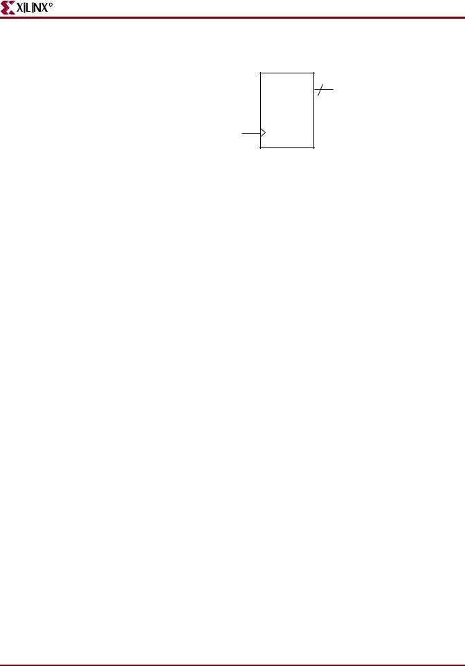
COUNT 4
Q
C
CLR |
|
X10526 |
|
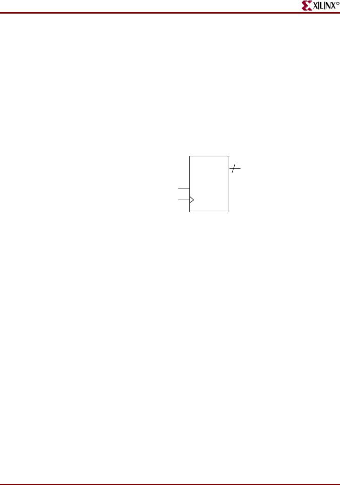
Figure 2-11: 4-Bit Unsigned Up Counter With Asynchronous Reset Diagram
Table 2-13: 4-Bit Unsigned Up Counter With Asynchronous Reset Pin Descriptions
IO Pins |
Description |
|
|
C |
Positive-Edge Clock |
|
|
CLR |
Asynchronous Reset (Active High) |
|
|
Q |
Data Output |
|
|
4-Bit Unsigned Up Counter With Asynchronous Reset VHDL Coding Example
--
-- 4-bit unsigned up counter with an asynchronous reset.
--
library ieee;
use ieee.std_logic_1164.all; use ieee.std_logic_unsigned.all;
entity counters_1 is
port(C, CLR : in std_logic;
Q : out std_logic_vector(3 downto 0)); end counters_1;
architecture archi of counters_1 is
signal tmp: std_logic_vector(3 downto 0); begin
process (C, CLR) begin
if (CLR='1') then tmp <= "0000";
elsif (C'event and C='1') then tmp <= tmp + 1;
end if; end process;
Q <= tmp;
end archi;
XST User Guide |
www.xilinx.com |
45 |
10.1
Chapter 2: XST HDL Coding Techniques
R
4-Bit Unsigned Up Counter With Asynchronous Reset Verilog Coding Example
//
// 4-bit unsigned up counter with an asynchronous reset.
//
module v_counters_1 (C, CLR, Q); input C, CLR;
output [3:0] Q; reg [3:0] tmp;
always @(posedge C or posedge CLR) begin
if (CLR)
tmp <= 4'b0000; else
tmp <= tmp + 1'b1;
end
assign Q = tmp; endmodule
4-Bit Unsigned Down Counter With Synchronous Set
This section discusses 4-Bit Unsigned Down Counter With Synchronous Set, and includes:
•“4-Bit Unsigned Down Counter With Synchronous Set VHDL Coding Example”
•“4-Bit Unsigned Down Counter With Synchronous Set Verilog Coding Example”
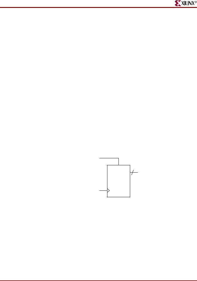
S
COUNT 4
Q
C
X10527
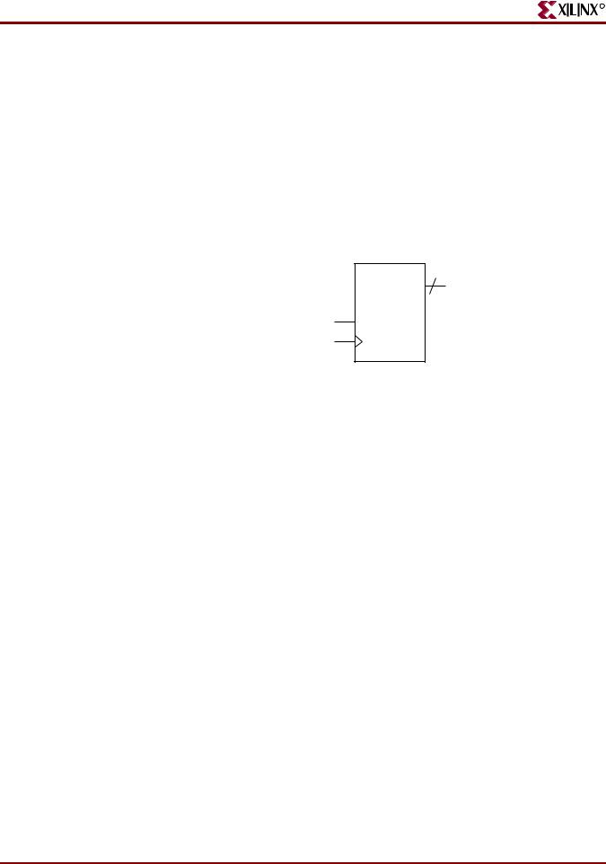
Figure 2-12: 4-Bit Unsigned Down Counter With Synchronous Set Diagram
Table 2-14: 4-Bit Unsigned Down Counter With Synchronous Set Pin Descriptions
IO Pins |
Description |
|
|
C |
Positive-Edge Clock |
|
|
S |
Synchronous Set (Active High) |
|
|
Q |
Data Output |
|
|
46 |
www.xilinx.com |
XST User Guide |
|
|
10.1 |

R
Counters HDL Coding Techniques
4-Bit Unsigned Down Counter With Synchronous Set VHDL Coding Example
--
-- 4-bit unsigned down counter with a synchronous set.
--
library ieee;
use ieee.std_logic_1164.all; use ieee.std_logic_unsigned.all;
entity counters_2 is
port(C, S : in std_logic;
Q : out std_logic_vector(3 downto 0)); end counters_2;
architecture archi of counters_2 is
signal tmp: std_logic_vector(3 downto 0); begin
process (C) begin
if (C'event and C='1') then if (S='1') then
tmp <= "1111";
else
tmp <= tmp - 1; end if;
end if; end process;
Q <= tmp;
end archi;
4-Bit Unsigned Down Counter With Synchronous Set Verilog Coding Example
//
// 4-bit unsigned down counter with a synchronous set.
//
module v_counters_2 (C, S, Q); input C, S;
output [3:0] Q; reg [3:0] tmp;
always @(posedge C) begin
if (S)
tmp <= 4'b1111; else
tmp <= tmp - 1'b1;
end
assign Q = tmp;
endmodule
XST User Guide |
www.xilinx.com |
47 |
10.1
Chapter 2: XST HDL Coding Techniques
4-Bit Unsigned Up Counter With Asynchronous Load From Primary Input
R
This section discusses 4-Bit Unsigned Up Counter With Asynchronous Load From Primary Input, and includes:
•“4-Bit Unsigned Up Counter With Asynchronous Load From Primary Input Diagram”
•“4-Bit Unsigned Up Counter With Asynchronous Load From Primary Input Pin Descriptions”
•“4-Bit Unsigned Up Counter With Asynchronous Load From Primary Input VHDL Coding Example”
•“4-Bit Unsigned Up Counter With Asynchronous Load From Primary Input Verilog Coding Example”
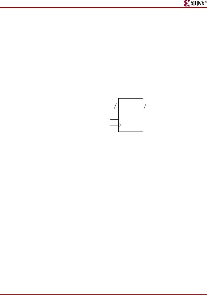
4 |
COUNT |
4 |
|
|
D |
|
|
Q |
|
|
|
|
||
|
|
|
||
ALOAD
C
X10528
Figure 2-13: 4-Bit Unsigned Up Counter With Asynchronous Load From Primary Input
Diagram
Table 2-15: 4-Bit Unsigned Up Counter With Asynchronous Load From Primary Input Pin Descriptions
IO Pins |
Description |
|
|
C |
Positive-Edge Clock |
|
|
ALOAD |
Asynchronous Load (Active High) |
|
|
D |
Data Input |
|
|
Q |
Data Output |
|
|
4-Bit Unsigned Up Counter With Asynchronous Load From Primary Input VHDL Coding Example
--
-- 4-bit Unsigned Up Counter with Asynchronous Load from Primary Input
--
library ieee;
use ieee.std_logic_1164.all; use ieee.std_logic_unsigned.all;
entity counters_3 is
port(C, ALOAD : in std_logic;
D : in std_logic_vector(3 downto 0);
48 |
www.xilinx.com |
XST User Guide |
|
|
10.1 |

R
Counters HDL Coding Techniques
Q : out std_logic_vector(3 downto 0)); end counters_3;
architecture archi of counters_3 is
signal tmp: std_logic_vector(3 downto 0); begin
process (C, ALOAD, D) begin
if (ALOAD='1') then tmp <= D;
elsif (C'event and C='1') then tmp <= tmp + 1;
end if; end process;
Q <= tmp;
end archi;
4-Bit Unsigned Up Counter With Asynchronous Load From Primary Input Verilog Coding Example
//
// 4-bit Unsigned Up Counter with Asynchronous Load from Primary Input
//
module v_counters_3 (C, ALOAD, D, Q); input C, ALOAD;
input [3:0] D; output [3:0] Q; reg [3:0] tmp;
always @(posedge C or posedge ALOAD) begin
if (ALOAD) tmp <= D;
else
tmp <= tmp + 1'b1;
end
assign Q = tmp;
endmodule
4-Bit Unsigned Up Counter With Synchronous Load With Constant
This section discusses 4-Bit Unsigned Up Counter With Synchronous Load With Constant, and includes:
•“4-Bit Unsigned Up Counter With Synchronous Load With Constant Diagram”
•“4-Bit Unsigned Up Counter With Synchronous Load With Constant Pin Descriptions”
•“4-Bit Unsigned Up Counter With Synchronous Load With Constant VHDL Coding Example”
•“4-Bit Unsigned Up Counter With Synchronous Load With Constant Verilog Coding Example”
XST User Guide |
www.xilinx.com |
49 |
10.1
Chapter 2: XST HDL Coding Techniques
R
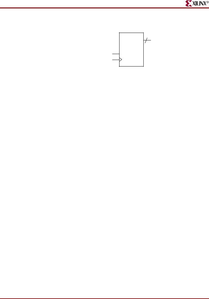
COUNT 4
Q
SLOAD
C
X10529
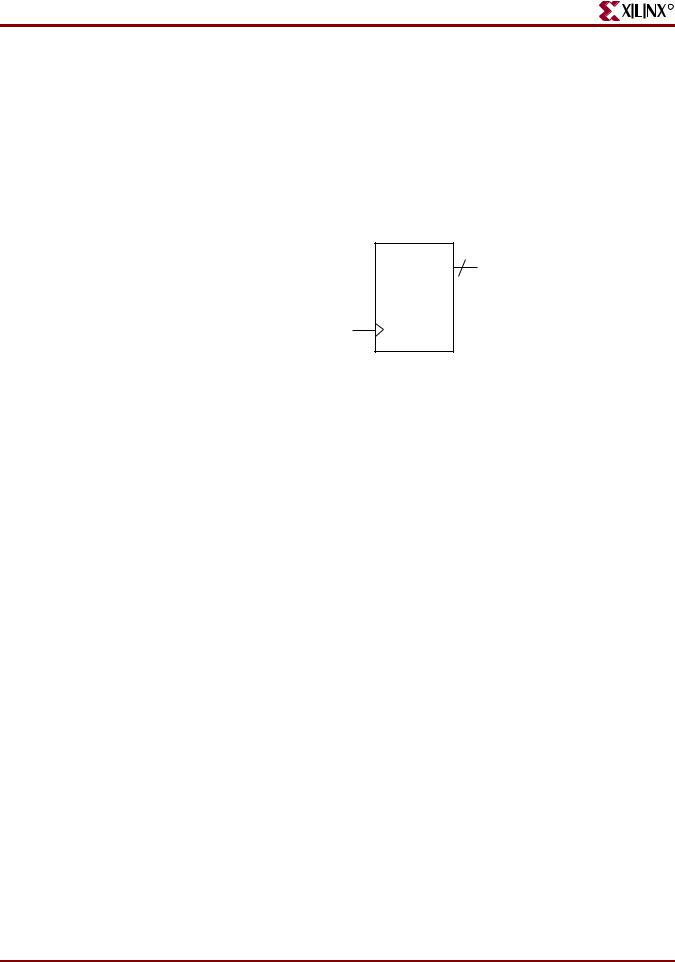
Figure 2-14: 4-Bit Unsigned Up Counter With Synchronous Load With Constant Diagram
Table 2-16: 4-Bit Unsigned Up Counter With Synchronous Load With Constant Pin
Descriptions
IO Pins |
Description |
|
|
C |
Positive-Edge Clock |
|
|
SLOAD |
Synchronous Load (Active High) |
|
|
Q |
Data Output |
|
|
4-Bit Unsigned Up Counter With Synchronous Load With Constant VHDL Coding Example
--
-- 4-bit Unsigned Up Counter with Synchronous Load with a Constant
--
library ieee;
use ieee.std_logic_1164.all; use ieee.std_logic_unsigned.all;
entity counters_4 is
port(C, SLOAD : in std_logic;
Q : out std_logic_vector(3 downto 0)); end counters_4;
architecture archi of counters_4 is
signal tmp: std_logic_vector(3 downto 0); begin
process (C) begin
if (C'event and C='1') then if (SLOAD='1') then
tmp <= "1010";
else
tmp <= tmp + 1; end if;
end if; end process;
Q <= tmp;
end archi;
50 |
www.xilinx.com |
XST User Guide |
|
|
10.1 |
R
Counters HDL Coding Techniques
4-Bit Unsigned Up Counter With Synchronous Load With Constant Verilog Coding Example
//
// 4-bit Unsigned Up Counter with Synchronous Load with a Constant
//
module v_counters_4 (C, SLOAD, Q); input C, SLOAD;
output [3:0] Q; reg [3:0] tmp;
always @(posedge C) begin
if (SLOAD)
tmp <= 4'b1010; else
tmp <= tmp + 1'b1;
end
assign Q = tmp;
endmodule
XST User Guide |
www.xilinx.com |
51 |
10.1
Chapter 2: XST HDL Coding Techniques
R
4-Bit Unsigned Up Counter With Asynchronous Reset and Clock Enable
This section discusses 4-Bit Unsigned Up Counter With Asynchronous Reset and Clock Enable, and includes:
•“4-Bit Unsigned Up Counter With Asynchronous Reset and Clock Enable Diagram”
•“4-Bit Unsigned Up Counter With Asynchronous Reset and Clock Enable Pin Descriptions”
•“4-Bit Unsigned Up Counter With Asynchronous Reset and Clock Enable VHDL Coding Example”
•“4-Bit Unsigned Up Counter With Asynchronous Reset and Clock Enable Verilog Coding Example”
COUNT 4
Q
CE
C
CLR |
|
X10530 |
|
Figure 2-15: 4-Bit Unsigned Up Counter With Asynchronous Reset and Clock Enable
Diagram
Table 2-17: 4-Bit Unsigned Up Counter With Asynchronous Reset and Clock Enable Pin Descriptions
IO Pins |
Description |
|
|
C |
Positive-Edge Clock |
|
|
CLR |
Asynchronous Reset (Active High) |
|
|
CE |
Clock Enable |
|
|
Q |
Data Output |
|
|
4-Bit Unsigned Up Counter With Asynchronous Reset and Clock Enable VHDL Coding Example
--
-- 4-bit Unsigned Up Counter with Asynchronous Reset and Clock Enable
--
library ieee;
use ieee.std_logic_1164.all; use ieee.std_logic_unsigned.all;
entity counters_5 is
port(C, CLR, CE : in std_logic;
Q : out std_logic_vector(3 downto 0));
52 |
www.xilinx.com |
XST User Guide |
|
|
10.1 |

R
Counters HDL Coding Techniques
end counters_5;
architecture archi of counters_5 is
signal tmp: std_logic_vector(3 downto 0); begin
process (C, CLR) begin
if (CLR='1') then tmp <= "0000";
elsif (C'event and C='1') then if (CE='1') then
tmp <= tmp + 1; end if;
end if; end process;
Q <= tmp;
end archi;
4-Bit Unsigned Up Counter With Asynchronous Reset and Clock Enable Verilog Coding Example
//
// 4-bit Unsigned Up Counter with Asynchronous Reset and Clock Enable
//
module v_counters_5 (C, CLR, CE, Q); input C, CLR, CE;
output [3:0] Q; reg [3:0] tmp;
always @(posedge C or posedge CLR) begin
if (CLR)
tmp <= 4'b0000; else if (CE)
tmp <= tmp + 1'b1;
end
assign Q = tmp;
endmodule
XST User Guide |
www.xilinx.com |
53 |
10.1
Chapter 2: XST HDL Coding Techniques
R
4-Bit Unsigned Up/Down Counter With Asynchronous Reset
This section discusses 4-Bit Unsigned Up/Down Counter With Asynchronous Reset, and includes:
•“4-Bit Unsigned Up/Down Counter With Asynchronous Reset Diagram”
•“4-Bit Unsigned Up/Down Counter With Asynchronous Reset Pin Descriptions”
•“4-Bit Unsigned Up/Down Counter With Asynchronous Reset VHDL Coding Example”
•“4-Bit Unsigned Up/Down Counter With Asynchronous Reset Verilog Coding Example”
COUNT 4
Q
UP_Down
C
CLR |
|
X10531 |
|
Figure 2-16: 4-Bit Unsigned Up/Down Counter With Asynchronous Reset Diagram
Table 2-18: 4-Bit Unsigned Up/Down Counter With Asynchronous Reset Pin
Descriptions
IO Pins |
Description |
|
|
C |
Positive-Edge Clock |
|
|
CLR |
Asynchronous Reset (Active High) |
|
|
UP_DOWN |
Up/Down Count Mode Selector |
|
|
Q |
Data Output |
|
|
4-Bit Unsigned Up/Down Counter With Asynchronous Reset VHDL Coding Example
--
-- 4-bit Unsigned Up/Down counter with Asynchronous Reset
--
library ieee;
use ieee.std_logic_1164.all; use ieee.std_logic_unsigned.all;
entity counters_6 is
port(C, CLR, UP_DOWN : in std_logic;
Q : out std_logic_vector(3 downto 0)); end counters_6;
architecture archi of counters_6 is
signal tmp: std_logic_vector(3 downto 0);
54 |
www.xilinx.com |
XST User Guide |
|
|
10.1 |

R
Counters HDL Coding Techniques
begin
process (C, CLR) begin
if (CLR='1') then tmp <= "0000";
elsif (C'event and C='1') then if (UP_DOWN='1') then
tmp <= tmp + 1;
else
tmp <= tmp - 1; end if;
end if; end process;
Q <= tmp;
end archi;
4-Bit Unsigned Up/Down Counter With Asynchronous Reset Verilog Coding Example
//
// 4-bit Unsigned Up/Down counter with Asynchronous Reset
//
module v_counters_6 (C, CLR, UP_DOWN, Q); input C, CLR, UP_DOWN;
output [3:0] Q; reg [3:0] tmp;
always @(posedge C or posedge CLR) begin
if (CLR)
tmp <= 4'b0000; else if (UP_DOWN)
tmp <= tmp + 1'b1;
else
tmp <= tmp - 1'b1;
end
assign Q = tmp;
endmodule
XST User Guide |
www.xilinx.com |
55 |
10.1
Chapter 2: XST HDL Coding Techniques
R
4-Bit Signed Up Counter With Asynchronous Reset
This section discusses 4-Bit Signed Up Counter With Asynchronous Reset, and includes:
•“4-Bit Signed Up Counter With Asynchronous Reset Diagram”
•“4-Bit Signed Up Counter With Asynchronous Reset Pin Descriptions”
•“4-Bit Signed Up Counter With Asynchronous Reset VHDL Coding Example”
•“4-Bit Signed Up Counter With Asynchronous Reset Verilog Coding Example”
COUNT 4
Q
C
CLR |
|
X10532 |
|
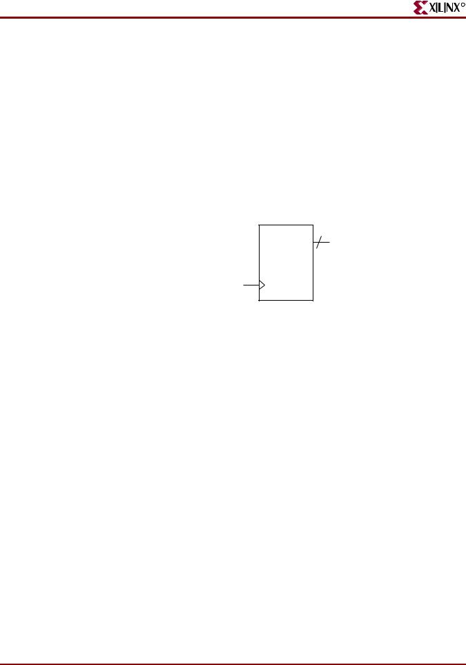
Figure 2-17: 4-Bit Signed Up Counter With Asynchronous Reset Diagram
Table 2-19: 4-Bit Signed Up Counter With Asynchronous Reset Pin Descriptions
IO Pins |
Description |
|
|
C |
Positive-Edge Clock |
|
|
CLR |
Asynchronous Reset (Active High) |
|
|
Q |
Data Output |
|
|
4-Bit Signed Up Counter With Asynchronous Reset VHDL Coding Example
--
-- 4-bit Signed Up Counter with Asynchronous Reset
--
library ieee;
use ieee.std_logic_1164.all; use ieee.std_logic_signed.all;
entity counters_7 is
port(C, CLR : in std_logic;
Q : out std_logic_vector(3 downto 0)); end counters_7;
architecture archi of counters_7 is
signal tmp: std_logic_vector(3 downto 0); begin
process (C, CLR) begin
if (CLR='1') then tmp <= "0000";
56 |
www.xilinx.com |
XST User Guide |
|
|
10.1 |

R
Counters HDL Coding Techniques
elsif (C'event and C='1') then tmp <= tmp + 1;
end if; end process;
Q <= tmp;
end archi;
4-Bit Signed Up Counter With Asynchronous Reset Verilog Coding Example
//
// 4-bit Signed Up Counter with Asynchronous Reset
//
module v_counters_7 (C, CLR, Q); input C, CLR;
output signed [3:0] Q; reg signed [3:0] tmp;
always @ (posedge C or posedge CLR) begin
if (CLR)
tmp <= 4'b0000; else
tmp <= tmp + 1'b1;
end
assign Q = tmp;
endmodule
XST User Guide |
www.xilinx.com |
57 |
10.1
Chapter 2: XST HDL Coding Techniques
R
4-Bit Signed Up Counter With Asynchronous Reset and Modulo Maximum
This section discusses 4-Bit Signed Up Counter With Asynchronous Reset and Modulo Maximum, and includes:
•“4-Bit Signed Up Counter With Asynchronous Reset and Modulo Maximum Diagram”
•“4-Bit Signed Up Counter With Asynchronous Reset and Modulo Maximum Pin Descriptions”
•“4-Bit Signed Up Counter With Asynchronous Reset and Modulo Maximum VHDL Coding Example”
•“4-Bit Signed Up Counter With Asynchronous Reset and Modulo Maximum Verilog Coding Example”
COUNT 4
Q
C
CLR |
|
X10532 |
|
Figure 2-18: 4-Bit Signed Up Counter With Asynchronous Reset and Modulo Maximum
Diagram
Table 2-20: 4-Bit Signed Up Counter With Asynchronous Reset and Modulo Maximum Pin Descriptions
IO Pins |
Description |
|
|
C |
Positive-Edge Clock |
|
|
CLR |
Asynchronous Reset (Active High) |
|
|
Q |
Data Output |
|
|
4-Bit Signed Up Counter With Asynchronous Reset and Modulo Maximum VHDL Coding Example
--
-- 4-bit Signed Up Counter with Asynchronous Reset and Modulo Maximum
--
library ieee;
use ieee.std_logic_1164.all; use ieee.std_logic_arith.all;
entity counters_8 is
generic (MAX : integer := 16); port(C, CLR : in std_logic;
Q : out integer range 0 to MAX-1);
58 |
www.xilinx.com |
XST User Guide |
|
|
10.1 |

R
Counters HDL Coding Techniques
end counters_8;
architecture archi of counters_8 is signal cnt : integer range 0 to MAX-1;
begin
process (C, CLR) begin
if (CLR='1') then cnt <= 0;
elsif (rising_edge(C)) then cnt <= (cnt + 1) mod MAX ;
end if; end process;
Q <= cnt;
end archi;
4-Bit Signed Up Counter With Asynchronous Reset and Modulo Maximum Verilog Coding Example
//
// 4-bit Signed Up Counter with Asynchronous Reset and Modulo Maximum
//
module v_counters_8 (C, CLR, Q); parameter
MAX_SQRT = 4,
MAX = (MAX_SQRT*MAX_SQRT);
input |
C, CLR; |
output |
[MAX_SQRT-1:0] Q; |
reg |
[MAX_SQRT-1:0] cnt; |
always @ (posedge C or posedge CLR) begin
if (CLR)
cnt <= 0; else
cnt <= (cnt + 1) %MAX;
end
assign Q = cnt;
endmodule
XST User Guide |
www.xilinx.com |
59 |
10.1