

- •XST User Guide
- •Table of Contents
- •About the XST User Guide
- •XST User Guide Contents
- •Additional Resources
- •Conventions
- •Typographical
- •Online Document
- •1 Introduction to the XST User Guide
- •About XST
- •What’s New in Release 10.1
- •Macro Inference
- •Constraints
- •Libraries Support
- •Setting XST Options
- •2 XST HDL Coding Techniques
- •Signed and Unsigned Support in XST
- •Registers HDL Coding Techniques
- •About Registers
- •Registers Log File
- •Registers Related Constraints
- •Registers Coding Examples
- •Latches HDL Coding Techniques
- •About Latches
- •Latches Log File
- •Latches Related Constraints
- •Latches Coding Examples
- •Tristates HDL Coding Techniques
- •About Tristates
- •Tristates Log File
- •Tristates Related Constraints
- •Tristates Coding Examples
- •Counters HDL Coding Techniques
- •About Counters
- •Counters Log File
- •Counters Related Constraints
- •Counters Coding Examples
- •Accumulators HDL Coding Techniques
- •About Accumulators
- •Accumulators in Virtex-4 and Virtex-5 Devices
- •Accumulators Log File
- •Accumulators Related Constraints
- •Accumulators Coding Examples
- •Shift Registers HDL Coding Techniques
- •About Shift Registers
- •Describing Shift Registers
- •Implementing Shift Registers
- •Shift Registers Log File
- •Shift Registers Related Constraints
- •Shift Registers Coding Examples
- •Dynamic Shift Registers HDL Coding Techniques
- •About Dynamic Shift Registers
- •Dynamic Shift Registers Log File
- •Dynamic Shift Registers Related Constraints
- •Dynamic Shift Registers Coding Examples
- •Multiplexers HDL Coding Techniques
- •About Multiplexers
- •Multiplexers Case Statements
- •Multiplexers Log File
- •Multiplexers Related Constraints
- •Multiplexers Coding Examples
- •Decoders HDL Coding Techniques
- •About Decoders
- •Decoders Log File
- •Decoders Related Constraints
- •Decoders Coding Examples
- •Priority Encoders HDL Coding Techniques
- •About Priority Encoders
- •Priority Encoders Log File
- •Priority Encoders Related Constraints
- •Priority Encoders Coding Examples
- •Logical Shifters HDL Coding Techniques
- •About Logical Shifters
- •Logical Shifters Log File
- •Logical Shifters Related Constraints
- •Logical Shifters Coding Examples
- •Arithmetic Operators HDL Coding Techniques
- •About Arithmetic Operators
- •Arithmetic Operators Log File
- •Arithmetic Operators Related Constraints
- •Arithmetic Operators Coding Examples
- •About Adders, Subtractors, and Adders/Subtractors
- •Adders, Subtractors, and Adders/Subtractors Log File
- •Adders, Subtractors, and Adders/Subtractors Related Constraints
- •Adders, Subtractors, and Adders/Subtractors Coding Examples
- •Comparators HDL Coding Techniques
- •About Comparators
- •Comparators Log File
- •Comparators Related Constraints
- •Comparators Coding Examples
- •Multipliers HDL Coding Techniques
- •About Multipliers
- •Large Multipliers Using Block Multipliers
- •Registered Multipliers
- •Multipliers (Virtex-4, Virtex-5, and Spartan-3A D Devices)
- •Multiplication with Constant
- •Multipliers Log File
- •Multipliers Related Constraints
- •Multipliers Coding Examples
- •Sequential Complex Multipliers HDL Coding Techniques
- •About Sequential Complex Multipliers
- •Sequential Complex Multipliers Log File
- •Sequential Complex Multipliers Related Constraints
- •Sequential Complex Multipliers Coding Examples
- •Pipelined Multipliers HDL Coding Techniques
- •About Pipelined Multipliers
- •Pipelined Multipliers Log File
- •Pipelined Multipliers Related Constraints
- •Pipelined Multipliers Coding Examples
- •Multiply Adder/Subtractors HDL Coding Techniques
- •About Multiply Adder/Subtractors
- •Multiply Adder/Subtractors in Virtex-4 and Virtex- 5 Devices
- •Multiply Adder/Subtractors Log File
- •Multiply Adder/Subtractors Related Constraints
- •Multiply Adder/Subtractors Coding Examples
- •Multiply Accumulate HDL Coding Techniques
- •About Multiply Accumulate
- •Multiply Accumulate in Virtex-4 and Virtex-5 Devices
- •Multiply Accumulate Log File
- •Multiply Accumulate Related Constraints
- •Multiply Accumulate Coding Examples
- •Dividers HDL Coding Techniques
- •About Dividers
- •Dividers Log File
- •Dividers Related Constraints
- •Dividers Coding Examples
- •Resource Sharing HDL Coding Techniques
- •About Resource Sharing
- •Resource Sharing Log File
- •Resource Sharing Related Constraints
- •Resource Sharing Coding Examples
- •RAMs and ROMs HDL Coding Techniques
- •About RAMs and ROMs
- •RAMs and ROMs Log File
- •RAMs and ROMs Related Constraints
- •RAMs and ROMs Coding Examples
- •Initializing RAM Coding Examples
- •ROMs Using Block RAM Resources HDL Coding Techniques
- •About ROMs Using Block RAM Resources
- •ROMs Using Block RAM Resources Log File
- •ROMs Using Block RAM Resources Related Constraints
- •ROMs Using Block RAM Resources Coding Examples
- •Pipelined Distributed RAM HDL Coding Techniques
- •About Pipelined Distributed RAM
- •Pipelined Distributed RAM Log File
- •Pipelined Distributed RAM Related Constraints
- •Pipelined Distributed RAM Coding Examples
- •Finite State Machines (FSMs) HDL Coding Techniques
- •About Finite State Machines (FSMs)
- •Describing Finite State Machines (FSMs)
- •State Encoding Techniques
- •RAM-Based FSM Synthesis
- •Safe FSM Implementation
- •Finite State Machines Log File
- •Finite State Machines Related Constraints
- •Finite State Machines Coding Examples
- •Black Boxes HDL Coding Techniques
- •About Black Boxes
- •Black Box Log File
- •Black Box Related Constraints
- •Black Box Coding Examples
- •3 XST FPGA Optimization
- •About XST FPGA Optimization
- •Virtex-Specific Synthesis Options
- •Macro Generation
- •Virtex Macro Generator
- •Arithmetic Functions in Macro Generation
- •Loadable Functions in Macro Generation
- •Multiplexers in Macro Generation
- •Priority Encoders in Macro Generation
- •Decoders in Macro Generation
- •Shift Registers in Macro Generation
- •RAMs in Macro Generation
- •ROMs in Macro Generation
- •DSP48 Block Resources
- •Mapping Logic Onto Block RAM
- •About Mapping Logic Onto Block RAM
- •Mapping Logic Onto Block RAM Log Files
- •Mapping Logic Onto Block RAM Coding Examples
- •Flip-Flop Retiming
- •About Flip-Flop Retiming
- •Limitations of Flip-Flop Retiming
- •Controlling Flip-Flop Retiming
- •Partitions
- •Incremental Synthesis
- •About Incremental Synthesis
- •Incremental Synthesis (INCREMENTAL_SYNTHESIS)
- •Grouping Through Incremental Synthesis Diagram
- •Resynthesize (RESYNTHESIZE)
- •Speed Optimization Under Area Constraint
- •About Speed Optimization Under Area Constraint
- •Speed Optimization Under Area Constraint Examples
- •FPGA Optimization Log File
- •Design Optimization Report
- •Cell Usage Report
- •Timing Report
- •Implementation Constraints
- •Virtex Primitive Support
- •Instantiating Virtex Primitives
- •Generating Primitives Through Attributes
- •Primitives and Black Boxes
- •VHDL and Verilog Virtex Libraries
- •Virtex Primitives Log File
- •Virtex Primitives Related Constraints
- •Virtex Primitives Coding Examples
- •Using the UNIMACRO Library
- •Cores Processing
- •Specifying INIT and RLOC
- •About Specifying INIT and RLOC
- •Passing an INIT Value Via the LUT_MAP Constraint Coding Examples
- •Specifying INIT Value for a Flip-Flop Coding Examples
- •Specifying INIT and RLOC Values for a Flip-Flop Coding Examples
- •Using PCI Flow With XST
- •Satisfying Placement Constraints and Meeting Timing Requirements
- •Preventing Logic and Flip-Flop Replication
- •Disabling Read Cores
- •4 XST CPLD Optimization
- •CPLD Synthesis Options
- •About CPLD Synthesis Options
- •CPLD Synthesis Supported Devices
- •Setting CPLD Synthesis Options
- •Implementation Details for Macro Generation
- •CPLD Synthesis Log File Analysis
- •CPLD Synthesis Constraints
- •Improving Results in CPLD Synthesis
- •About Improving Results in CPLD Synthesis
- •Obtaining Better Frequency
- •Fitting a Large Design
- •5 XST Design Constraints
- •About Constraints
- •List of XST Design Constraints
- •XST General Constraints
- •XST HDL Constraints
- •XST FPGA Constraints (Non-Timing)
- •XST CPLD Constraints (Non-Timing)
- •XST Timing Constraints
- •XST Implementation Constraints
- •Third Party Constraints
- •Setting Global Constraints and Options
- •Setting Synthesis Options
- •Setting HDL Options
- •Setting Xilinx-Specific Options
- •Setting Other XST Command Line Options
- •Custom Compile File List
- •VHDL Attribute Syntax
- •Verilog-2001 Attributes
- •About Verilog-2001 Attributes
- •Verilog-2001 Attributes Syntax
- •Verilog-2001 Limitations
- •Verilog-2001 Meta Comments
- •XST Constraint File (XCF)
- •Specifying the XST Constraint File (XCF)
- •XCF Syntax and Utilization
- •Native and Non-Native User Constraint File (UCF) Constraints Syntax
- •XCF Syntax Limitations
- •Constraints Priority
- •XST-Specific Non-Timing Options
- •XST Command Line Only Options
- •XST Timing Options
- •XST Timing Options: Project Navigator > Process Properties or Command Line
- •XST Timing Options: Xilinx Constraint File (XCF)
- •XST General Constraints
- •Add I/O Buffers (–iobuf)
- •BoxType (BOX_TYPE)
- •Bus Delimiter (–bus_delimiter)
- •Case (–case)
- •Case Implementation Style (–vlgcase)
- •Verilog Macros (-define)
- •Duplication Suffix (–duplication_suffix)
- •Full Case (FULL_CASE)
- •Generate RTL Schematic (–rtlview)
- •Generics (-generics)
- •Hierarchy Separator (–hierarchy_separator)
- •I/O Standard (IOSTANDARD)
- •Keep (KEEP)
- •Keep Hierarchy (KEEP_HIERARCHY)
- •Library Search Order (–lso)
- •Netlist Hierarchy (-netlist_hierarchy)
- •Optimization Effort (OPT_LEVEL)
- •Optimization Goal (OPT_MODE)
- •Parallel Case (PARALLEL_CASE)
- •RLOC
- •Save (S / SAVE)
- •Synthesis Constraint File (–uc)
- •Use Synthesis Constraints File (–iuc)
- •Verilog Include Directories (–vlgincdir)
- •Verilog 2001 (–verilog2001)
- •HDL Library Mapping File (–xsthdpini)
- •Work Directory (–xsthdpdir)
- •XST HDL Constraints
- •About XST HDL Constraints
- •Automatic FSM Extraction (FSM_EXTRACT)
- •Enumerated Encoding (ENUM_ENCODING)
- •Equivalent Register Removal (EQUIVALENT_REGISTER_REMOVAL)
- •FSM Encoding Algorithm (FSM_ENCODING)
- •Mux Extraction (MUX_EXTRACT)
- •Register Power Up (REGISTER_POWERUP)
- •Resource Sharing (RESOURCE_SHARING)
- •Safe Recovery State (SAFE_RECOVERY_STATE)
- •Safe Implementation (SAFE_IMPLEMENTATION)
- •Signal Encoding (SIGNAL_ENCODING)
- •XST FPGA Constraints (Non-Timing)
- •Asynchronous to Synchronous (ASYNC_TO_SYNC)
- •Automatic BRAM Packing (AUTO_BRAM_PACKING)
- •BRAM Utilization Ratio (BRAM_UTILIZATION_RATIO)
- •Buffer Type (BUFFER_TYPE)
- •Extract BUFGCE (BUFGCE)
- •Cores Search Directories (–sd)
- •Decoder Extraction (DECODER_EXTRACT)
- •DSP Utilization Ratio (DSP_UTILIZATION_RATIO)
- •FSM Style (FSM_STYLE)
- •Power Reduction (POWER)
- •Read Cores (READ_CORES)
- •Resynthesize (RESYNTHESIZE)
- •Incremental Synthesis (INCREMENTAL_SYNTHESIS)
- •Logical Shifter Extraction (SHIFT_EXTRACT)
- •LUT Combining (LC)
- •Map Logic on BRAM (BRAM_MAP)
- •Max Fanout (MAX_FANOUT)
- •Move First Stage (MOVE_FIRST_STAGE)
- •Move Last Stage (MOVE_LAST_STAGE)
- •Multiplier Style (MULT_STYLE)
- •Mux Style (MUX_STYLE)
- •Number of Global Clock Buffers (–bufg)
- •Number of Regional Clock Buffers (–bufr)
- •Optimize Instantiated Primitives (OPTIMIZE_PRIMITIVES)
- •Pack I/O Registers Into IOBs (IOB)
- •Priority Encoder Extraction (PRIORITY_EXTRACT)
- •RAM Extraction (RAM_EXTRACT)
- •RAM Style (RAM_STYLE)
- •Reduce Control Sets (REDUCE_CONTROL_SETS)
- •Register Balancing (REGISTER_BALANCING)
- •Register Duplication (REGISTER_DUPLICATION)
- •ROM Extraction (ROM_EXTRACT)
- •ROM Style (ROM_STYLE)
- •Shift Register Extraction (SHREG_EXTRACT)
- •Slice Packing (–slice_packing)
- •Use Low Skew Lines (USELOWSKEWLINES)
- •XOR Collapsing (XOR_COLLAPSE)
- •Slice (LUT-FF Pairs) Utilization Ratio (SLICE_UTILIZATION_RATIO)
- •Map Entity on a Single LUT (LUT_MAP)
- •Use Carry Chain (USE_CARRY_CHAIN)
- •Convert Tristates to Logic (TRISTATE2LOGIC)
- •Use Clock Enable (USE_CLOCK_ENABLE)
- •Use Synchronous Set (USE_SYNC_SET)
- •Use Synchronous Reset (USE_SYNC_RESET)
- •XST CPLD Constraints (Non-Timing)
- •Clock Enable (–pld_ce)
- •Data Gate (DATA_GATE)
- •Macro Preserve (–pld_mp)
- •No Reduce (NOREDUCE)
- •WYSIWYG (–wysiwyg)
- •XOR Preserve (–pld_xp)
- •XST Timing Constraints
- •Applying Timing Constraints
- •Cross Clock Analysis (–cross_clock_analysis)
- •Write Timing Constraints (–write_timing_constraints)
- •Clock Signal (CLOCK_SIGNAL)
- •Global Optimization Goal (–glob_opt)
- •XCF Timing Constraint Support
- •Period (PERIOD)
- •Offset (OFFSET)
- •From-To (FROM-TO)
- •Timing Name (TNM)
- •Timing Name on a Net (TNM_NET)
- •Timegroup (TIMEGRP)
- •Timing Ignore (TIG)
- •XST Implementation Constraints
- •About Implementation Constraints
- •Implementation Constraints Syntax Examples
- •RLOC
- •NOREDUCE
- •PWR_MODE
- •XST-Supported Third Party Constraints
- •XST Equivalents to Third Party Constraints
- •Third Party Constraints Syntax Examples
- •6 XST VHDL Language Support
- •About XST VHDL Language Support
- •VHDL IEEE Support
- •About VHDL IEEE Support
- •VHDL IEEE Conflicts
- •Non-LRM Compliant Constructs in VHDL
- •XST VHDL File Type Support
- •About XST VHDL File Type Support
- •XST VHDL File Type Support Table
- •Debugging Using Write Operation in VHDL
- •Rules for Debugging Using Write Operation in VHDL
- •VHDL Data Types
- •Accepted VHDL Data Types
- •VHDL Overloaded Data Types
- •VHDL Multi-Dimensional Array Types
- •VHDL Record Types
- •VHDL Initial Values
- •About VHDL Initial Values
- •VHDL Local Reset/Global Reset
- •Default Initial Values on Memory Elements in VHDL
- •VHDL Objects
- •Signals in VHDL
- •Variables in VHDL
- •Constants in VHDL
- •VHDL Operators
- •Entity and Architecture Descriptions in VHDL
- •VHDL Circuit Descriptions
- •VHDL Entity Declarations
- •VHDL Architecture Declarations
- •VHDL Component Instantiation
- •VHDL Recursive Component Instantiation
- •VHDL Component Configuration
- •VHDL Generic Parameter Declarations
- •VHDL Generic and Attribute Conflicts
- •VHDL Combinatorial Circuits
- •VHDL Concurrent Signal Assignments
- •VHDL Generate Statements
- •VHDL Combinatorial Processes
- •VHDL If...Else Statements
- •VHDL Case Statements
- •VHDL For...Loop Statements
- •VHDL Sequential Circuits
- •About VHDL Sequential Circuits
- •VHDL Sequential Process With a Sensitivity List
- •VHDL Sequential Process Without a Sensitivity List
- •Register and Counter Descriptions VHDL Coding Examples
- •VHDL Multiple Wait Statements Descriptions
- •VHDL Functions and Procedures
- •About VHDL Functions and Procedures
- •VHDL Functions and Procedures Examples
- •VHDL Assert Statements
- •About VHDL Assert Statements
- •SINGLE_SRL Describing a Shift Register
- •Using Packages to Define VHDL Models
- •About Using Packages to Define VHDL Models
- •Using Standard Packages to Define VHDL Models
- •Using IEEE Packages to Define VHDL Models
- •Using Synopsys Packages to Define VHDL Models
- •VHDL Constructs Supported in XST
- •VHDL Design Entities and Configurations
- •VHDL Expressions
- •VHDL Statements
- •VHDL Reserved Words
- •7 XST Verilog Language Support
- •About XST Verilog Language Support
- •Behavioral Verilog
- •Variable Part Selects
- •Structural Verilog Features
- •About Structural Verilog Features
- •Structural Verilog Coding Examples
- •Verilog Parameters
- •Verilog Parameter and Attribute Conflicts
- •About Verilog Parameter and Attribute Conflicts
- •Verilog Parameter and Attribute Conflicts Precedence
- •Verilog Limitations in XST
- •Verilog Case Sensitivity
- •Verilog Blocking and Nonblocking Assignments
- •Verilog Integer Handling
- •Verilog Attributes and Meta Comments
- •About Verilog Attributes and Meta Comments
- •Verilog-2001 Attributes
- •Verilog Meta Comments
- •Verilog Constructs Supported in XST
- •Verilog Constants Supported in XST
- •Verilog Data Types Supported in XST
- •Verilog Continuous Assignments Supported in XST
- •Verilog Procedural Assignments Supported in XST
- •Verilog Design Hierarchies Supported in XST
- •Verilog Compiler Directives Supported in XST
- •Verilog System Tasks and Functions Supported in XST
- •Verilog Primitives
- •Verilog Reserved Keywords
- •Verilog-2001 Support in XST
- •8 XST Behavioral Verilog Language Support
- •Behavioral Verilog Variable Declarations
- •About Behavioral Verilog Variable Declarations
- •Behavioral Verilog Variable Declarations Coding Examples
- •Behavioral Verilog Initial Values
- •About Behavioral Verilog Initial Values
- •Behavioral Verilog Initial Values Coding Examples
- •Behavioral Verilog Local Reset
- •About Behavioral Verilog Local Reset
- •Behavioral Verilog Local Reset Coding Examples
- •Behavioral Verilog Arrays
- •Behavioral Verilog Multi-Dimensional Arrays
- •About Behavioral Verilog Multi-Dimensional Arrays
- •Behavioral Verilog Multi-Dimensional Arrays Coding Examples
- •Behavioral Verilog Data Types
- •About Behavioral Verilog Data Types
- •Behavioral Verilog Data Types Coding Examples
- •Behavioral Verilog Legal Statements
- •Behavioral Verilog Expressions
- •About Behavioral Verilog Expressions
- •Operators Supported in Behavioral Verilog
- •Expressions Supported in Behavioral Verilog
- •Results of Evaluating Expressions in Behavioral Verilog
- •Behavioral Verilog Blocks
- •Behavioral Verilog Modules
- •Behavioral Verilog Module Declarations
- •About Behavioral Verilog Module Declarations
- •Behavioral Verilog Module Declaration Coding Examples
- •Behavioral Verilog Continuous Assignments
- •About Behavioral Verilog Continuous Assignments
- •Behavioral Verilog Continuous Assignments Coding Examples
- •Behavioral Verilog Procedural Assignments
- •About Behavioral Verilog Procedural Assignments
- •Behavioral Verilog Combinatorial Always Blocks
- •Behavioral Verilog If...Else Statement
- •Behavioral Verilog Case Statements
- •Behavioral Verilog For and Repeat Loops
- •Behavioral Verilog While Loops
- •Behavioral Verilog Sequential Always Blocks
- •Behavioral Verilog Assign and Deassign Statements
- •Behavioral Verilog Assignment Extension Past 32 Bits
- •Behavioral Verilog Tasks and Functions
- •Behavioral Verilog Recursive Tasks and Functions
- •Behavioral Verilog Constant Functions
- •Behavioral Verilog Blocking Versus Non-Blocking Procedural Assignments
- •Behavioral Verilog Constants
- •Behavioral Verilog Macros
- •Behavioral Verilog Include Files
- •Behavioral Verilog Comments
- •Behavioral Verilog Generate Statements
- •Behavioral Verilog Generate For Statements
- •Behavioral Verilog Generate If... else Statements
- •Behavioral Verilog Generate Case Statements
- •9 XST Mixed Language Support
- •About Mixed Language Support
- •Mixed Language Project Files
- •VHDL and Verilog Boundary Rules in Mixed Language Projects
- •Instantiating a Verilog Module in a VHDL Design
- •Instantiating a VHDL Design Unit in a Verilog Design
- •Port Mapping in Mixed Language Projects
- •VHDL in Verilog Port Mapping
- •Verilog in VHDL Port Mapping
- •VHDL in Mixed Language Port Mapping
- •Verilog in Mixed Language Port Mapping
- •Generics Support in Mixed Language Projects
- •Library Search Order (LSO) Files in Mixed Language Projects
- •About the Library Search Order (LSO) File
- •Specifying the Library Search Order (LSO) File in Project Navigator
- •Specifying the Library Search Order (LSO) File in the Command Line
- •Library Search Order (LSO) Rules
- •10 XST Log Files
- •XST FPGA Log File Contents
- •XST FPGA Log File Copyright Statement
- •XST FPGA Log File Table of Contents
- •XST FPGA Log File Synthesis Options Summary
- •XST FPGA Log File HDL Compilation
- •XST FPGA Log File Design Hierarchy Analyzer
- •XST FPGA Log File HDL Analysis
- •XST FPGA Log File HDL Synthesis Report
- •XST FPGA Log File Advanced HDL Synthesis Report
- •XST FPGA Log File Low Level Synthesis
- •XST FPGA Log File Partition Report
- •XST FPGA Log File Final Report
- •Reducing the Size of the XST Log File
- •Use Message Filtering
- •Use Quiet Mode
- •Use Silent Mode
- •Hide Specific Messages
- •Macros in XST Log Files
- •XST Log File Examples
- •11 XST Naming Conventions
- •XST Net Naming Conventions
- •XST Instance Naming Conventions
- •XST Name Generation Control
- •12 XST Command Line Mode
- •Running XST in Command Line Mode
- •XST File Types in Command Line Mode
- •Temporary Files in Command Line Mode
- •Names With Spaces in Command Line Mode
- •Launching XST in Command Line Mode
- •Launching XST in Command Line Mode Using the XST Shell
- •Launching XST in Command Line Mode Using a Script File
- •Setting Up an XST Script
- •Setting Up an XST Script Using the Run Command
- •Setting Up an XST Script Using the Set Command
- •Setting Up an XST Script Using the Elaborate Command
- •Synthesizing VHDL Designs Using Command Line Mode
- •Synthesizing VHDL Designs Using Command Line Mode (Example)
- •Running XST in Script Mode (VHDL)
- •Synthesizing Verilog Designs Using Command Line Mode
- •Synthesizing Verilog Designs Using Command Line Mode (Example)
- •Running XST in Script Mode (Verilog)
- •Synthesizing Mixed Designs Using Command Line Mode
- •Synthesizing Mixed Designs Using Command Line Mode (Example)
- •Running XST in Script Mode (Mixed Language)

R
Finite State Machines (FSMs) HDL Coding Techniques
(ENUM_ENCODING)” constraint to assign a specific binary value to each state. For more information, see “XST Design Constraints.”
RAM-Based FSM Synthesis
Large FSMs can be made more compact and faster by implementing them in the block RAM resources provided in Virtex and later technologies. “FSM Style (FSM_STYLE)” directs XST to use block RAM resources for FSMs.
Values for “FSM Style (FSM_STYLE)” are:
•lut (default)
XST maps the FSM using LUTs.
•bram
XST maps the FSM onto block RAM.
Invoke “FSM Style (FSM_STYLE)” as follows:
•Project Navigator
Select LUT or Block RAM as instructed in the HDL Options topics of ISE Help.
•Command line
Use the -fsm_style command line option.
•HDL code
Use “FSM Style (FSM_STYLE)”
If it cannot implement a state machine on block RAM, XST:
•Issues a warning in the Advanced HDL Synthesis step of the log file.
•Automatically implements the state machine using LUTs.
For example, if FSM has an asynchronous reset, it cannot be implemented using block RAM. In this case XST informs you:
...
====================================================================
* Advanced HDL Synthesis *
====================================================================
WARNING:Xst - Unable to fit FSM <FSM_0> in BRAM (reset is asynchronous).
Selecting encoding for FSM_0 ...
Optimizing FSM <FSM_0> on signal <current_state> with one-hot encoding.
...
Safe FSM Implementation
XST can add logic to your FSM implementation that will let your state machine recover from an invalid state. If during its execution, a state machine enters an invalid state, the logic added by XST will bring it back to a known state, called a recovery state. This is known as Safe Implementation mode.
To activate Safe FSM implementation:
•In Project Navigator, select Safe Implementation as instructed in the HDL Options topic of ISE Help, or
XST User Guide |
www.xilinx.com |
243 |
10.1

Chapter 2: XST HDL Coding Techniques
R
•Apply the “Safe Implementation (SAFE_IMPLEMENTATION)” constraint to the hierarchical block or signal that represents the state register.
By default, XST automatically selects a reset state as the recovery state. If the FSM does not have an initialization signal, XST selects a power-up state as the recovery state. To manually define the recovery state, apply the “Safe Recovery State (SAFE_RECOVERY_STATE)” constraint.
Finite State Machines Log File
The XST log file reports the full information of recognized FSM during the Macro Recognition step. Moreover, if you allow XST to choose the best encoding algorithm for your FSMs, it reports the one it chose for each FSM.
As soon as encoding is selected, XST reports the original and final FSM encoding. If the target is an FPGA device, XST reports this encoding at the HDL Synthesis step. If the target is a CPLD device, then XST reports this encoding at the Low Level Optimization step.
... |
|
|
|
|
Synthesizing Unit <fsm_1>. |
|
|
||
Related source file is |
"/state_machines_1.vhd". |
|
||
Found finite state machine <FSM_0> for signal <state>. |
||||
------------------------------------------------------ |
||||
| States |
|
| |
4 |
| |
| Transitions |
|
| |
5 |
| |
| Inputs |
|
| |
1 |
| |
| Outputs |
|
| |
4 |
| |
| Clock |
|
| |
clk (rising_edge) |
| |
| Reset |
|
| |
reset (positive) |
| |
| Reset type |
|
| |
asynchronous |
| |
| Reset State |
|
| |
s1 |
| |
| Power Up State |
| |
s1 |
| |
|
| Encoding |
|
| |
automatic |
| |
| Implementation |
| |
LUT |
| |
|
------------------------------------------------------ |
||||
Found 1-bit register |
for signal <outp>. |
|
||
Summary: |
|
|
|
|
inferred |
1 Finite State Machine(s). |
|
||
inferred |
1 D-type flip-flop(s). |
|
||
Unit <fsm_1> synthesized.
========================================================
HDL Synthesis Report
Macro Statistics |
|
|
# Registers |
: |
1 |
1-bit register |
: |
1 |
========================================================
========================================================
* Advanced HDL Synthesis *
========================================================
Advanced Registered AddSub inference ...
Analyzing FSM <FSM_0> for best encoding.
Optimizing FSM <state/FSM_0> on signal <state[1:2]> with gray encoding.
-------------------
244 |
www.xilinx.com |
XST User Guide |
|
|
10.1 |

R
Finite State Machines (FSMs) HDL Coding Techniques
State |
| Encoding |
------------------- |
|
s1 |
| 00 |
s2 |
| 01 |
s3 |
| 11 |
s4 |
| 10 |
-------------------
=======================================================
HDL Synthesis Report
Macro Statistics |
|
# FSMs |
: 1 |
=======================================================
Finite State Machines Related Constraints
•“Automatic FSM Extraction (FSM_EXTRACT)”
•“FSM Style (FSM_STYLE)”
•“FSM Encoding Algorithm (FSM_ENCODING)”
•“Enumerated Encoding (ENUM_ENCODING)”
•“Safe Implementation (SAFE_IMPLEMENTATION)”
•“Safe Recovery State (SAFE_RECOVERY_STATE)”
Finite State Machines Coding Examples
The coding examples in this section are accurate as of the date of publication. Download updates from ftp://ftp.xilinx.com/pub/documentation/misc/examples_v9.zip.
•“FSM With One Process”
•“FSM With Two Processes”
•“FSM With Three Processes”
FSM With One Process
This section discusses FSM With One Process, and includes:
•“FSM With One Process Pin Descriptions”
•“FSM With One Process VHDL Coding Example”
•“FSM With Single Always Block Verilog Coding Example”
Table 2-92: FSM With One Process Pin Descriptions
IO Pins |
Description |
|
|
clk |
Positive-Edge Clock |
|
|
reset |
Asynchronous Reset (Active High) |
|
|
x1 |
FSM Input |
|
|
outp |
FSM Output |
|
|
XST User Guide |
www.xilinx.com |
245 |
10.1

Chapter 2: XST HDL Coding Techniques
FSM With One Process VHDL Coding Example
--
-- State Machine with a single process.
--
library IEEE;
use IEEE.std_logic_1164.all; entity fsm_1 is
port ( clk, reset, x1 : IN std_logic;
outp |
: OUT std_logic); |
end entity; |
|
architecture beh1 of fsm_1 is
type state_type is (s1,s2,s3,s4); signal state: state_type ;
begin
process (clk,reset) begin
if (reset ='1') then state <=s1; outp<='1';
elsif (clk='1' and clk'event) then case state is
when s1 => if x1='1' then state <= s2; outp <= '1';
else
state <= s3; outp <= '0';
end if;
when s2 => state <= s4; outp <= '0'; when s3 => state <= s4; outp <= '0'; when s4 => state <= s1; outp <= '1';
end case; end if;
end process;
end beh1;
FSM With Single Always Block Verilog Coding Example
//
// State Machine with a single always block.
//
module v_fsm_1 (clk, reset, x1, outp);
input |
clk, reset, x1; |
output |
outp; |
reg |
outp; |
reg |
[1:0] state; |
parameter s1 = 2'b00; parameter s2 = 2'b01; parameter s3 = 2'b10; parameter s4 = 2'b11;
initial begin state = 2'b00;
end
R
246 |
www.xilinx.com |
XST User Guide |
|
|
10.1 |

R
Finite State Machines (FSMs) HDL Coding Techniques
always@(posedge clk or posedge reset) begin
if (reset) begin
state <= s1; outp <= 1'b1;
end else
begin
case (state) s1: begin
if (x1==1'b1) begin
state <= s2; outp <= 1'b1;
end
else
begin
state <= s3; outp <= 1'b0;
end
end s2: begin
state <= s4; outp <= 1'b1;
end s3: begin
state <= s4; outp <= 1'b0;
end s4: begin
state <= s1; outp <= 1'b0;
end
endcase
end
end
endmodule
XST User Guide |
www.xilinx.com |
247 |
10.1
Chapter 2: XST HDL Coding Techniques
R
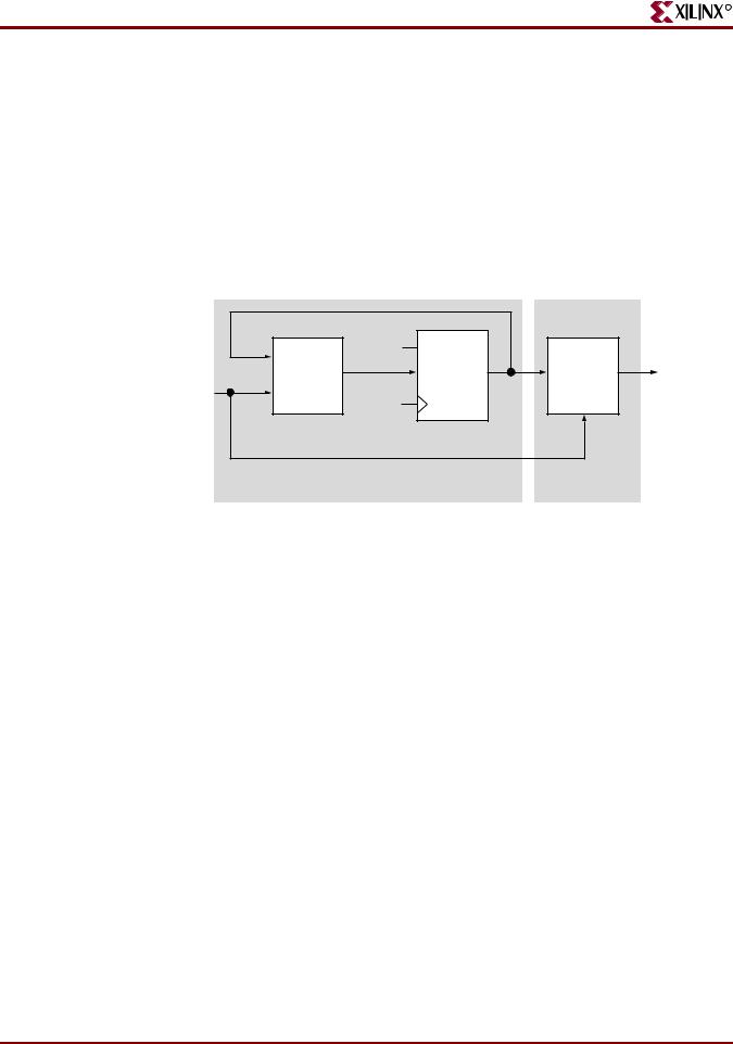
FSM With Two Processes
This section discusses FSM With Two Processes, and includes:
•“FSM With Two Processes Diagram.”
•“FSM With Two Processes Pin Descriptions”
•“FSM With Two Processes VHDL Coding Example”
•“FSM With Two Always Blocks Verilog Coding Example”
To eliminate a register from the outputs, remove all assignments outp <=… from the Clock synchronization section. This can be done by introducing two processes as shown in “FSM With Two Processes Diagram.”
|
Next |
RESET |
|
|
|
State |
Output |
Outputs |
|
|
State |
|||
|
Register |
Function |
||
|
|
|||
Inputs |
Function |
|
||
CLOCK |
|
|
||
|
|
|
|
|
|
Only for Mealy Machine |
|
|
PROCESS 1 |
PROCESS 2 |
|
|
|
|
X8986 |
|
|
Figure 2-76: FSM With Two Processes Diagram |
|
Table 2-93: FSM With Two Processes Pin Descriptions |
|
||
|
|
|
|
IO Pins |
|
Description |
|
|
|
|
|
clk |
|
Positive-Edge Clock |
|
|
|
|
|
reset |
|
Asynchronous Reset (Active High) |
|
|
|
|
|
x1 |
|
FSM Input |
|
|
|
|
|
outp |
|
FSM Output |
|
|
|
|
|
FSM With Two Processes VHDL Coding Example
--
-- State Machine with two processes.
--
library IEEE;
use IEEE.std_logic_1164.all; entity fsm_2 is
port ( clk, reset, x1 : IN std_logic;
outp |
: OUT std_logic); |
end entity; |
|
architecture beh1 of fsm_2 is
type state_type is (s1,s2,s3,s4); signal state: state_type ;
begin
248 |
www.xilinx.com |
XST User Guide |
10.1

R
Finite State Machines (FSMs) HDL Coding Techniques
process1: process (clk,reset) begin
if (reset ='1') then state <=s1; elsif (clk='1' and clk'Event) then
case state is
when s1 => if x1='1' then state <= s2;
else
state <= s3; end if;
when s2 => state <= s4; when s3 => state <= s4; when s4 => state <= s1;
end case; end if;
end process process1;
process2 : process (state) begin
case state is
when s1 => outp <= '1'; when s2 => outp <= '1'; when s3 => outp <= '0'; when s4 => outp <= '0';
end case;
end process process2;
end beh1;
FSM With Two Always Blocks Verilog Coding Example
//
// State Machine with two always blocks.
//
module v_fsm_2 (clk, reset, x1, outp);
input |
clk, reset, x1; |
output |
outp; |
reg |
outp; |
reg |
[1:0] state; |
parameter s1 = 2'b00; parameter s2 = 2'b01; parameter s3 = 2'b10; parameter s4 = 2'b11;
initial begin state = 2'b00;
end
always @(posedge clk or posedge reset) begin
if (reset) state <= s1;
else begin
case (state)
s1: if (x1==1'b1) state <= s2;
else
XST User Guide |
www.xilinx.com |
249 |
10.1
Chapter 2: XST HDL Coding Techniques
R
state <= s3; s2: state <= s4; s3: state <= s4; s4: state <= s1;
endcase
end
end
always @(state) begin
case (state)
s1: outp = 1'b1; s2: outp = 1'b1; s3: outp = 1'b0; s4: outp = 1'b0;
endcase
end
endmodule
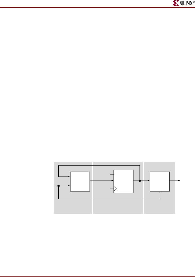
FSM With Three Processes
This section discusses FSM With Three Processes, and includes:
•“FSM With Three Processes Diagram.”
•“FSM With Three Processes Pin Descriptions”
•“FSM With Three Processes VHDL Coding Example”
•“FSM With Three Always Blocks Verilog Coding Example”
You can also separate the NEXT State function from the state register.
|
Next |
RESET |
|
|
|
State |
Output |
Outputs |
|
|
State |
|||
|
Register |
Function |
||
Inputs |
Function |
|
||
CLOCK |
|
|
||
|
|
|
|
|
Only for Mealy Machine |
|
PROCESS 1 |
PROCESS 2 |
PROCESS 3 |
X8987
Figure 2-77: FSM With Three Processes Diagram
Table 2-94: FSM With Three Processes Pin Descriptions
IO Pins |
Description |
|
|
clk |
Positive-Edge Clock |
|
|
reset |
Asynchronous Reset (Active High) |
|
|
250 |
www.xilinx.com |
XST User Guide |
10.1
R
Finite State Machines (FSMs) HDL Coding Techniques
Table 2-94: FSM With Three Processes Pin Descriptions
IO Pins |
Description |
|
|
x1 |
FSM Input |
|
|
outp |
FSM Output |
|
|
FSM With Three Processes VHDL Coding Example
--
-- State Machine with three processes.
--
library IEEE;
use IEEE.std_logic_1164.all; entity fsm_3 is
port ( clk, reset, x1 : IN std_logic;
outp |
: OUT std_logic); |
end entity; |
|
architecture beh1 of fsm_3 is
type state_type is (s1,s2,s3,s4); signal state, next_state: state_type ;
begin
process1: process (clk,reset) begin
if (reset ='1') then state <=s1;
elsif (clk='1' and clk'Event) then state <= next_state;
end if;
end process process1;
process2 : process (state, x1) begin
case state is
when s1 => if x1='1' then next_state <= s2;
else
next_state <= s3; end if;
when s2 => next_state <= s4; when s3 => next_state <= s4; when s4 => next_state <= s1;
end case;
end process process2;
process3 : process (state) begin
case state is
when s1 => outp <= '1'; when s2 => outp <= '1'; when s3 => outp <= '0'; when s4 => outp <= '0';
end case;
end process process3;
end beh1;
XST User Guide |
www.xilinx.com |
251 |
10.1

Chapter 2: XST HDL Coding Techniques
FSM With Three Always Blocks Verilog Coding Example
//
// State Machine with three always blocks.
//
module v_fsm_3 (clk, reset, x1, outp); input clk, reset, x1;
output outp; reg outp;
reg [1:0] state;
reg [1:0] next_state;
parameter s1 = 2'b00; parameter s2 = 2'b01; parameter s3 = 2'b10; parameter s4 = 2'b11;
initial begin state = 2'b00;
end
always @(posedge clk or posedge reset) begin
if (reset) state <= s1; else state <= next_state;
end
always @(state or x1) begin
case (state)
s1: if (x1==1'b1) next_state = s2;
else
next_state = s3; s2: next_state = s4; s3: next_state = s4; s4: next_state = s1;
endcase
end
always @(state) begin
case (state)
s1: outp = 1'b1; s2: outp = 1'b1; s3: outp = 1'b0; s4: outp = 1'b0;
endcase
end
endmodule
R
252 |
www.xilinx.com |
XST User Guide |
|
|
10.1 |