


R
Multiplexers HDL Coding Techniques
16-Bit Dynamic Shift Register With Positive-Edge Clock, Serial In and Serial Out Verilog Coding Example
//
// 16-bit dynamic shift register.
//
module v_dynamic_shift_registers_1 (Q,CE,CLK,D,A); input CLK, D, CE;
input [3:0] A; output Q;
reg [15:0] data;
assign Q = data[A];
always @(posedge CLK) begin
if (CE == 1'b1)
data <= {data[14:0], D};
end
endmodule
Multiplexers HDL Coding Techniques
This section discusses Multiplexers HDL Coding Techniques, and includes:
•“About Multiplexers”
•“Multiplexers Case Statements”
•“Multiplexers Log File”
•“Multiplexers Related Constraints”
•“Multiplexers Coding Examples”
About Multiplexers
XST supports different description styles for multiplexers (MUXs), such as If-Then- Else or Case. When writing MUXs, pay special attention in order to avoid common traps. For example, if you describe a MUX using a Case statement, and you do not specify all values of the selector, the result may be latches instead of a multiplexer. Writing MUXs you can also use don't cares to describe selector values.
During the Macro Inference step, XST makes a decision to infer or not infer the MUXs. For example, if the MUX has several inputs that are the same, then XST can decide not to infer it. If you do want to infer the MUX, force XST by using the MUX_EXTRACT constraint.
If you use Verilog, remember that Verilog Case statements can be full or not full, and they can also be parallel or not parallel. A Case statement is:
•FULL if all possible branches are specified
•PARALLEL if it does not contain branches that can be executed simultaneously
XST User Guide |
www.xilinx.com |
87 |
10.1

Chapter 2: XST HDL Coding Techniques
R
Multiplexers Case Statements
This section discusses Multiplexers Case Statements, and includes:
•“Multiplexers Case Statement Examples”
•“Verilog Case Implementation Style Parameter”
•“Verilog Case Statement Resources”
Multiplexers Case Statement Examples
Following are three examples of Case statements:
•“Full and Parallel Case Statement Example”
•“Not Full But Parallel Case Statement Example”
•“Neither Full Nor Parallel Case Statement Example”
Full and Parallel Case Statement Example
module full (sel, i1, i2, i3, i4, o1); input [1:0] sel;
input [1:0] i1, i2, i3, i4; output [1:0] o1;
reg [1:0] o1;
always @(sel or i1 or i2 or i3 or i4) begin
case (sel)
2'b00: o1 = i1; 2'b01: o1 = i2; 2'b10: o1 = i3; 2'b11: o1 = i4; endcase
end endmodule
Not Full But Parallel Case Statement Example
module notfull (sel, i1, i2, i3, o1); input [1:0] sel;
input [1:0] i1, i2, i3; output [1:0] o1;
reg [1:0] o1;
always @(sel or i1 or i2 or i3) begin
case (sel)
2'b00: o1 = i1; 2'b01: o1 = i2; 2'b10: o1 = i3;
endcase end
endmodule
88 |
www.xilinx.com |
XST User Guide |
|
|
10.1 |

R
Multiplexers HDL Coding Techniques
Neither Full Nor Parallel Case Statement Example
module notfull_notparallel (sel1, sel2, i1, i2, o1); input [1:0] sel1, sel2;
input [1:0] i1, i2; output [1:0] o1;
reg [1:0] o1;
always @(sel1 or sel2) begin
case (2'b00) sel1: o1 = i1; sel2: o1 = i2;
endcase end
endmodule
XST automatically determines the characteristics of the Case statements and generates logic using multiplexers, priority encoders, and latches that best implement the exact behavior of the Case statement.
Verilog Case Implementation Style Parameter
This characterization of the Case statements can be guided or modified by using the Case Implementation Style parameter. For more information, see “XST Design Constraints.” Accepted values for this parameter are none, full, parallel, and full-parallel.
•If none (default) is used, XST implements the exact behavior of the Case statements.
•If full is used, XST considers that Case statements are complete and avoids latch creation.
•If parallel is used, XST considers that the branches cannot occur in parallel and does not use a priority encoder.
•If full-parallel is used, XST considers that Case statements are complete and that the branches cannot occur in parallel, therefore saving latches and priority encoders.
Verilog Case Statement Resources
Table 2-33, “Verilog Case Statement Resources,” indicates the resources used to synthesize the “Multiplexers Case Statement Examples” using the four Case Implementation Styles. The term resources means the functionality. For example, if you code the Case statement neither full nor parallel with Case Implementation Style set to none, from the functionality point of view, XST implements a priority encoder + latch. But, it does not inevitably mean that XST infers the priority encoder during the Macro Recognition step.
Table 2-33: |
Verilog Case Statement Resources |
|
|||
|
|
|
|
|
|
Parameter Value |
|
Case Implementation |
|||
|
|
|
|||
Full |
Not Full |
Neither Full nor Parallel |
|||
|
|
||||
|
|
|
|
|
|
none |
|
MUX |
Latch |
Priority Encoder + Latch |
|
|
|
|
|
|
|
parallel |
|
MUX |
Latch |
Latch |
|
|
|
|
|
|
|
full |
|
MUX |
MUX |
Priority Encoder |
|
|
|
|
|
|
|
full-parallel |
|
MUX |
MUX |
MUX |
|
|
|
|
|
|
|
XST User Guide |
www.xilinx.com |
89 |
10.1

Chapter 2: XST HDL Coding Techniques
R
Specifying full, parallel or full-parallel may result in an implementation with a behavior that may differ from the behavior of the initial model.
Multiplexers Log File
The XST log file reports the type and size of recognized MUXs during the Macro
Recognition step.
...
Synthesizing Unit <mux>.
Related source file is multiplexers_1.vhd. Found 1-bit 4-to-1 multiplexer for signal <o>. Summary:
inferred 1 Multiplexer(s).
Unit <mux> synthesized. |
|
============================= |
|
HDL Synthesis Report |
|
Macro Statistics |
|
# Multiplexers |
: 1 |
1-bit 4-to-1 multiplexer |
: 1 |
============================== |
|
... |
|
Multiplexers Related Constraints
•“Mux Extraction (MUX_EXTRACT)”
•“Mux Style (MUX_STYLE)”
•“Enumerated Encoding (ENUM_ENCODING)”
Multiplexers Coding Examples
This section gives the following Multiplexers examples:
•“4-to-1 1-Bit MUX Using IF Statement”
•“4-to-1 1-Bit MUX Using Case Statement”
•“4-to-1 1-Bit MUX Using Tristate Buffers”
•“No 4-to-1 MUX (3-to-1 1-Bit MUX With 1-Bit Latch)”
The coding examples in this section are accurate as of the date of publication. Download updates from ftp://ftp.xilinx.com/pub/documentation/misc/examples_v9.zip.
4-to-1 1-Bit MUX Using IF Statement
This section discusses 4-to-1 1-Bit MUX Using IF Statement, and includes:
•“4-to-1 1-Bit MUX Using IF Statement Diagram”
•“4-to-1 1-Bit MUX Using IF Statement Pin Descriptions”
•“4-to-1 1-Bit MUX Using IF Statement VHDL Coding Example”
•“4-to-1 1-Bit MUX Using IF Statement Verilog Coding Example”
90 |
www.xilinx.com |
XST User Guide |
|
|
10.1 |
R
Multiplexers HDL Coding Techniques
|
|
A |
|
|
|
|
|
|
|
|
|
|
|
|
|
|
|
||
|
|
B |
|
|
|
|
|
O |
|
|
|
|
|
|
|||||
|
|
C |
|
|
|
|
|
|
|
|
|
|
|
|
|
|
|
||
|
|
D |
|
|
|
|
|
|
|
|
|
|
2 |
|
|
|
|||
|
|
S |
|
|
|
|
|
||
|
|
|
|
|
|
|
|||
|
|
|
|
|
|
X10543 |
|||
|
|
|
|
|
|
||||
|
|
|
|
|
|
|
|
||
|
Figure 2-31: 4-to-1 1-Bit MUX Using IF Statement Diagram |
||||||||
Table 2-34: 4-to-1 1-Bit MUX Using IF Statement Pin Descriptions |
|||||||||
|
|
|
|
|
|
|
|
|
|
IO Pins |
|
Description |
|
|
|
|
|
||
|
|
|
|
|
|
|
|
|
|
a, b, c, d |
|
Data Inputs |
|
|
|
|
|
||
|
|
|
|
|
|
|
|
|
|
s |
|
MUX Selector |
|
|
|
|
|
||
|
|
|
|
|
|
|
|
|
|
o |
|
Data Output |
|
|
|
|
|
||
|
|
|
|
|
|
|
|
|
|
4-to-1 1-Bit MUX Using IF Statement VHDL Coding Example
--
-- 4-to-1 1-bit MUX using an If statement.
--
library ieee;
use ieee.std_logic_1164.all;
entity multiplexers_1 is
port (a, b, c, d : in std_logic;
s : in std_logic_vector (1 downto 0); o : out std_logic);
end multiplexers_1;
architecture archi of multiplexers_1 is begin
process (a, b, c, d, s) begin
if (s = "00") then o <= a; elsif (s = "01") then o <= b; elsif (s = "10") then o <= c; else o <= d;
end if; end process;
end archi;
XST User Guide |
www.xilinx.com |
91 |
10.1
Chapter 2: XST HDL Coding Techniques
4-to-1 1-Bit MUX Using IF Statement Verilog Coding Example
//
// 4-to-1 1-bit MUX using an If statement.
//
module v_multiplexers_1 (a, b, c, d, s, o); input a,b,c,d;
input [1:0] s; output o;
reg o;
always @(a or b or c or d or s) begin
if (s == 2'b00) o = a; else if (s == 2'b01) o = b; else if (s == 2'b10) o = c; else o = d;
end endmodule
R
4-to-1 1-Bit MUX Using Case Statement
This section discusses 4-to-1 1-Bit MUX Using Case Statement, and includes:
•“4-to-1 1-Bit MUX Using Case Statement Diagram”
•“4-to-1 1-Bit MUX Using Case Statement Pin Descriptions”
•“4-to-1 1-Bit MUX Using Case Statement VHDL Coding Example”
•“4-to-1 1-Bit MUX Using Case Statement Verilog Coding Example”
|
|
A |
|
|
|
|
|
|
|
|
|
|
|
|
|
||
|
|
B |
|
|
|
|
O |
|
|
|
|
|
|||||
|
|
C |
|
|
|
|
|
|
|
|
|
|
|
|
|
||
|
|
D |
|
|
|
|
|
|
|
|
2 |
|
|
|
|||
|
|
S |
|
|
|
|
||
|
|
|
|
|
|
|||
|
|
|
|
|
|
X10543 |
||
|
|
|
|
|
|
|||
|
|
|
|
|
|
|
||
|
Figure 2-32: 4-to-1 1-Bit MUX Using Case Statement Diagram |
|||||||
Table 2-35: 4-to-1 1-Bit MUX Using Case Statement Pin Descriptions |
||||||||
|
|
|
|
|
|
|
|
|
IO Pins |
|
Description |
|
|
|
|
|
|
|
|
|
|
|
|
|
|
|
a, b, c, d |
|
Data Inputs |
|
|
|
|
|
|
|
|
|
|
|
|
|
|
|
92 |
www.xilinx.com |
XST User Guide |
|
|
10.1 |

R
Multiplexers HDL Coding Techniques
Table 2-35: 4-to-1 1-Bit MUX Using Case Statement Pin Descriptions (Cont’d)
IO Pins |
Description |
|
|
s |
MUX Selector |
|
|
o |
Data Output |
|
|
4-to-1 1-Bit MUX Using Case Statement VHDL Coding Example
--
-- 4-to-1 1-bit MUX using a Case statement.
--
library ieee;
use ieee.std_logic_1164.all;
entity multiplexers_2 is
port (a, b, c, d : in std_logic;
s : in std_logic_vector (1 downto 0); o : out std_logic);
end multiplexers_2;
architecture archi of multiplexers_2 is begin
process (a, b, c, d, s) begin
case s is
when "00" => o <= a; when "01" => o <= b; when "10" => o <= c; when others => o <= d;
end case; end process;
end archi;
4-to-1 1-Bit MUX Using Case Statement Verilog Coding Example
//
// 4-to-1 1-bit MUX using a Case statement.
//
module v_multiplexers_2 (a, b, c, d, s, o); input a,b,c,d;
input [1:0] s; output o;
reg o;
always @(a or b or c or d or s) begin
case (s)
2'b00 : o = a; 2'b01 : o = b; 2'b10 : o = c; default : o = d;
endcase
end endmodule
XST User Guide |
www.xilinx.com |
93 |
10.1
Chapter 2: XST HDL Coding Techniques
R
4-to-1 1-Bit MUX Using Tristate Buffers
This section discusses 4-to-1 1-Bit MUX Using Tristate Buffers, and includes:
•“4-to-1 1-Bit MUX Using Tristate Buffers Diagram”
•“4-to-1 1-Bit MUX Using Tristate Buffers Pin Descriptions”
•“4-to-1 1-Bit MUX Using Tristate Buffers VHDL Coding Example”
•“4-to-1 1-Bit MUX Using Tristate Buffers Verilog Coding Example”
|
|
|
|
|
|
|
|
|
|
|
|
|
|
|
|
|
|
|
|
|
|
|
|
|
|
|
|
|
O |
S[3] |
|
|
|
|
S[2] |
|
|
|
|
|
S[1] |
|
|
|
|
|
|
S[0] |
|
|
|
|
|
|
|||||
|
|
|
|
|
|
|
|
|
|
|
|
|
|
|
|
|
|
|
|||||||||||
|
|
|
|
|
|
|
|
|
|
|
|
||||||||||||||||||
A |
|
|
|
|
|
B |
|
|
|
|
|
|
C |
|
|
|
|
|
|
D |
|
|
|
|
|
|
X10544 |
||
|
|
|
|
|
|
||||||||||||||||||||||||
|
|
|
|
|
|
|
|
|
|
|
|
|
|
||||||||||||||||
|
|
|
|
|
|
|
|
|
|
|
|
|
|
|
|
|
|
|
|
|
|
|
|
|
|
|
|
||
Figure 2-33: 4-to-1 1-Bit MUX Using Tristate Buffers Diagram |
|||||||||||||||||||||||||||||
Table 2-36: 4-to-1 1-Bit MUX Using Tristate Buffers Pin Descriptions |
|||||||||||||||||||||||||||||
|
|
|
|
|
|
|
|
|
|
|
|
|
|
|
|
|
|
|
|
|
|
|
|
|
|
|
|
|
|
IO Pins |
Description |
|
|
|
|
|
|
|
|
|
|
|
|
|
|
|
|
|
|
|
|
||||||||
|
|
|
|
|
|
|
|
|
|
|
|
|
|
|
|
|
|
|
|
|
|
|
|
|
|
|
|
|
|
a, b, c, d |
Data Inputs |
|
|
|
|
|
|
|
|
|
|
|
|
|
|
|
|
|
|
|
|
||||||||
|
|
|
|
|
|
|
|
|
|
|
|
|
|
|
|
|
|
|
|
|
|
|
|
|
|
|
|
|
|
s |
MUX Selector |
|
|
|
|
|
|
|
|
|
|
|
|
|
|
|
|
|
|
|
|
||||||||
|
|
|
|
|
|
|
|
|
|
|
|
|
|
|
|
|
|
|
|
|
|
|
|
|
|
|
|
|
|
o |
Data Output |
|
|
|
|
|
|
|
|
|
|
|
|
|
|
|
|
|
|
|
|
||||||||
|
|
|
|
|
|
|
|
|
|
|
|
|
|
|
|
|
|
|
|
|
|
|
|
|
|
|
|
|
|
4-to-1 1-Bit MUX Using Tristate Buffers VHDL Coding Example
--
-- 4-to-1 1-bit MUX using tristate buffers.
--
library ieee;
use ieee.std_logic_1164.all;
entity multiplexers_3 is
port (a, b, c, d : in std_logic;
s : in std_logic_vector (3 downto 0); o : out std_logic);
end multiplexers_3;
architecture archi of multiplexers_3 is begin
o <= a when (s(0)='0') else 'Z'; o <= b when (s(1)='0') else 'Z'; o <= c when (s(2)='0') else 'Z'; o <= d when (s(3)='0') else 'Z';
end archi;
94 |
www.xilinx.com |
XST User Guide |
|
|
10.1 |

R
Multiplexers HDL Coding Techniques
4-to-1 1-Bit MUX Using Tristate Buffers Verilog Coding Example
//
// 4-to-1 1-bit MUX using tristate buffers.
//
module v_multiplexers_3 (a, b, c, d, s, o); input a,b,c,d;
input [3:0] s; output o;
assign o = s[3] ? a :1'bz; assign o = s[2] ? b :1'bz; assign o = s[1] ? c :1'bz; assign o = s[0] ? d :1'bz;
endmodule
No 4-to-1 MUX (3-to-1 1-Bit MUX With 1-Bit Latch)
This section discusses No 4-to-1 MUX (3-to-1 1-Bit MUX With 1-Bit Latch), and includes:
•“XST HDL Advisor Message Example”
•“3-to-1 1-Bit MUX With 1-Bit Latch Diagram”
•“3-to-1 1-Bit MUX With 1-Bit Latch Pin Descriptions”
•“3-to-1 1-Bit MUX With 1-Bit Latch VHDL Coding Example”
•“3-to-1 1-Bit MUX With 1-Bit Latch Verilog Coding Example”
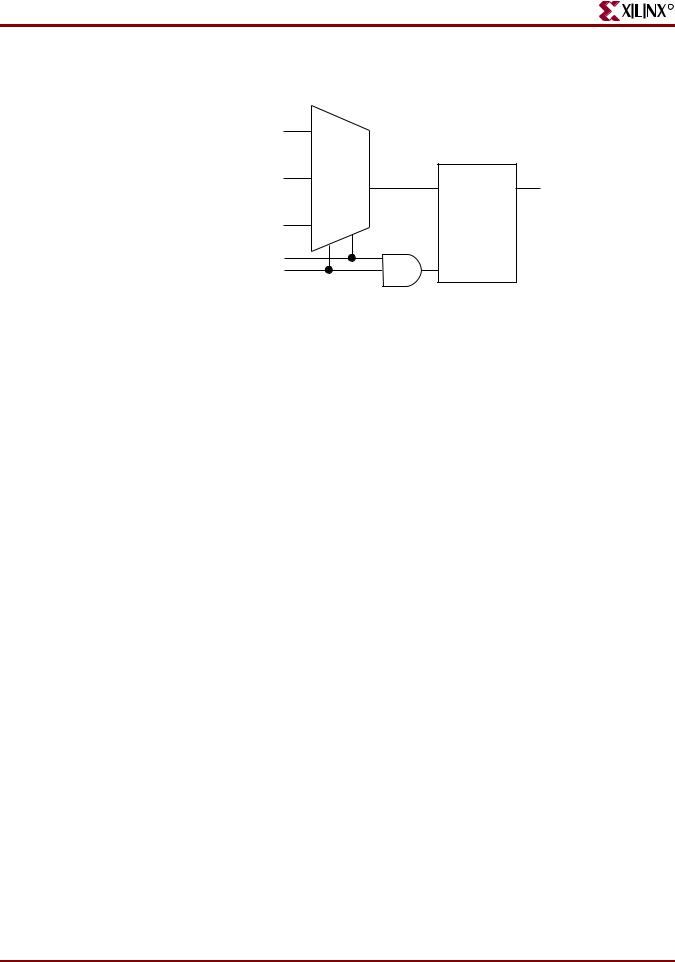
XST HDL Advisor Message Example
The following XST HDL Advisor Message does not generate a 4-to-1 1-bit MUX, but rather a 3-to-1 MUX With 1-Bit Latch. Since not all selector values were described in the If statement, XST assumes that, for the s=11 case, o keeps its old value, and that a memory element is needed.
WARNING:Xst:737 - Found 1-bit latch for signal <o1>.
INFO:Xst - HDL ADVISOR - Logic functions respectively driving the data and gate enable inputs of this latch share common terms. This situation will potentially lead to setup/hold violations and, as a result, to simulation problems. This situation may come from an incomplete case statement (all selector values are not covered). You should carefully review if it was in your intentions to describe such a latch
XST User Guide |
www.xilinx.com |
95 |
10.1
Chapter 2: XST HDL Coding Techniques
R
.
A |
|
B |
LD |
|
O |
C |
|
S[1] |
G |
S[0] |
|
|
X10545 |
Figure 2-34: 3-to-1 1-Bit MUX With 1-Bit Latch Diagram
Table 2-37: 3-to-1 1-Bit MUX With 1-Bit Latch Pin Descriptions
IO Pins |
Description |
|
|
a, b, c |
Data Inputs |
|
|
s |
MUX Selector |
|
|
o |
Data Output |
|
|
3-to-1 1-Bit MUX With 1-Bit Latch VHDL Coding Example
--
-- 3-to-1 1-bit MUX with a 1-bit latch.
--
library ieee;
use ieee.std_logic_1164.all;
entity multiplexers_4 is
port (a, b, c: in std_logic;
s : in std_logic_vector (1 downto 0); o : out std_logic);
end multiplexers_4;
architecture archi of multiplexers_4 is begin
process (a, b, c, s) begin
if (s = "00") then o <= a; elsif (s = "01") then o <= b; elsif (s = "10") then o <= c; end if;
end process; end archi;
96 |
www.xilinx.com |
XST User Guide |
10.1