


R
Registers HDL Coding Techniques
Registers HDL Coding Techniques
This section discusses Registers HDL Coding Techniques, and includes:
•“About Registers”
•“Registers Log File”
•“Registers Related Constraints”
•“Registers Coding Examples”
About Registers
XST recognizes flip-flops with the following control signals:
•Asynchronous Set/Reset
•Synchronous Set/Reset
•Clock Enable
For more information, see “Specifying INIT and RLOC.”
Registers Log File
The XST log file reports the type and size of recognized flip-flops during the Macro
Recognition step.
...
===============================================================
* HDL Synthesis *
===============================================================
Synthesizing Unit <registers_5>.
Related source |
file is "registers_5.vhd". |
Found 4-bit register for signal <Q>. |
|
Summary: |
|
inferred |
4 D-type flip-flop(s). |
Unit <registers_5> |
synthesized. |
===============================================================
HDL Synthesis Report
Macro Statistics |
|
|
# Registers |
: |
1 |
4-bit register |
: |
1 |
===============================================================
===============================================================
* Advanced HDL Synthesis *
===============================================================
===============================================================
Advanced HDL Synthesis Report
Macro Statistics |
|
|
# Registers |
: |
4 |
Flip-Flops/Latches |
: |
4 |
===============================================================
...
XST User Guide |
www.xilinx.com |
25 |
10.1
Chapter 2: XST HDL Coding Techniques
R
With the introduction of new device families such as Virtex™-4, XST may optimize different slices of the same register in different ways. For example, XST may push a part of a register into a DSP48 block, while another part may be implemented on slices, or even become a part of a shift register. XST reports the total number of FF bits in the design in the HDL Synthesis Report after the Advanced HDL Synthesis step.
Registers Related Constraints
•“Pack I/O Registers Into IOBs (IOB)”
•“Register Duplication (REGISTER_DUPLICATION)”
•“Equivalent Register Removal (EQUIVALENT_REGISTER_REMOVAL)”
•“Register Balancing (REGISTER_BALANCING)”
Registers Coding Examples
This section gives the following Registers examples:
•“Flip-Flop With Positive-Edge Clock”
•“Flip-Flop With Negative-Edge Clock and Asynchronous Reset”
•“Flip-Flop With Positive-Edge Clock and Synchronous Set”
•“Flip-Flop With Positive-Edge Clock and Clock Enable”
•“4-Bit Register With Positive-Edge Clock, Asynchronous Set, and Clock Enable”
The coding examples in this section are accurate as of the date of publication. Download updates from ftp://ftp.xilinx.com/pub/documentation/misc/examples_v9.zip.
Flip-Flop With Positive-Edge Clock
This section discusses Flip-Flop With Positive-Edge Clock, and includes:
•“Flip-Flop With Positive-Edge Clock Diagram”
•“Flip-Flop With Positive-Edge Clock Pin Descriptions”
•“Flip-Flop With Positive Edge Clock VHDL Coding Example”
•“Flip-Flop With Positive-Edge Clock Verilog Coding Example”
Figure 2-1: Flip-Flop With Positive-Edge Clock Diagram
26 |
www.xilinx.com |
XST User Guide |
|
|
10.1 |

R
Registers HDL Coding Techniques
Table 2-3: |
Flip-Flop With Positive-Edge Clock Pin Descriptions |
|
|
|
|
IO Pins |
|
Description |
|
|
|
D |
|
Data Input |
|
|
|
C |
|
Positive-Edge Clock |
|
|
|
Q |
|
Data Output |
|
|
|
Flip-Flop With Positive Edge Clock VHDL Coding Example
--
-- Flip-Flop with Positive-Edge Clock
--
library ieee;
use ieee.std_logic_1164.all;
entity registers_1 is port(C, D : in std_logic;
Q : out std_logic); end registers_1;
architecture archi of registers_1 is begin
process (C) begin
if (C'event and C='1') then Q <= D;
end if; end process;
end archi;
When using VHDL for a positive-edge clock, instead of using:
if (C'event and C='1') then
you can also use:
if (rising_edge(C)) then
Flip-Flop With Positive-Edge Clock Verilog Coding Example
//
// Flip-Flop with Positive-Edge Clock
//
module v_registers_1 (C, D, Q); input C, D;
output Q; reg Q;
always @(posedge C) begin
Q <= D;
end
endmodule
XST User Guide |
www.xilinx.com |
27 |
10.1

Chapter 2: XST HDL Coding Techniques
R
Flip-Flop With Negative-Edge Clock and Asynchronous Reset
This section discusses Flip-Flop With Negative-Edge Clock and Asynchronous Reset, and includes:
•“Flip-Flop With Negative-Edge Clock and Asynchronous Reset Diagram”
•“Flip-Flop With Negative-Edge Clock and Asynchronous Reset Pin Descriptions”
•“Flip-Flop With Negative-Edge Clock and Asynchronous Reset VHDL Coding Example”
•“Flip-Flop With Negative-Edge Clock and Asynchronous Reset Verilog Coding Example”
D |
FDC_1 |
Q |
|
|
|
||
C |
|
|
|
CLR |
|
|
X3847 |
|
|
||
|
|
|
|
Figure 2-2: Flip-Flop With Negative-Edge Clock and Asynchronous Reset Diagram
Table 2-4: Flip-Flop With Negative-Edge Clock and Asynchronous Reset Pin
Descriptions
IO Pins |
Description |
|
|
D |
Data Input |
|
|
C |
Negative-Edge Clock |
|
|
CLR |
Asynchronous Reset (Active High) |
|
|
Q |
Data Output |
|
|
Flip-Flop With Negative-Edge Clock and Asynchronous Reset VHDL Coding Example
--
-- Flip-Flop with Negative-Edge Clock and Asynchronous Reset
--
library ieee;
use ieee.std_logic_1164.all;
entity registers_2 |
is |
port(C, D, CLR |
: in std_logic; |
Q |
: out std_logic); |
end registers_2; |
|
architecture archi |
of registers_2 is |
begin |
|
process (C, CLR) begin
28 |
www.xilinx.com |
XST User Guide |
|
|
10.1 |

R
Registers HDL Coding Techniques
if (CLR = '1')then Q <= '0';
elsif (C'event and C='0')then Q <= D;
end if; end process;
end archi;
Flip-Flop With Negative-Edge Clock and Asynchronous Reset Verilog Coding Example
//
// Flip-Flop with Negative-Edge Clock and Asynchronous Reset
//
module v_registers_2 (C, D, CLR, Q); input C, D, CLR;
output Q; reg Q;
always @(negedge C or posedge CLR) begin
if (CLR)
Q <= 1'b0; else
Q <= D;
end
endmodule
Flip-Flop With Positive-Edge Clock and Synchronous Set
This section discusses Flip-Flop With Positive-Edge Clock and Synchronous Set, and includes:
•“Flip-Flop With Positive-Edge Clock and Synchronous Set Diagram”
•“Flip-Flop With Positive-Edge Clock and Synchronous Set Pin Descriptions”
•“Flip-Flop With Positive-Edge Clock and Synchronous Set VHDL Coding Example”
•“Flip-Flop With Positive-Edge Clock and Synchronous Set Verilog Coding Example”
S |
|
|
|
|
|
|
|
|
|
D |
FDS |
Q |
||
|
|
|||
C |
|
|
|
|
|
|
|
X3722 |
|
|
|
|
||
Figure 2-3: Flip-Flop With Positive-Edge Clock and Synchronous Set Diagram
XST User Guide |
www.xilinx.com |
29 |
10.1

Chapter 2: XST HDL Coding Techniques
R
Table 2-5: Flip-Flop With Positive-Edge Clock and Synchronous Set Pin Descriptions
IO Pins |
Description |
|
|
D |
Data Input |
|
|
C |
Positive-Edge Clock |
|
|
S |
Synchronous Set (Active High) |
|
|
Q |
Data Output |
|
|
Flip-Flop With Positive-Edge Clock and Synchronous Set VHDL Coding Example
--
-- Flip-Flop with Positive-Edge Clock and Synchronous Set
--
library ieee;
use ieee.std_logic_1164.all;
entity registers_3 is
port(C, D, S : |
in |
std_logic; |
|
Q |
: |
out |
std_logic); |
end registers_3;
architecture archi of registers_3 is begin
process (C) begin
if (C'event and C='1') then if (S='1') then
Q <= '1';
else
Q <= D; end if;
end if; end process;
end archi;
Flip-Flop With Positive-Edge Clock and Synchronous Set Verilog Coding Example
//
// Flip-Flop with Positive-Edge Clock and Synchronous Set
//
module v_registers_3 (C, D, S, Q); input C, D, S;
output Q; reg Q;
always @(posedge C) begin
if (S)
Q <= 1'b1; else
Q <= D;
end
endmodule
30 |
www.xilinx.com |
XST User Guide |
|
|
10.1 |
R
Registers HDL Coding Techniques
Flip-Flop With Positive-Edge Clock and Clock Enable
This section discusses Flip-Flop With Positive-Edge Clock and Clock Enable, and includes:
•“Flip-Flop With Positive-Edge Clock and Clock Enable Diagram”
•“Flip-Flop With Positive-Edge Clock and Clock Enable Pin Descriptions”
•“Flip-Flop With Positive-Edge Clock and Clock Enable VHDL Coding Example”
•“Flip-Flop With Positive-Edge Clock and Clock Enable Verilog Coding Example”
FDE
D
CE |
Q |
C
X8361
Figure 2-4: Flip-Flop With Positive-Edge Clock and Clock Enable Diagram
Table 2-6: Flip-Flop With Positive-Edge Clock and Clock Enable Pin Descriptions
IO Pins |
Description |
|
|
D |
Data Input |
|
|
C |
Positive-Edge Clock |
|
|
CE |
Clock Enable (Active High) |
|
|
Q |
Data Output |
|
|
Flip-Flop With Positive-Edge Clock and Clock Enable VHDL Coding Example
--
-- Flip-Flop with Positive-Edge Clock and Clock Enable
--
library ieee;
use ieee.std_logic_1164.all;
entity registers_4 is
port(C, D, CE : in std_logic;
Q : out std_logic); end registers_4;
architecture archi of registers_4 is begin
process (C) begin
if (C'event and C='1') then if (CE='1') then
Q <= D; end if;
end if; end process;
end archi;
XST User Guide |
www.xilinx.com |
31 |
10.1

Chapter 2: XST HDL Coding Techniques
Flip-Flop With Positive-Edge Clock and Clock Enable Verilog Coding Example
//
// Flip-Flop with Positive-Edge Clock and Clock Enable
//
module v_registers_4 (C, D, CE, Q); input C, D, CE;
output Q; reg Q;
always @(posedge C) begin
if (CE)
Q <= D;
end
endmodule
4-Bit Register With Positive-Edge Clock, Asynchronous Set, and Clock
Enable
R
This section discusses 4-Bit Register With Positive-Edge Clock, Asynchronous Set, and Clock Enable, and includes:
•“Flip-Flop With Positive-Edge Clock and Clock Enable Diagram”
•“4-Bit Register With Positive-Edge Clock, Asynchronous Set, and Clock Enable Pin Descriptions”
•“4-Bit Register With Positive-Edge Clock, Asynchronous Set, and Clock Enable VHDL Coding Example”
•“4-Bit Register With Positive-Edge Clock, Asynchronous Set, and Clock Enable Verilog Coding Example”
PRE
|
|
|
|
D |
FDPE |
Q |
|
|
|
||
CE |
|
|
|
C |
|
|
|
|
|
|
|
X3721
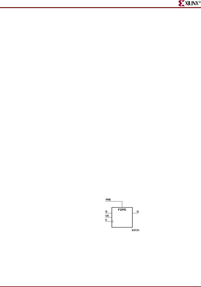
Figure 2-5: 4-Bit Register With Positive-Edge Clock, Asynchronous Set, and Clock
Enable Diagram
Table 2-7: 4-Bit Register With Positive-Edge Clock, Asynchronous Set, and Clock Enable Pin Descriptions
IO Pins |
Description |
|
|
D |
Data Input |
|
|
C |
Positive-Edge Clock |
|
|
PRE |
Asynchronous Set (Active High) |
|
|
32 |
www.xilinx.com |
XST User Guide |
|
|
10.1 |

R
Registers HDL Coding Techniques
Table 2-7: 4-Bit Register With Positive-Edge Clock, Asynchronous Set, and Clock Enable Pin Descriptions (Cont’d)
IO Pins |
Description |
|
|
CE |
Clock Enable (Active High) |
|
|
Q |
Data Output |
|
|
4-Bit Register With Positive-Edge Clock, Asynchronous Set, and Clock Enable VHDL Coding Example
--
-- 4-bit Register with Positive-Edge Clock, Asynchronous Set and Clock Enable
--
library ieee;
use ieee.std_logic_1164.all;
entity registers_5 is
port(C, CE, PRE : in std_logic;
D : in std_logic_vector (3 downto 0);
Q : out std_logic_vector (3 downto 0)); end registers_5;
architecture archi of registers_5 is begin
process (C, PRE) begin
if (PRE='1') then Q <= "1111";
elsif (C'event and C='1')then if (CE='1') then
Q <= D; end if;
end if; end process;
end archi;
4-Bit Register With Positive-Edge Clock, Asynchronous Set, and Clock Enable Verilog Coding Example
//
// 4-bit Register with Positive-Edge Clock, Asynchronous Set and Clock Enable
//
module v_registers_5 (C, D, CE, PRE, Q);
input |
C, CE, PRE; |
input |
[3:0] D; |
output |
[3:0] Q; |
reg |
[3:0] Q; |
always |
@(posedge C or posedge PRE) |
begin |
|
if |
(PRE) |
XST User Guide |
www.xilinx.com |
33 |
10.1