


R
Dynamic Shift Registers HDL Coding Techniques
end process;
PO <= tmp;
end archi;
8-Bit Shift-Left/Shift-Right Register With Positive-Edge Clock, Serial In and Parallel Out Verilog Coding Example
//
//8-bit Shift-Left/Shift-Right Register with Positive-Edge Clock,
//Serial In, and Parallel Out
//
module v_shift_registers_8 (C, SI, LEFT_RIGHT, PO); input C,SI,LEFT_RIGHT;
output [7:0] PO; reg [7:0] tmp;
always @(posedge C) begin
if (LEFT_RIGHT==1'b0) tmp <= {tmp[6:0], SI};
else
tmp <= {SI, tmp[7:1]};
end
assign PO = tmp;
endmodule
Dynamic Shift Registers HDL Coding Techniques
This section discusses Dynamic Shift Registers HDL Coding Techniques, and includes:
•“About Dynamic Shift Registers”
•“Dynamic Shift Registers Log File”
•“Dynamic Shift Registers Related Constraints”
•“Dynamic Shift Registers Coding Examples”
About Dynamic Shift Registers
XST can infer Dynamic Shift Registers. Once a dynamic shift register has been identified, its characteristics are handed to the XST macro generator for optimal implementation using the primitives shown in Table 2-31, “Implementing Dynamic Shift Registers.”
Table 2-31: Implementing Dynamic Shift Registers
|
SRL16 |
SRL16E |
SRLC16 |
SRLC16E |
SRLC32E |
|
|
|
|
|
|
Virtex, Virtex-E |
Yes |
Yes |
No |
No |
No |
|
|
|
|
|
|
Spartan-II, Spartan-IIE |
Yes |
Yes |
No |
No |
No |
|
|
|
|
|
|
Virtex-II, Virtex-II Pro |
Yes |
Yes |
Yes |
Yes |
No |
|
|
|
|
|
|
XST User Guide |
www.xilinx.com |
83 |
10.1

Chapter 2: XST HDL Coding Techniques
R
|
SRL16 |
SRL16E |
SRLC16 |
SRLC16E |
SRLC32E |
|
|
|
|
|
|
Spartan-3, Spartan-3-E, Spartan-3A |
Yes |
Yes |
Yes |
Yes |
No |
|
|
|
|
|
|
Virtex-4 |
Yes |
Yes |
Yes |
Yes |
No |
|
|
|
|
|
|
Virtex-5 |
Yes |
Yes |
Yes |
Yes |
Yes |
|
|
|
|
|
|
Dynamic Shift Registers Log File
The recognition of dynamic shift registers happens in the Advanced HDL Synthesis step. The XST log file reports the size of recognized dynamic shift registers during the Macro Recognition step.
...
=============================================
* HDL Synthesis *
=============================================
Synthesizing Unit <dynamic_shift_registers_1>.
Related source file is "dynamic_shift_registers_1.vhd". Found 1-bit 16-to-1 multiplexer for signal <Q>.
Found 16-bit register for signal <SRL_SIG>. Summary:
inferred 16 D-type flip-flop(s). inferred 1 Multiplexer(s).
Unit <dynamic_shift_registers_1> synthesized.
=============================================
* Advanced HDL Synthesis *
=============================================
...
Synthesizing (advanced) Unit <dynamic_shift_registers_1>. Found 16-bit dynamic shift register for signal <Q>.
Unit <dynamic_shift_registers_1> synthesized (advanced).
=============================================
HDL Synthesis Report
Macro Statistics |
|
|
|
# Shift |
Registers |
: |
1 |
16-bit |
dynamic shift register |
: |
1 |
=============================================
...
Dynamic Shift Registers Related Constraints
•“Shift Register Extraction (SHREG_EXTRACT)”
Dynamic Shift Registers Coding Examples
This section gives the following Dynamic Shift Registers examples:
•“16-Bit Dynamic Shift Register With Positive-Edge Clock, Serial In and Serial Out”
The coding examples in this section are accurate as of the date of publication. Download updates from ftp://ftp.xilinx.com/pub/documentation/misc/examples_v9.zip.
84 |
www.xilinx.com |
XST User Guide |
|
|
10.1 |
R
Dynamic Shift Registers HDL Coding Techniques
16-Bit Dynamic Shift Register With Positive-Edge Clock,
Serial In and Serial Out
This section discusses 16-Bit Dynamic Shift Register With Positive-Edge Clock, Serial In and Serial Out, and includes:
•“16-Bit Dynamic Shift Register With Positive-Edge Clock, Serial In and Serial Out”
•“16-Bit Dynamic Shift Register With Positive-Edge Clock, Serial In and Serial Out Pin Descriptions”
•“16-Bit Dynamic Shift Register With Positive-Edge Clock, Serial In and Serial Out VHDL Coding Example”
•“16-Bit Dynamic Shift Register With Positive-Edge Clock, Serial In and Serial Out Verilog Coding Example”
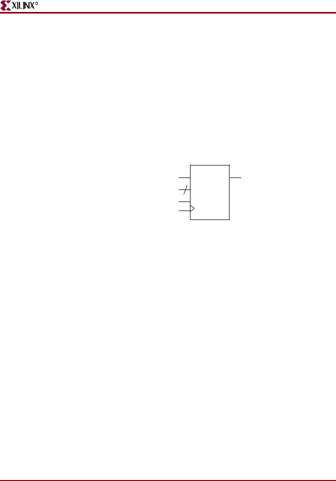
DYNAMIC
DATA 4 SRL Q
A
CE
C
X10542
Figure 2-30: 16-Bit Dynamic Shift Register With Positive-Edge Clock, Serial In and Serial
Out
Table 2-32, “16-Bit Dynamic Shift Register With Positive-Edge Clock, Serial In and Serial Out Pin Descriptions,” shows pin descriptions for a dynamic register. The register can:
•Be either serial or parallel
•Be left or right
•Have a synchronous or asynchronous reset
•Have a depth up to 16 bits.
Table 2-32: 16-Bit Dynamic Shift Register With Positive-Edge Clock, Serial In and Serial Out Pin Descriptions
IO Pins |
Description |
|
|
C |
Positive-Edge Clock |
|
|
SI |
Serial In |
|
|
AClr |
Asynchronous Reset |
|
|
SClr |
Synchronous Reset |
|
|
SLoad |
Synchronous Parallel Load |
|
|
Data |
Parallel Data Input Port |
|
|
ClkEn |
Clock Enable |
|
|
XST User Guide |
www.xilinx.com |
85 |
10.1

Chapter 2: XST HDL Coding Techniques
R
Table 2-32: 16-Bit Dynamic Shift Register With Positive-Edge Clock, Serial In and Serial Out Pin Descriptions (Cont’d)
IO Pins |
Description |
|
|
LeftRight |
Direction selection |
|
|
SerialInRight |
Serial Input Right for Bidirectional Shift Register |
|
|
PSO |
Serial or Parallel Output |
|
|
16-Bit Dynamic Shift Register With Positive-Edge Clock, Serial In and Serial Out VHDL Coding Example
--
-- 16-bit dynamic shift register.
--
library IEEE;
use IEEE.std_logic_1164.all; use IEEE.std_logic_unsigned.all;
entity dynamic_shift_registers_1 is port(CLK : in std_logic;
DATA : in std_logic; CE : in std_logic;
A : in std_logic_vector(3 downto 0); Q : out std_logic);
end dynamic_shift_registers_1;
architecture rtl of dynamic_shift_registers_1 is constant DEPTH_WIDTH : integer := 16;
type SRL_ARRAY is array (0 to DEPTH_WIDTH-1) of std_logic;
--The type SRL_ARRAY can be array
--(0 to DEPTH_WIDTH-1) of
--std_logic_vector(BUS_WIDTH downto 0)
--or array (DEPTH_WIDTH-1 downto 0) of
--std_logic_vector(BUS_WIDTH downto 0)
--(the subtype is forward (see below)) signal SRL_SIG : SRL_ARRAY;
begin
PROC_SRL16 : process (CLK) begin
if (CLK'event and CLK = '1') then if (CE = '1') then
SRL_SIG <= DATA & SRL_SIG(0 to DEPTH_WIDTH-2); end if;
end if; end process;
Q <= SRL_SIG(conv_integer(A));
end rtl;
86 |
www.xilinx.com |
XST User Guide |
|
|
10.1 |