

R
Arithmetic Operators HDL Coding Techniques
Arithmetic Operators HDL Coding Techniques
This section discusses Arithmetic Operators HDL Coding Techniques, and includes:
•“About Arithmetic Operators”
•“Arithmetic Operators Log File”
•“Arithmetic Operators Related Constraints”
•“Arithmetic Operators Coding Examples”
About Arithmetic Operators
XST supports the following arithmetic operators:
•Adders with:
♦Carry In
♦Carry Out
♦Carry In/Out
•Subtractors
•Adders/Subtractors
•Comparators (=, /=,<, <=, >, >=)
•Multipliers
•Dividers
Adders, subtractors, comparators and multipliers are supported for signed and unsigned operators.
For more information on signed and unsigned operators support in VHDL, see “Registers HDL Coding Techniques.”
Moreover, XST performs resource sharing for adders, subtractors, adders/subtractors and multipliers.
Arithmetic Operators Log File
The XST log file reports the type and size of recognized adder, subtractor and adder/subtractor during the Macro Recognition step.
...
Synthesizing Unit <adder>.
Related source file is arithmetic_operations_1.vhd. Found 8-bit adder for signal <sum>.
Summary:
inferred 1 Adder/Subtracter(s).
Unit <adder> synthesized. |
|
============================= |
|
HDL Synthesis Report |
|
Macro Statistics |
|
# Adders/Subtractors |
: 1 |
8-bit adder |
: 1 |
============================== |
|
XST User Guide |
www.xilinx.com |
111 |
10.1

Chapter 2: XST HDL Coding Techniques
R
Arithmetic Operators Related Constraints
•“Use DSP48 (USE_DSP48)”
•“DSP Utilization Ratio (DSP_UTILIZATION_RATIO)”
•“Keep (KEEP)”
Arithmetic Operators Coding Examples
The coding examples in this section are accurate as of the date of publication. Download updates from ftp://ftp.xilinx.com/pub/documentation/misc/examples_v9.zip. For examples of Arithmetic Operators, see the examples contained in the following sections:
•“Adders, Subtractors, and Adders/Subtractors HDL Coding Techniques”
•“Comparators HDL Coding Techniques”
•“Multipliers HDL Coding Techniques”
•“Sequential Complex Multipliers HDL Coding Techniques”
•“Pipelined Multipliers HDL Coding Techniques”
•“Multiply Adder/Subtractors HDL Coding Techniques”
•“Multiply Accumulate HDL Coding Techniques”
•“Dividers HDL Coding Techniques”
•“Resource Sharing HDL Coding Techniques”
Adders, Subtractors, and Adders/Subtractors HDL Coding
Techniques
This section discusses Adders, Subtractors, and Adders/Subtractors HDL Coding
Techniques, and includes:
•“About Adders, Subtractors, and Adders/Subtractors”
•“Adders, Subtractors, and Adders/Subtractors Log File”
•“Adders, Subtractors, and Adders/Subtractors Related Constraints”
•“Adders, Subtractors, and Adders/Subtractors Coding Examples”
About Adders, Subtractors, and Adders/Subtractors
The Virtex-4, Virtex-5, and Spartan-3A D families allow adders/subtractors to be implemented on DSP48 resources. XST supports the one level of output registers into DSP48 blocks. If the Carry In or Add/Sub operation selectors are registered, XST pushes these registers into the DSP48 as well.
XST can implement an adder/subtractor in a DSP48 block if its implementation requires only a single DSP48 resource. If an adder/subtractor macro does not fit in a single DSP48, XST implements the entire macro using slice logic.
Macro implementation on DSP48 blocks is controlled by “DSP Utilization Ratio (DSP_UTILIZATION_RATIO)” with a default value of auto. In auto mode, if an adder/subtractor is a part of a more complex macro such as a filter, XST automatically places it on the DSP block. Otherwise, XST implements adders/subtractors using LUTs. Set the value of “Use DSP48 (USE_DSP48)” to yes to force XST to push these macros into a DSP48. When placing an Adder/Subtractor on a DSP block, XST checks to see if it is
112 |
www.xilinx.com |
XST User Guide |
|
|
10.1 |

R
Adders, Subtractors, and Adders/Subtractors HDL Coding Techniques
connected to other DSP chains. If so, XST tries to take advantage of fast DSP connections, and connects this adder/subtractor to the DSP chain using these fast connections.
When implementing adders/subtractors on DSP48 blocks, XST performs automatic DSP48 resource control.
To deliver the best performance, XST by default tries to infer and implement the maximum macro configuration, including as many registers in the DSP48 as possible. Use the “Keep (KEEP)” constraint to shape a macro in a specific way. For example, to exclude the first register stage from the DSP48, place “Keep (KEEP)” constraints on the outputs of these registers.
Adders, Subtractors, and Adders/Subtractors Log File
Synthesizing Unit <v_adders_4>.
Related source file is "v_adders_4.v".
Found 8-bit adder carry in/out for signal <$addsub0000>. Summary:
inferred 1 Adder/Subtractor(s). Unit <v_adders_4> synthesized.
======================================================================
===
HDL Synthesis Report
Macro Statistics |
|
|
# Adders/Subtractors |
: |
1 |
8-bit adder carry in/out |
: |
1 |
======================================================================
===
Adders, Subtractors, and Adders/Subtractors Related Constraints
•“Use DSP48 (USE_DSP48)”
•“DSP Utilization Ratio (DSP_UTILIZATION_RATIO)”
•“Keep (KEEP)”
Adders, Subtractors, and Adders/Subtractors Coding Examples
The coding examples in this section are accurate as of the date of publication. Download updates from ftp://ftp.xilinx.com/pub/documentation/misc/examples_v9.zip.
•“Unsigned 8-Bit Adder”
•“Unsigned 8-Bit Adder With Carry In”
•“Unsigned 8-Bit Adder With Carry Out”
•“Unsigned 8-Bit Adder With Carry In and Carry Out”
•“Signed 8-Bit Adder”
•“Unsigned 8-Bit Subtractor”
•“Unsigned 8-Bit Subtractor With Borrow In”
•“Unsigned 8-Bit Adder/Subtractor”
XST User Guide |
www.xilinx.com |
113 |
10.1
Chapter 2: XST HDL Coding Techniques
R
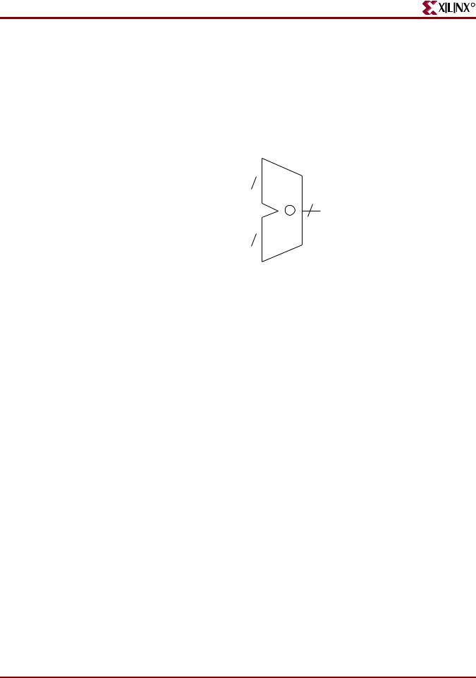
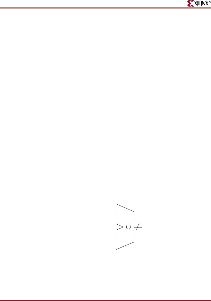
Unsigned 8-Bit Adder
This section discusses Unsigned 8-Bit Adder, and includes:
•“Unsigned 8-Bit Adder Diagram”
•“Unsigned 8-Bit Adder Pin Descriptions”
•“Unsigned 8-Bit Adder VHDL Coding Example”
•“Unsigned 8-Bit Adder Verilog Coding Example”
8
|
|
A |
|
|
|
|
|
|
|
||
|
8 |
|
|||
|
+ |
SUM |
|||
|
8 |
|
|
||
|
|
B |
|
|
X10549 |
|
|
|
|||
|
|
|
|
|
|
|
Figure 2-37: Unsigned 8-Bit Adder Diagram |
||||
Table 2-45: Unsigned 8-Bit Adder Pin Descriptions |
|
||||
|
|
|
|
|
|
IO Pins |
|
Description |
|
||
|
|
|
|
|
|
A, B |
|
Add Operands |
|
||
|
|
|
|
|
|
SUM |
|
Add Result |
|
||
|
|
|
|
|
|
Unsigned 8-Bit Adder VHDL Coding Example
--
-- Unsigned 8-bit Adder
--
library ieee;
use ieee.std_logic_1164.all; use ieee.std_logic_unsigned.all;
entity adders_1 is
port(A,B : in std_logic_vector(7 downto 0); SUM : out std_logic_vector(7 downto 0));
end adders_1;
architecture archi of adders_1 is begin
SUM <= A + B;
end archi;
114 |
www.xilinx.com |
XST User Guide |
|
|
10.1 |
R
Adders, Subtractors, and Adders/Subtractors HDL Coding Techniques
Unsigned 8-Bit Adder Verilog Coding Example
//
// Unsigned 8-bit Adder
//
module v_adders_1(A, B, SUM); input [7:0] A;
input [7:0] B; output [7:0] SUM;
assign SUM = A + B;
endmodule
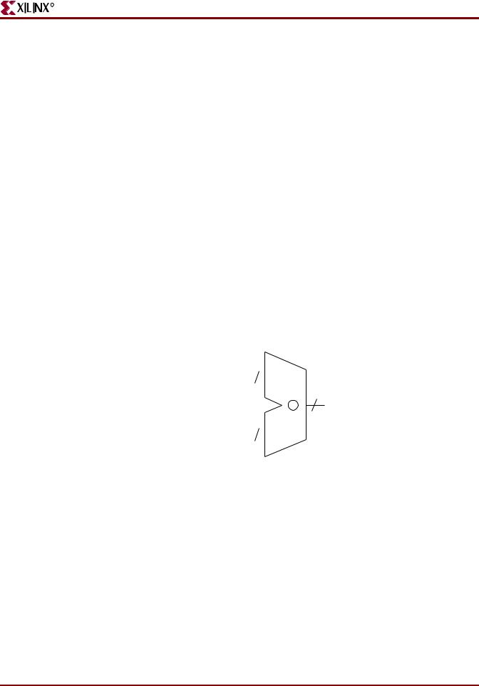
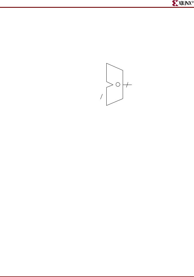
Unsigned 8-Bit Adder With Carry In
This section discusses Unsigned 8-Bit Adder With Carry In, and includes:
•“Unsigned 8-Bit Adder With Carry In Diagram”
•“Unsigned 8-Bit Adder With Carry In Pin Descriptions”
•“Unsigned 8-Bit Adder With Carry In VHDL Coding Example”
•“Unsigned 8-Bit Adder With Carry In Verilog Coding Example”
|
|
CI |
|
|
|
||
|
|
|
|
|
|||
|
8 |
|
|
|
|||
|
|
|
|
||||
|
|
A |
|
|
|
8 |
|
|
|
|
|||||
|
+ |
||||||
|
SUM |
||||||
|
8 |
|
|
|
|||
|
|
B |
|
|
|
X10550 |
|
|
|
|
|||||
|
|
|
|
|
|
|
|
|
Figure 2-38: Unsigned 8-Bit Adder With Carry In Diagram |
||||||
Table 2-46: Unsigned 8-Bit Adder With Carry In Pin Descriptions |
|||||||
|
|
|
|
|
|
|
|
IO Pins |
|
Description |
|
||||
|
|
|
|
|
|
|
|
A, B |
|
Add Operands |
|
||||
|
|
|
|
|
|
|
|
CI |
|
Carry In |
|
||||
|
|
|
|
|
|
|
|
SUM |
|
Add Result |
|
||||
|
|
|
|
|
|
|
|
Unsigned 8-Bit Adder With Carry In VHDL Coding Example
--
-- Unsigned 8-bit Adder with Carry In
--
library ieee;
XST User Guide |
www.xilinx.com |
115 |
10.1

Chapter 2: XST HDL Coding Techniques
R
use ieee.std_logic_1164.all; use ieee.std_logic_unsigned.all;
entity adders_2 is
port(A,B : in std_logic_vector(7 downto 0); CI : in std_logic;
SUM : out std_logic_vector(7 downto 0)); end adders_2;
architecture archi of adders_2 is begin
SUM <= A + B + CI;
end archi;
Unsigned 8-Bit Adder With Carry In Verilog Coding Example
//
// Unsigned 8-bit Adder with Carry In
//
module v_adders_2(A, B, CI, SUM); input [7:0] A;
input [7:0] B; input CI;
output [7:0] SUM;
assign SUM = A + B + CI;
endmodule
Unsigned 8-Bit Adder With Carry Out
This section discusses Unsigned 8-Bit Adder With Carry Out, and includes:
•“Unsigned 8-Bit Adder With Carry Out Diagram”
•“Unsigned 8-Bit Adder With Carry Out Pin Descriptions”
•“Unsigned 8-Bit Adder With Carry Out VHDL Coding Example”
•“Unsigned 8-Bit Adder With Carry Out Verilog Coding Example”
Before writing a + (plus) operation with carry out in VHDL, read the arithmetic package you plan to use. For example, std_logic_unsigned does not allow you to write + (plus) in the following form to obtain Carry Out:
Res(9-bit) = A(8-bit) + B(8-bit)
The reason is that the size of the result for + (plus) in this package is equal to the size of the longest argument (8 bits).
One solution for the example is to adjust the size of operands A and B to 9 bits using concatenation.
Res <= ("0" & A) + ("0" & B);
116 |
www.xilinx.com |
XST User Guide |
|
|
10.1 |
R
Adders, Subtractors, and Adders/Subtractors HDL Coding Techniques
In this case, XST recognizes that this 9-bit adder can be implemented as an 8-bit adder with carry out.
Another solution is:
•Convert A and B to integers
•Convert the result back to the std_logic vector
•Specify the size of the vector equal to 9
8
|
|
A |
|
|
|
8 |
|
|
|
|
|
|
|
||||
|
|
|
|
|
|
|
|
|
|
+ |
|
|
SUM |
||||
|
|
|
||||||
|
8 |
|
|
|
|
|
||
|
|
B |
|
|
|
|
|
CO |
|
|
|
|
|
||||
|
|
|
|
|
|
|
|
|
|
|
|
|
|
|
|
|
|
|
|
|
|
|
|
|
||
|
|
|
|
|
|
|
|
X10551 |
|
Figure 2-39: Unsigned 8-Bit Adder With Carry Out Diagram |
|||||||
Table 2-47: Unsigned 8-Bit Adder With Carry Out Pin Descriptions |
||||||||
|
|
|
|
|
|
|
|
|
IO Pins |
|
Description |
|
|
|
|||
|
|
|
|
|
|
|
|
|
A, B |
|
Add Operands |
|
|
|
|||
|
|
|
|
|
|
|
|
|
SUM |
|
Add Result |
|
|
|
|||
|
|
|
|
|
|
|
|
|
CO |
|
Carry Out |
|
|
|
|||
|
|
|
|
|
|
|
|
|
Unsigned 8-Bit Adder With Carry Out VHDL Coding Example
--
-- Unsigned 8-bit Adder with Carry Out
--
library ieee;
use ieee.std_logic_1164.all; use ieee.std_logic_arith.all; use ieee.std_logic_unsigned.all;
entity adders_3 is
port(A,B : in std_logic_vector(7 downto 0); SUM : out std_logic_vector(7 downto 0); CO : out std_logic);
end adders_3;
architecture archi of adders_3 is
signal tmp: std_logic_vector(8 downto 0); begin
tmp <= conv_std_logic_vector((conv_integer(A) + conv_integer(B)),9);
SUM <= tmp(7 downto 0);
XST User Guide |
www.xilinx.com |
117 |
10.1

Chapter 2: XST HDL Coding Techniques
R
CO <= tmp(8);
end archi;
The preceding example uses two arithmetic packages:
•std_logic_arith
Contains the integer to std_logic conversion function (conv_std_logic_vector)
•std_logic_unsigned
Contains the unsigned + (plus) operation
Unsigned 8-Bit Adder With Carry Out Verilog Coding Example
//
// Unsigned 8-bit Adder with Carry Out
//
module v_adders_3(A, B, SUM, CO); input [7:0] A;
input [7:0] B; output [7:0] SUM; output CO;
wire [8:0] tmp;
assign tmp = A + B; assign SUM = tmp [7:0]; assign CO = tmp [8];
endmodule
118 |
www.xilinx.com |
XST User Guide |
|
|
10.1 |
R
Adders, Subtractors, and Adders/Subtractors HDL Coding Techniques
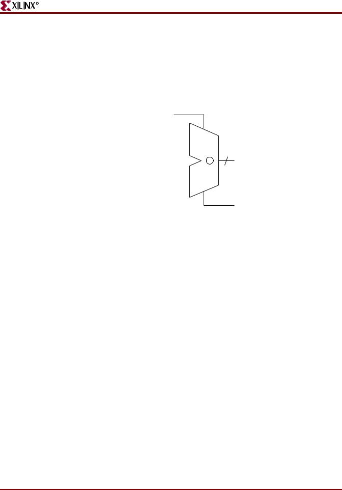
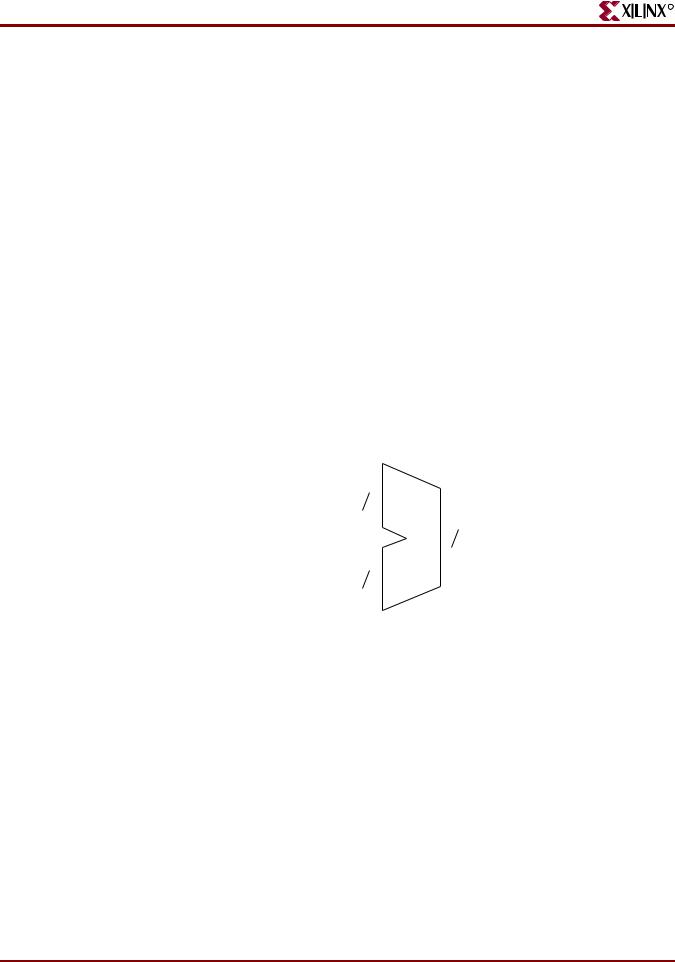
Unsigned 8-Bit Adder With Carry In and Carry Out
This section discusses Unsigned 8-Bit Adder With Carry In and Carry Out, and includes:
•“Unsigned 8-Bit Adder With Carry In and Carry Out Diagram”
•“Unsigned 8-Bit Adder With Carry In and Carry Out Pin Descriptions”
•“Unsigned 8-Bit Adder With Carry In and Carry Out VHDL Coding Example”
•“Unsigned 8-Bit Adder With Carry In and Carry Out Verilog Coding Example”
CI
8 A 
8
+ SUM
8 B 
CO
X10552
Figure 2-40: Unsigned 8-Bit Adder With Carry In and Carry Out Diagram
Table 2-48: Unsigned 8-Bit Adder With Carry In and Carry Out Pin Descriptions
IO Pins |
Description |
|
|
A, B |
Add Operands |
|
|
CI |
Carry In |
|
|
SUM |
Add Result |
|
|
CO |
Carry Out |
|
|
Unsigned 8-Bit Adder With Carry In and Carry Out VHDL Coding Example
--
-- Unsigned 8-bit Adder with Carry In and Carry Out
--
library ieee;
use ieee.std_logic_1164.all; use ieee.std_logic_arith.all; use ieee.std_logic_unsigned.all;
entity adders_4 is
port(A,B : in std_logic_vector(7 downto 0); CI : in std_logic;
SUM : out std_logic_vector(7 downto 0); CO : out std_logic);
end adders_4;
architecture archi of adders_4 is
signal tmp: std_logic_vector(8 downto 0);
XST User Guide |
www.xilinx.com |
119 |
10.1
Chapter 2: XST HDL Coding Techniques
R
begin
tmp <= conv_std_logic_vector((conv_integer(A) + conv_integer(B) + conv_integer(CI)),9);
SUM <= tmp(7 downto 0); CO <= tmp(8);
end archi;
Unsigned 8-Bit Adder With Carry In and Carry Out Verilog Coding Example
//
// Unsigned 8-bit Adder with Carry In and Carry Out
//
module v_adders_4(A, B, CI, SUM, CO); input CI;
input [7:0] A; input [7:0] B; output [7:0] SUM; output CO;
wire [8:0] tmp;
assign tmp = A + B + CI; assign SUM = tmp [7:0]; assign CO = tmp [8];
endmodule
Signed 8-Bit Adder
This section discusses Signed 8-Bit Adder, and includes:
•“Signed 8-Bit Adder Diagram”
•“Signed 8-Bit Adder Pin Descriptions”
•“Signed 8-Bit Adder VHDL Coding Example”
•“Signed 8-Bit Adder Verilog Coding Example”
8 A 
8
+ SUM
8 B 
X10549
Figure 2-41: Signed 8-Bit Adder Diagram
120 |
www.xilinx.com |
XST User Guide |
|
|
10.1 |
R
Adders, Subtractors, and Adders/Subtractors HDL Coding Techniques
.
Table 2-49: Signed 8-Bit Adder Pin Descriptions
IO Pins |
Description |
|
|
A, B |
Add Operands |
|
|
SUM |
Add Result |
|
|
Signed 8-Bit Adder VHDL Coding Example
--
-- Signed 8-bit Adder
--
library ieee;
use ieee.std_logic_1164.all; use ieee.std_logic_signed.all;
entity adders_5 is
port(A,B : in std_logic_vector(7 downto 0); SUM : out std_logic_vector(7 downto 0));
end adders_5;
architecture archi of adders_5 is begin
SUM <= A + B;
end archi;
Signed 8-Bit Adder Verilog Coding Example
//
// Signed 8-bit Adder
//
module v_adders_5 (A,B,SUM); input signed [7:0] A; input signed [7:0] B; output signed [7:0] SUM; wire signed [7:0] SUM;
assign SUM = A + B;
endmodule
XST User Guide |
www.xilinx.com |
121 |
10.1
Chapter 2: XST HDL Coding Techniques
R
Unsigned 8-Bit Subtractor
This section discusses Unsigned 8-Bit Subtractor, and includes:
•“Unsigned 8-Bit Subtractor Diagram”
•“Unsigned 8-Bit Subtractor Pin Descriptions”
•“Unsigned 8-Bit Subtractor VHDL Coding Example”
•“Unsigned 8-Bit Subtractor Verilog Coding Example”
8 A 
|
8 |
|||||
|
8 |
|
|
SUM |
||
|
|
|
||||
|
|
|
|
|||
|
|
B |
|
|
|
X10553 |
|
|
|
||||
|
|
|
|
|
|
|
|
Figure 2-42: Unsigned 8-Bit Subtractor Diagram |
|||||
Table 2-50: Unsigned 8-Bit Subtractor Pin Descriptions |
||||||
|
|
|
|
|
|
|
IO Pins |
|
Description |
||||
|
|
|
|
|
|
|
A, B |
|
Sub Operands |
||||
|
|
|
|
|
|
|
RES |
|
Sub Result |
||||
|
|
|
|
|
|
|
Unsigned 8-Bit Subtractor VHDL Coding Example
--
-- Unsigned 8-bit Subtractor
--
library ieee;
use ieee.std_logic_1164.all; use ieee.std_logic_unsigned.all;
entity adders_6 is
port(A,B : in std_logic_vector(7 downto 0); RES : out std_logic_vector(7 downto 0));
end adders_6;
architecture archi of adders_6 is begin
RES <= A - B;
end archi;
122 |
www.xilinx.com |
XST User Guide |
|
|
10.1 |

R
Adders, Subtractors, and Adders/Subtractors HDL Coding Techniques
Unsigned 8-Bit Subtractor Verilog Coding Example
//
// Unsigned 8-bit Subtractor
//
module v_adders_6(A, B, RES); input [7:0] A;
input [7:0] B; output [7:0] RES;
assign RES = A - B;
endmodule
Unsigned 8-Bit Subtractor With Borrow In
This section discusses Unsigned 8-Bit Subtractor With Borrow In, and includes:
•“Unsigned 8-Bit Subtractor With Borrow In Pin Descriptions”
•“Unsigned 8-Bit Subtractor With Borrow In VHDL Coding Example”
•“Unsigned 8-Bit Subtractor With Borrow In Verilog Coding Example”
Table 2-51: Unsigned 8-Bit Subtractor With Borrow In Pin Descriptions
IO Pins |
Description |
|
|
A, B |
Sub Operands |
|
|
BI |
Borrow In |
|
|
RES |
Sub Result |
|
|
Unsigned 8-Bit Subtractor With Borrow In VHDL Coding Example
--
-- Unsigned 8-bit Subtractor with Borrow In
--
library IEEE;
use IEEE.STD_LOGIC_1164.ALL; use IEEE.STD_LOGIC_UNSIGNED.ALL;
entity adders_8 is
port(A,B : in std_logic_vector(7 downto 0); BI : in std_logic;
RES : out std_logic_vector(7 downto 0)); end adders_8;
architecture archi of adders_8 is
begin
RES <= A - B - BI;
end archi;
XST User Guide |
www.xilinx.com |
123 |
10.1
Chapter 2: XST HDL Coding Techniques
Unsigned 8-Bit Subtractor With Borrow In Verilog Coding Example
//
// Unsigned 8-bit Subtractor with Borrow In
//
module v_adders_8(A, B, BI, RES);
input |
[7:0] A; |
|
input |
[7:0] B; |
|
input |
|
BI; |
output |
[7:0] |
RES; |
assign |
RES = |
A - B - BI; |
endmodule
R
Unsigned 8-Bit Adder/Subtractor
This section discusses Unsigned 8-Bit Adder/Subtractor, and includes:
•“Unsigned 8-Bit Adder/Subtractor Diagram”
•“Unsigned 8-Bit Adder/Subtractor Pin Descriptions”
•“Unsigned 8-Bit Adder/Subtractor VHDL Coding Example”
•“Unsigned 8-Bit Adder/Subtractor Verilog Coding Example”
8
|
|
A |
|
|
|
|
|
|
|
8 |
|
|
|
|
|
|
|||||||
|
+/ |
|
|
|
|
||||||
|
|
|
|
|
SUM |
||||||
|
|
|
|
|
|||||||
|
8 |
|
|
|
|
|
|
|
|||
|
|
B |
|
|
|
|
|
|
|
|
|
|
|
|
|
|
|
||||||
|
OPER |
|
|
X10554 |
|||||||
|
|
|
|
||||||||
|
|
|
|
||||||||
|
Figure 2-43: Unsigned 8-Bit Adder/Subtractor Diagram |
||||||||||
Table 2-52: Unsigned 8-Bit Adder/Subtractor Pin Descriptions |
|||||||||||
|
|
|
|
|
|
|
|
|
|
|
|
IO Pins |
|
Description |
|
|
|||||||
|
|
|
|
|
|
|
|
|
|
|
|
A, B |
|
Add/Sub Operands |
|
|
|||||||
|
|
|
|
|
|
|
|
|
|
|
|
OPER |
|
Add/Sub Select |
|
|
|||||||
|
|
|
|
|
|
|
|
|
|
|
|
SUM |
|
Add/Sub Result |
|
|
|||||||
|
|
|
|
|
|
|
|
|
|
|
|
Unsigned 8-Bit Adder/Subtractor VHDL Coding Example
--
-- Unsigned 8-bit Adder/Subtractor
--
library ieee;
use ieee.std_logic_1164.all;
124 |
www.xilinx.com |
XST User Guide |
|
|
10.1 |