

- •About the Authors
- •Dedication
- •Authors’ Acknowledgments
- •Table of Contents
- •Introduction
- •What’s Not (And What Is) in This Book
- •Mac attack!
- •Who Do We Think You Are?
- •How This Book Is Organized
- •Part I: AutoCAD 101
- •Part II: Let There Be Lines
- •Part III: If Drawings Could Talk
- •Part IV: Advancing with AutoCAD
- •Part V: On a 3D Spree
- •Part VI: The Part of Tens
- •But wait . . . there’s more!
- •Icons Used in This Book
- •A Few Conventions — Just in Case
- •Commanding from the keyboard
- •Tying things up with the Ribbon
- •Where to Go from Here
- •Why AutoCAD?
- •The Importance of Being DWG
- •Seeing the LT
- •Checking System Requirements
- •Suddenly, It’s 2013!
- •AutoCAD Does Windows (And Office)
- •And They’re Off: AutoCAD’s Opening Screens
- •Running with Ribbons
- •Getting with the Program
- •Looking for Mr. Status Bar
- •Let your fingers do the talking: The command window
- •The key(board) to AutoCAD success
- •Keeping tabs on palettes
- •Down the main stretch: The drawing area
- •Fun with F1
- •A Simple Setup
- •Drawing a (Base) Plate
- •Drawing rectangles on the right layers
- •Circling your plate
- •Nuts to you
- •Getting a Closer Look with Zoom and Pan
- •Modifying to Make It Merrier
- •Hip-hip-array!
- •Stretching out
- •Crossing your hatches
- •Following the Plot
- •A Setup Roadmap
- •Choosing your units
- •Weighing up your scales
- •Thinking annotatively
- •Thinking about paper
- •Defending your border
- •A Template for Success
- •Making the Most of Model Space
- •Setting your units
- •Making the drawing area snap-py (and grid-dy)
- •Setting linetype and dimension scales
- •Entering drawing properties
- •Making Templates Your Own
- •Setting Up a Layout in Paper Space
- •Will that be tabs or buttons?
- •View layouts Quick(View)ly
- •Creating a layout
- •Copying and changing layouts
- •Lost in paper space
- •Spaced out
- •A view(port) for drawing in
- •About Paper Space Layouts and Plotting
- •Managing Your Properties
- •Layer one on me!
- •Accumulating properties
- •Creating new layers
- •Manipulating layers
- •Using Named Objects
- •Using AutoCAD DesignCenter
- •Copying layers between drawings
- •Controlling Your Precision
- •Keyboard capers: Coordinate input
- •Understanding AutoCAD’s coordinate systems
- •Grab an object and make it snappy
- •Other Practical Precision Procedures
- •Introducing the AutoCAD Drawing Commands
- •The Straight and Narrow: Lines, Polylines, and Polygons
- •Toeing the line
- •Connecting the lines with polyline
- •Squaring off with rectangles
- •Choosing your sides with polygon
- •(Throwing) Curves
- •Going full circle
- •Arc-y-ology
- •Solar ellipses
- •Splines: The sketchy, sinuous curves
- •Donuts: The circles with a difference
- •Revision clouds on the horizon
- •Scoring Points
- •Commanding and Selecting
- •Command-first editing
- •Selection-first editing
- •Direct object manipulation
- •Choosing an editing style
- •Grab It
- •One-by-one selection
- •Selection boxes left and right
- •Perfecting Selecting
- •AutoCAD Groupies
- •Object Selection: Now You See It . . .
- •Get a Grip
- •About grips
- •A gripping example
- •Move it!
- •Copy, or a kinder, gentler Move
- •A warm-up stretch
- •Your AutoCAD Toolkit
- •The Big Three: Move, Copy, and Stretch
- •Base points and displacements
- •Move
- •Copy
- •Copy between drawings
- •Stretch
- •More Manipulations
- •Mirror
- •Rotate
- •Scale
- •Array
- •Offset
- •Slicing, Dicing, and Splicing
- •Trim and Extend
- •Break
- •Fillet and Chamfer and Blend
- •Join
- •When Editing Goes Bad
- •Zoom and Pan with Glass and Hand
- •The wheel deal
- •Navigating your drawing
- •Controlling your cube
- •Time to zoom
- •A View by Any Other Name . . .
- •Looking Around in Layout Land
- •Degenerating and Regenerating
- •Getting Ready to Write
- •Simply stylish text
- •Taking your text to new heights
- •One line or two?
- •Your text will be justified
- •Using the Same Old Line
- •Turning On Your Annotative Objects
- •Saying More in Multiline Text
- •Making it with Mtext
- •It slices; it dices . . .
- •Doing a number on your Mtext lists
- •Line up in columns — now!
- •Modifying Mtext
- •Gather Round the Tables
- •Tables have style, too
- •Creating and editing tables
- •Take Me to Your Leader
- •Electing a leader
- •Multi options for multileaders
- •How Do You Measure Up?
- •A Field Guide to Dimensions
- •The lazy drafter jumps over to the quick dimension commands
- •Dimension associativity
- •Where, oh where, do my dimensions go?
- •The Latest Styles in Dimensioning
- •Creating and managing dimension styles
- •Let’s get stylish!
- •Adjusting style settings
- •Size Matters
- •Details at other scales
- •Editing Dimensions
- •Editing dimension geometry
- •Editing dimension text
- •Controlling and editing dimension associativity
- •Batten Down the Hatches!
- •Don’t Count Your Hatches. . .
- •Size Matters!
- •We can do this the hard way. . .
- •. . . or we can do this the easy way
- •Annotative versus non-annotative
- •Pushing the Boundary (Of) Hatch
- •Your hatching has no style!
- •Hatch from scratch
- •Editing Hatch Objects
- •You Say Printing, We Say Plotting
- •The Plot Quickens
- •Plotting success in 16 steps
- •Get with the system
- •Configure it out
- •Preview one, two
- •Instead of fit, scale it
- •Plotting the Layout of the Land
- •Plotting Lineweights and Colors
- •Plotting with style
- •Plotting through thick and thin
- •Plotting in color
- •It’s a (Page) Setup!
- •Continuing the Plot Dialog
- •The Plot Sickens
- •Rocking with Blocks
- •Creating Block Definitions
- •Inserting Blocks
- •Attributes: Fill-in-the-Blank Blocks
- •Creating attribute definitions
- •Defining blocks that contain attribute definitions
- •Inserting blocks that contain attribute definitions
- •Edit attribute values
- •Extracting data
- •Exploding Blocks
- •Purging Unused Block Definitions
- •Arraying Associatively
- •Comparing the old and new ARRAY commands
- •Hip, hip, array!
- •Associatively editing
- •Going External
- •Becoming attached to your xrefs
- •Layer-palooza
- •Creating and editing an external reference file
- •Forging an xref path
- •Managing xrefs
- •Blocks, Xrefs, and Drawing Organization
- •Mastering the Raster
- •Attaching a raster image
- •Maintaining your image
- •Theme and Variations: Dynamic Blocks
- •Lights! Parameters!! Actions!!!
- •Manipulating dynamic blocks
- •Maintaining Design Intent
- •Defining terms
- •Forget about drawing with precision!
- •Constrain yourself
- •Understanding Geometric Constraints
- •Applying a little more constraint
- •AutoConstrain yourself!
- •Understanding Dimensional Constraints
- •Practice a little constraint
- •Making your drawing even smarter
- •Using the Parameters Manager
- •Dimensions or constraints — have it both ways!
- •The Internet and AutoCAD: An Overview
- •You send me
- •Send it with eTransmit
- •Rapid eTransmit
- •Bad reception?
- •Help from the Reference Manager
- •Design Web Format — Not Just for the Web
- •All about DWF and DWFx
- •Autodesk Design Review 2013
- •The Drawing Protection Racket
- •Autodesk Weather Forecast: Increasing Cloud
- •Working Solidly in the Cloud
- •Free AutoCAD!
- •Going once, going twice, going 123D
- •Your head planted firmly in the cloud
- •The pros
- •The cons
- •Cloudy with a shower of DWGs
- •AutoCAD 2013 cloud connectivity
- •Tomorrow’s Forecast
- •Understanding 3D Digital Models
- •Tools of the Trade
- •Warp speed ahead
- •Entering the third dimension
- •Untying the Ribbon and opening some palettes
- •Modeling from Above
- •Using 3D coordinate input
- •Using point filters
- •Object snaps and object snap tracking
- •Changing Planes
- •Displaying the UCS icon
- •Adjusting the UCS
- •Navigating the 3D Waters
- •Orbit à go-go
- •Taking a spin around the cube
- •Grabbing the SteeringWheels
- •Visualizing 3D Objects
- •Getting Your 3D Bearings
- •Creating a better 3D template
- •Seeing the world from new viewpoints
- •From Drawing to Modeling in 3D
- •Drawing basic 3D objects
- •Gaining a solid foundation
- •Drawing solid primitives
- •Adding the Third Dimension to 2D Objects
- •Creating 3D objects from 2D drawings
- •Modifying 3D Objects
- •Selecting subobjects
- •Working with gizmos
- •More 3D variants of 2D commands
- •Editing solids
- •Get the 2D Out of Here!
- •A different point of view
- •But wait! There’s more!
- •But wait! There’s less!
- •Do You See What I See?
- •Visualizing the Digital World
- •Adding Lighting
- •Default lighting
- •User-defined lights
- •Sunlight
- •Creating and Applying Materials
- •Defining a Background
- •Rendering a 3D Model
- •Autodesk Feedback Community
- •Autodesk Discussion Groups
- •Autodesk’s Own Bloggers
- •Autodesk University
- •The Autodesk Channel on YouTube
- •The World Wide (CAD) Web
- •Your Local ATC
- •Your Local User Group
- •AUGI
- •Books
- •Price
- •3D Abilities
- •Customization Options
- •Network Licensing
- •Express Tools
- •Parametrics
- •Standards Checking
- •Data Extraction
- •MLINE versus DLINE
- •Profiles
- •Reference Manager
- •And The Good News Is . . .
- •APERTURE
- •DIMASSOC
- •MENUBAR
- •MIRRTEXT
- •OSNAPZ
- •PICKBOX
- •REMEMBERFOLDERS
- •ROLLOVERTIPS
- •TOOLTIPS
- •VISRETAIN
- •And the Bonus Round
- •Index

Chapter 18: Everything from Arrays to Xrefs 399
separately. Simply select it and then edit it like the object that it is. When you’re finished, the path array updates to match the revised path.
And no matter how much tinkering you do, you can always revert to the original state by clicking Reset Array on the Options panel of the Array tab.
Going External
In AutoCAD, an xref (external reference) is a reference to another external drawing file — one outside the current drawing — that acts as though it’s part of your drawing. Technically, a reference is simply a pointer from one file to another. The xref is the actual pointer, but many people call the combination of the pointer and the external file the “xref.”
In both AutoCAD and AutoCAD LT, external drawing files are just one of several file types you can attach to your current drawing via the Select Reference File dialog box. You use this dialog box to attach externally referenced AutoCAD drawings (xrefs), raster image files, DWF and DWFx files, PDF files, and MicroStation DGN drawing files, among others.
Use the Attach button of the Insert tab Reference panel to open the Select Reference File dialog box. When you attach an external drawing to your current drawing, you become the host of the external file. No need to break out the cocktails and canapés, though, because it’s actually your current drawing that’s doing the hosting — and in AutoCAD, it’s called (what else?) the host drawing. You can think of the attached xrefs as guests, but most of the time they’re pretty well-behaved ones — and like the best of guests, they go away as soon as you want them to.
Xrefs have a big advantage over blocks: If a drawing is inserted as a block into another drawing, its geometry doesn’t change if the original drawing is changed in any way — it always looks the way it looks when it’s inserted. If that drawing is attached as an xref, however, AutoCAD will automatically update every host drawing to which it’s attached when the host drawing is
reopened. You can also manually reload the changed xref if you don’t want to close and reopen the host drawing.
When you open a drawing that contains xrefs, AutoCAD displays a little symbol (looks like papers with a binder clip) on the right end of the status bar. This symbol alerts you that some of the things you see in the drawing are actually parts of other, xref-ed drawings. If an xref changes while you have the host drawing open (because you or someone else opens and saves the referenced drawing), the status bar xref symbol displays an External Reference Files Have Changed balloon notification. Simply click the
www.it-ebooks.info

400 Part IV: Advancing with AutoCAD
Reload link in the balloon notification to show the updated xrefs. (If you want to change how AutoCAD checks for changes, look up XREFNOTIFY in the online help.)
Another advantage that xrefs have over blocks is that their contents aren’t stored in your drawing even once. The disk storage space taken up by the original drawing (the xref) isn’t duplicated, no matter how many host drawings reference it. This characteristic makes xrefs much more efficient than blocks for larger drawings that are reused several times.
Sure, you can always buy a larger hard drive, so the storage issue isn’t crucial. The key benefit of xrefs is that they enable you to organize your drawings so the changes you make to a single drawing file automatically ripple through all the host drawings into which it’s xref-ed. This benefit is even greater on larger projects involving multiple drafters, each of whose work may be incorporated in part or in whole in the work of others.
You can use xrefs to your advantage in almost any type of drawing. For example, several drafters might be working on the components for a large machine, while one master drawing brings them all together in the final assembly. Similarly, a set of separate architectural drawings could show electrical, plumbing, HVAV, and so on with everyone referencing the same floor plan. The host file would contain nothing but a title block and xrefs to the other files.
However, the automatic update feature of xrefs is a big advantage only if you’re organized about how you use xrefs. Suppose that an architect creates a plan drawing showing a building’s walls and other major features that are common to the architectural, structural, plumbing, and electrical plan drawings. The architect then tells the structural, plumbing, and electrical drafters to xref this background plan into their drawings so that everyone is working from a consistent and reusable set of common plan elements. If the architect decides to revise the wall locations and updates the xref-ed drawing, everyone will see the current wall configuration and be able to change their drawings. But if the architect absent-mindedly adds architecture-specific objects (toilets and furniture, for example) to the xref-ed drawing, or shifts all the objects with respect to 0,0, everyone else will have problems. If different people in your office share xrefs, create a protocol for who is allowed to modify which file when, and what communication needs to take place after a shared xref is modified.
Becoming attached to your xrefs
Attaching an external reference drawing is similar to inserting a block, and almost as easy. Just use the following steps:
www.it-ebooks.info
Chapter 18: Everything from Arrays to Xrefs 401
1. Set an appropriate layer current, as described in Chapter 6.
Insert xrefs on a separate layer from all other objects.
Note that if you freeze the layer on which an xref is inserted, the entire xref disappears. (This behavior can be a handy trick, a nasty surprise, or a fun trick.)
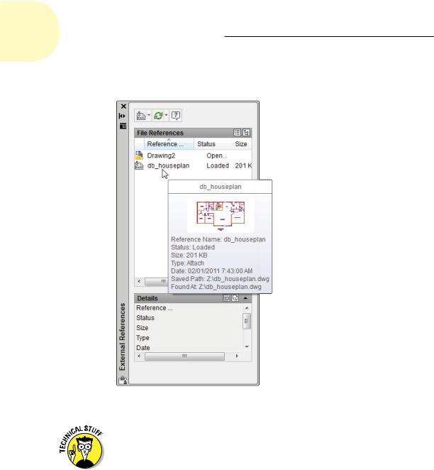
2.If the External References palette isn’t already open, click its icon (it looks like a sheaf of papers with a bulldog clip and a silhouetted user) on the Palettes panel of the View tab to open it.
Use the toolbar at the top of the palette to attach an external DWG file, a DWF underlay, a PDF underlay, a MicroStation DGN drawing file, a raster image file, or a point cloud. We cover attaching images and DWFs or PDFs later in this chapter. If you need to attach DGN files, visit the online help.
3.Click Attach DWG. Click the down arrow if the tooltip offers to attach something else — see Figure 18-4.
The Select Reference File dialog box appears.
4.Browse to find the file you want to attach, select it, and then click Open.
The Attach External Reference dialog box appears.
5.Specify the parameters for the xref in the dialog box.
Parameters include the insertion point, scaling factors, location based on geographic data, and rotation angle. (We describe geographic location briefly in Chapter 17.) You can set these parameters in the dialog box or specify them onscreen, just like you can do when inserting a block, as described in Chapter 17.
The Path Type drop-down list provides more flexibility in how the xref path is stored. See the “Forging an xref path” section, later in this chapter, for more information.
We recommend that you choose Relative Path instead of Full Path.
6.Click OK.
The externally referenced file appears in your drawing.
In drawings that contain many xrefs, locating the one you want can be difficult. When you select an object that’s part of an xref in the drawing area, the xref name is highlighted in the External References palette. Likewise, selecting an xref in the External References palette highlights the attached file geometry in the drawing editor.
www.it-ebooks.info
402 Part IV: Advancing with AutoCAD
|
|
List View |
|||
Attach DWG |
|
Tree View |
|||
|
|
|
|
|
|
|
|
|
|
|
|
|
|
|
|
|
|
Figure 18-4: Use the External References palette to attach an xref.
You can select either the Attachment or Overlay radio button to tell AutoCAD how to handle the xref. The choice matters only if you create a drawing that uses xrefs, and then your drawing is, in turn, used as an xref. Attachment is the default choice, and it dictates that the xref-ed file will always be included with your drawing when someone else uses your drawing as an xref. Overlay, the other choice, means that you see the xref-ed drawing, but someone who xrefs your drawing won’t see the overlaid file. By choosing Overlay, you can xref a map, for example, to your drawing of a house, but the map won’t show up when someone else xrefs your house drawing. (That person can xref the map, if needed.) We recommend that you use the default Attachment reference type unless you have a specific reason not to.
www.it-ebooks.info