

- •About the Authors
- •Dedication
- •Authors’ Acknowledgments
- •Table of Contents
- •Introduction
- •What’s Not (And What Is) in This Book
- •Mac attack!
- •Who Do We Think You Are?
- •How This Book Is Organized
- •Part I: AutoCAD 101
- •Part II: Let There Be Lines
- •Part III: If Drawings Could Talk
- •Part IV: Advancing with AutoCAD
- •Part V: On a 3D Spree
- •Part VI: The Part of Tens
- •But wait . . . there’s more!
- •Icons Used in This Book
- •A Few Conventions — Just in Case
- •Commanding from the keyboard
- •Tying things up with the Ribbon
- •Where to Go from Here
- •Why AutoCAD?
- •The Importance of Being DWG
- •Seeing the LT
- •Checking System Requirements
- •Suddenly, It’s 2013!
- •AutoCAD Does Windows (And Office)
- •And They’re Off: AutoCAD’s Opening Screens
- •Running with Ribbons
- •Getting with the Program
- •Looking for Mr. Status Bar
- •Let your fingers do the talking: The command window
- •The key(board) to AutoCAD success
- •Keeping tabs on palettes
- •Down the main stretch: The drawing area
- •Fun with F1
- •A Simple Setup
- •Drawing a (Base) Plate
- •Drawing rectangles on the right layers
- •Circling your plate
- •Nuts to you
- •Getting a Closer Look with Zoom and Pan
- •Modifying to Make It Merrier
- •Hip-hip-array!
- •Stretching out
- •Crossing your hatches
- •Following the Plot
- •A Setup Roadmap
- •Choosing your units
- •Weighing up your scales
- •Thinking annotatively
- •Thinking about paper
- •Defending your border
- •A Template for Success
- •Making the Most of Model Space
- •Setting your units
- •Making the drawing area snap-py (and grid-dy)
- •Setting linetype and dimension scales
- •Entering drawing properties
- •Making Templates Your Own
- •Setting Up a Layout in Paper Space
- •Will that be tabs or buttons?
- •View layouts Quick(View)ly
- •Creating a layout
- •Copying and changing layouts
- •Lost in paper space
- •Spaced out
- •A view(port) for drawing in
- •About Paper Space Layouts and Plotting
- •Managing Your Properties
- •Layer one on me!
- •Accumulating properties
- •Creating new layers
- •Manipulating layers
- •Using Named Objects
- •Using AutoCAD DesignCenter
- •Copying layers between drawings
- •Controlling Your Precision
- •Keyboard capers: Coordinate input
- •Understanding AutoCAD’s coordinate systems
- •Grab an object and make it snappy
- •Other Practical Precision Procedures
- •Introducing the AutoCAD Drawing Commands
- •The Straight and Narrow: Lines, Polylines, and Polygons
- •Toeing the line
- •Connecting the lines with polyline
- •Squaring off with rectangles
- •Choosing your sides with polygon
- •(Throwing) Curves
- •Going full circle
- •Arc-y-ology
- •Solar ellipses
- •Splines: The sketchy, sinuous curves
- •Donuts: The circles with a difference
- •Revision clouds on the horizon
- •Scoring Points
- •Commanding and Selecting
- •Command-first editing
- •Selection-first editing
- •Direct object manipulation
- •Choosing an editing style
- •Grab It
- •One-by-one selection
- •Selection boxes left and right
- •Perfecting Selecting
- •AutoCAD Groupies
- •Object Selection: Now You See It . . .
- •Get a Grip
- •About grips
- •A gripping example
- •Move it!
- •Copy, or a kinder, gentler Move
- •A warm-up stretch
- •Your AutoCAD Toolkit
- •The Big Three: Move, Copy, and Stretch
- •Base points and displacements
- •Move
- •Copy
- •Copy between drawings
- •Stretch
- •More Manipulations
- •Mirror
- •Rotate
- •Scale
- •Array
- •Offset
- •Slicing, Dicing, and Splicing
- •Trim and Extend
- •Break
- •Fillet and Chamfer and Blend
- •Join
- •When Editing Goes Bad
- •Zoom and Pan with Glass and Hand
- •The wheel deal
- •Navigating your drawing
- •Controlling your cube
- •Time to zoom
- •A View by Any Other Name . . .
- •Looking Around in Layout Land
- •Degenerating and Regenerating
- •Getting Ready to Write
- •Simply stylish text
- •Taking your text to new heights
- •One line or two?
- •Your text will be justified
- •Using the Same Old Line
- •Turning On Your Annotative Objects
- •Saying More in Multiline Text
- •Making it with Mtext
- •It slices; it dices . . .
- •Doing a number on your Mtext lists
- •Line up in columns — now!
- •Modifying Mtext
- •Gather Round the Tables
- •Tables have style, too
- •Creating and editing tables
- •Take Me to Your Leader
- •Electing a leader
- •Multi options for multileaders
- •How Do You Measure Up?
- •A Field Guide to Dimensions
- •The lazy drafter jumps over to the quick dimension commands
- •Dimension associativity
- •Where, oh where, do my dimensions go?
- •The Latest Styles in Dimensioning
- •Creating and managing dimension styles
- •Let’s get stylish!
- •Adjusting style settings
- •Size Matters
- •Details at other scales
- •Editing Dimensions
- •Editing dimension geometry
- •Editing dimension text
- •Controlling and editing dimension associativity
- •Batten Down the Hatches!
- •Don’t Count Your Hatches. . .
- •Size Matters!
- •We can do this the hard way. . .
- •. . . or we can do this the easy way
- •Annotative versus non-annotative
- •Pushing the Boundary (Of) Hatch
- •Your hatching has no style!
- •Hatch from scratch
- •Editing Hatch Objects
- •You Say Printing, We Say Plotting
- •The Plot Quickens
- •Plotting success in 16 steps
- •Get with the system
- •Configure it out
- •Preview one, two
- •Instead of fit, scale it
- •Plotting the Layout of the Land
- •Plotting Lineweights and Colors
- •Plotting with style
- •Plotting through thick and thin
- •Plotting in color
- •It’s a (Page) Setup!
- •Continuing the Plot Dialog
- •The Plot Sickens
- •Rocking with Blocks
- •Creating Block Definitions
- •Inserting Blocks
- •Attributes: Fill-in-the-Blank Blocks
- •Creating attribute definitions
- •Defining blocks that contain attribute definitions
- •Inserting blocks that contain attribute definitions
- •Edit attribute values
- •Extracting data
- •Exploding Blocks
- •Purging Unused Block Definitions
- •Arraying Associatively
- •Comparing the old and new ARRAY commands
- •Hip, hip, array!
- •Associatively editing
- •Going External
- •Becoming attached to your xrefs
- •Layer-palooza
- •Creating and editing an external reference file
- •Forging an xref path
- •Managing xrefs
- •Blocks, Xrefs, and Drawing Organization
- •Mastering the Raster
- •Attaching a raster image
- •Maintaining your image
- •Theme and Variations: Dynamic Blocks
- •Lights! Parameters!! Actions!!!
- •Manipulating dynamic blocks
- •Maintaining Design Intent
- •Defining terms
- •Forget about drawing with precision!
- •Constrain yourself
- •Understanding Geometric Constraints
- •Applying a little more constraint
- •AutoConstrain yourself!
- •Understanding Dimensional Constraints
- •Practice a little constraint
- •Making your drawing even smarter
- •Using the Parameters Manager
- •Dimensions or constraints — have it both ways!
- •The Internet and AutoCAD: An Overview
- •You send me
- •Send it with eTransmit
- •Rapid eTransmit
- •Bad reception?
- •Help from the Reference Manager
- •Design Web Format — Not Just for the Web
- •All about DWF and DWFx
- •Autodesk Design Review 2013
- •The Drawing Protection Racket
- •Autodesk Weather Forecast: Increasing Cloud
- •Working Solidly in the Cloud
- •Free AutoCAD!
- •Going once, going twice, going 123D
- •Your head planted firmly in the cloud
- •The pros
- •The cons
- •Cloudy with a shower of DWGs
- •AutoCAD 2013 cloud connectivity
- •Tomorrow’s Forecast
- •Understanding 3D Digital Models
- •Tools of the Trade
- •Warp speed ahead
- •Entering the third dimension
- •Untying the Ribbon and opening some palettes
- •Modeling from Above
- •Using 3D coordinate input
- •Using point filters
- •Object snaps and object snap tracking
- •Changing Planes
- •Displaying the UCS icon
- •Adjusting the UCS
- •Navigating the 3D Waters
- •Orbit à go-go
- •Taking a spin around the cube
- •Grabbing the SteeringWheels
- •Visualizing 3D Objects
- •Getting Your 3D Bearings
- •Creating a better 3D template
- •Seeing the world from new viewpoints
- •From Drawing to Modeling in 3D
- •Drawing basic 3D objects
- •Gaining a solid foundation
- •Drawing solid primitives
- •Adding the Third Dimension to 2D Objects
- •Creating 3D objects from 2D drawings
- •Modifying 3D Objects
- •Selecting subobjects
- •Working with gizmos
- •More 3D variants of 2D commands
- •Editing solids
- •Get the 2D Out of Here!
- •A different point of view
- •But wait! There’s more!
- •But wait! There’s less!
- •Do You See What I See?
- •Visualizing the Digital World
- •Adding Lighting
- •Default lighting
- •User-defined lights
- •Sunlight
- •Creating and Applying Materials
- •Defining a Background
- •Rendering a 3D Model
- •Autodesk Feedback Community
- •Autodesk Discussion Groups
- •Autodesk’s Own Bloggers
- •Autodesk University
- •The Autodesk Channel on YouTube
- •The World Wide (CAD) Web
- •Your Local ATC
- •Your Local User Group
- •AUGI
- •Books
- •Price
- •3D Abilities
- •Customization Options
- •Network Licensing
- •Express Tools
- •Parametrics
- •Standards Checking
- •Data Extraction
- •MLINE versus DLINE
- •Profiles
- •Reference Manager
- •And The Good News Is . . .
- •APERTURE
- •DIMASSOC
- •MENUBAR
- •MIRRTEXT
- •OSNAPZ
- •PICKBOX
- •REMEMBERFOLDERS
- •ROLLOVERTIPS
- •TOOLTIPS
- •VISRETAIN
- •And the Bonus Round
- •Index

Chapter 13: Text with Character 283
It slices; it dices . . .
Two more useful options on the multiline text right-click menu are
Background Mask and Insert Field.
Mtext dons a mask
When you turn on background masking, AutoCAD hides the portions of any objects that lie underneath the multiline text. This feature is used primarily when adding text to an area that has already been cross-hatched. (We cover hatching in Chapter 15.) Use these steps to turn on and control this feature:
1.Right-click in the In-Place Text Editor and choose Background Mask from the menu.
The Background Mask dialog box appears.
2.Click the Use Background Mask check box so that this option is turned on.
3.Either click Use Drawing Background Color (to make the mask the same color as the drawing area’s background color) or choose a color from the drop-down list (to make the text appear in a solid rectangle of the specified color).
4.Click OK to return to the In-Place Text Editor.
If you’ve turned on background masking but it isn’t having the desired effect, use the TEXTTOFRONT command to move the text on top of other objects. Click the Bring to Front drop-down button on the Home tab’s Modify panel slideout and choose Bring Text to Front. Mtext plays the field.
The Insert Field option on the In-Line Text Editor’s right-click menu creates a text field that updates automatically every time you open, save, plot, or regenerate the drawing. Fields can contain data such as the date, filename, or author. Fields draw information from the operating-system settings, Drawing Properties dialog box, sheet sets feature (not covered in this book), AutoCAD system variables (for more information about system variables, see Chapter 26), and information about specific drawing objects such as the circumference of a circle or the area enclosed by a closed polyline. Use the following procedure to add a field while you’re creating multiline text:
1.Right-click in the In-Place Text Editor and choose Insert Field from the menu.
The Field dialog box appears.
2.Choose a Field Name in the left column.
www.it-ebooks.info

284 Part III: If Drawings Could Talk
3.Choose a Format in the right column, or for date fields, type a format in the Date Format box.
4.Click OK.
AutoCAD adds the field to the Mtext object that you’re creating or editing.
Doing a number on your Mtext lists
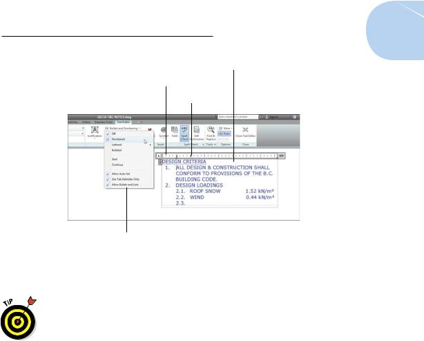
Mtext supports bulleted and numbered lists. This feature is especially useful for creating general drawing notes, as shown in Figure 13-6. AutoCAD automates the process of creating numbered lists almost completely. Here’s how:
1.Follow Steps 1 through 8 in the earlier section, “Making it with Mtext,” to open the In-Place Text Editor.
2.Type a title — for example, DESIGN CRITERIA.
If you want your title underlined, click Underline on the Formatting panel (or the Text Formatting toolbar) before you type the title; click Underline again to turn it off. Press Enter to go to the next line, and press Enter again to leave a little more space.
3.On the Paragraph panel of the Text Editor tab, click the Bullets and Numbering drop-down button; verify that Allow Auto-List, Use Tab Delimiter Only, and Allow Bullets and Lists are selected; then click Numbered, as shown in Figure 13-6.
The number 1 followed by a period appears on the current line, and the cursor jumps to the tab stop visible in the ruler at the top of the In-Place Text Editor window.
Enabling the Numbered option places numerals followed by periods in front of items in a list. (Bulleted places bullet characters in front of items in a list.) Allow Auto-List enables automatic numbering — each time you press Enter to move to a new line, AutoCAD increments the number.
4.Type the text corresponding to the current number or bullet.
As AutoCAD wraps the text, the second and subsequent lines align with the tab stop, and the text is indented automatically.
5.Press Enter at the end of the paragraph to move to the next line.
Just like creating numbered lists in your favorite word processor, AutoCAD automatically inserts the next number at the beginning of the new paragraph, with everything perfectly aligned.
To create nested numbered or bulleted items as shown in Figure 13-6, simply press Tab at the start of the line. If you change your mind, you can bump a nested text item up a level by selecting the item in the In-Place Text Editor and pressing Shift+Tab.
www.it-ebooks.info
Chapter 13: Text with Character 285
Indentation of second and subsequent lines
Indentation of rst line
Tab
In-Place Text Editor right-click
Figure 13-6: Tabs, indents, and automatic numbering are set to create numbered lists.
6. Repeat Steps 4 and 5 for each subsequent numbered or bulleted item.
For legibility, you sometimes want to add spaces between the notes. If you press Enter twice to give yourself a blank line, AutoCAD — like
every good word processor — thinks you’re finished with your list and turns numbering off. AutoCAD is smart, so you need to be smarter.
If you put the cursor at the end of the first note and press Enter, you get a blank line. The problem is, the blank line is now numbered, and your intended Note 2 is now Note 3. Just press the Backspace key. The number on the blank line disappears, and Note 2 is back to being Note 2 again. When you delete a numbered item, the remaining numbers adjust automatically.
If you don’t like the horizontal spacing of the numbers or the alignment of subsequent lines, you can adjust them easily by manipulating the tab and indent markers in the In-Place Text Editor’s ruler.
7.In the ruler, drag the upper slider (the triangle pointing down) to the right a short distance. Drag the lower slider (the triangle pointing up) a slightly greater distance to the right.
The upper slider controls the indentation of the first line in each paragraph. The lower slider controls the indentation of the second and subsequent lines. An indent of one to two of the short, vertical tick marks usually works well for the first line. An indent of two to four tick marks works well for the second and subsequent lines.
www.it-ebooks.info
286 Part III: If Drawings Could Talk
8.Click in the ruler just above the lower slider.
A small L appears above the lower slider. The L shows the tab stop.
Make sure that the corner of the L aligns horizontally with the point of the lower slider triangle. If not, click and drag the L until it aligns.
If you prefer to type tab and indent distances, not adjust them with the cursor, open the Paragraph dialog box by either
Clicking the little arrow at the right end of the Paragraph panel label (in AutoCADese, it’s called a Panel Dialog Box Launcher).
Right-clicking inside the In-Place Text Editor and choosing Paragraph.
Whichever way you do it, if you select text first, the tab and indent changes apply to the selected text. If you don’t select text first, the changes apply to new text from that point forward in the multiline text object.
Line up in columns — now!
The text functionality of AutoCAD is getting more and more word processor– like. A few releases back, it was simple indents; then came numbered and bulleted lists. The most recent addition is columns in multiline text.
Columns come in two flavors: static and dynamic.
Static: You specify the number of columns into which you want to flow your text. Columns are always the same height, and text is allowed to overflow the final column if there’s too much of it.
Dynamic: As you might expect, these columns are friendlier, more flexible, and the life of any party. You can individually adjust column heights, and new columns are added automatically to accommodate the text.
Selecting either column type also offers you a Column Settings dialog box where you can specify values numerically instead of by dragging grips.
Figure 13-7 shows a block of multiline text imported as an RTF file from a word processor and then formatted in dynamic columns with the Manual Height option.
www.it-ebooks.info

Chapter 13: Text with Character 287
Figure 13-7: Dynamically columnizing your text.
Setting up columns is pretty straightforward — the following steps explain how:
1.Open a drawing that contains a large multiline text object or create a large multiline text object in a new drawing.
If you already have drawing specifications or general notes in a wordprocessor document, or even a text file, you can right-click inside the MTEXT command’s In-Place Text Editor and choose Import Text. The Select File dialog box opens, giving you the choice of Rich Text Format (RTF) or ASCII text (TXT) files.
2.If the In-Place Text Editor isn’t already open, double-click the text, or select it, and then right-click and choose Mtext Edit.
3.Click Columns in the Insert panel and choose either Dynamic Columns or Static Columns.
If you choose Dynamic Columns, select either Auto Height or Manual Height. Selecting Manual Height puts grips on each column so you can adjust their height individually (refer to Figure 13-7). Auto Height displays a single grip — so the heights of all columns remain the same, but new columns are still added as required by the amount of text.
If you choose Static Columns, select the number of columns you want from the menu. Clicking 2, for example, creates two columns regardless of the length of your text — you may end up with overflowing text or empty columns.
4.Click Close Text Editor (or OK in the Text Formatting toolbar) when you’re satisfied with the column arrangement.
You can revert to a noncolumnar arrangement by clicking the Columns button in the Insert panel and choosing No Columns.
www.it-ebooks.info