

Chapter 7: Preciseliness Is Next to CADliness 159
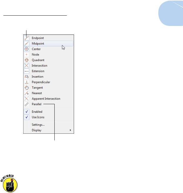
Active Object Snap mode
Inactive Object Snap mode
Figure 7-5: Grabbing multiple object features is an osnap.
For example, applying crosshatching rapidly becomes impossible if the boundary of the area you are hatching has even microscopic leaks.
Most, but not all, object snap overrides have Running Object Snap equivalents. For example, Endpoint, Midpoint, and Center work as either overrides or running object snaps, but Mid Between 2 Points works only in Override mode.
Other Practical Precision Procedures
The following are some other AutoCAD precision techniques (refer to Table 7-1):
www.it-ebooks.info
160 Part II: Let There Be Lines
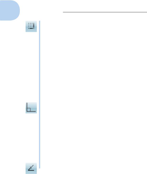
Snap: If you turn on Snap mode, AutoCAD constrains the crosshairs to an imaginary rectangular grid of points at the spacing that you’ve specified when AutoCAD prompts you to specify a point.
When you enable Snap mode, at first it seems to be broken because the cursor doesn’t snap to the imaginary grid but travels freely. It becomes active only when the program asks you to pick a point.
Follow these steps to turn on Snap mode:
1.Right-click the Snap Mode button on the status bar.
2.Choose Settings.
The Snap and Grid tab on the Drafting Settings dialog box appears.
3.Enter a snap spacing in the Snap X Spacing field and click OK.
Click the Snap Mode button on the status bar (labeled SNAP if your status bar buttons show text) or press F9 to toggle Snap mode off and on. To use Snap effectively, change the snap spacing frequently — changing to a smaller spacing as you zoom in and work on smaller areas.
You can switch between Grid Snap (that is, snap points in rows and columns) and PolarSnap (snap points based on distances and angles) by using the Snap Mode button’s shortcut menu. See the PolarSnap item later in this list for more info.
Ortho: Ortho mode forces the crosshairs to move horizontally or vertically relative to the current coordinate system’s X- and Y-axes. Click the Ortho Mode button (ORTHO for text buttons) on the status bar or press F8 to toggle Ortho mode. Because technical drawings often include lots of orthogonal lines, you may use Ortho mode a lot — but take a close look at polar tracking as well.
Direct distance entry (DDE): This point-and-type technique is an easy and efficient way to draw with precision. You simply point the crosshairs in a particular direction, type a distance value at the command line, and press Enter. You can use DDE any time the crosshairs are anchored to a point, and the command line or Dynamic Input tooltip prompts you for another point or a distance.
You’ll usually use DDE with Polar Tracking turned on to specify distances in particular directions (for example, in angle increments of 45 degrees). You can also combine DDE with Ortho mode to specify a distance in an orthogonal direction (0, 90, 180, or 270 degrees).
Object Snap Tracking: This feature extends running object snaps so that you can locate points based on more than one object snap point.
www.it-ebooks.info
Chapter 7: Preciseliness Is Next to CADliness 161
For example, you can define a point at the center of a square by tracking to the midpoints of two perpendicular sides. Click Object Snap Tracking on the status bar (if you’re showing text instead of icons, this button is labeled OTRACK — which has nothing at all to do with the Irish railway system) or press F11 to toggle Object Snap Tracking.
Polar Tracking: When you turn on Polar Tracking, the crosshairs jump to increments of the angle you specified in the Drafting Settings dialog box or chose on the right-click menu. When the crosshairs jump, a tooltip label starting with Polar: appears. Right-click the Polar Tracking button on the status bar (POLAR on buttons that show text labels) and choose the Settings option to display the Polar Tracking tab on the Drafting Settings dialog box. Select an angle from the Increment Angle drop-down list and then click OK. Click the Polar Tracking button on the status bar or press F10 to toggle Polar Tracking mode.
Remember, you can set a predefined Polar Tracking angle by rightclicking the Polar Tracking button and choosing it from the menu. If you want to add an angle that’s not on the list, you have to click Settings to open the Drafting Settings dialog box.
PolarSnap: You can force polar tracking to jump to specific incremental distances along the tracking angles by changing the snap type from Grid snap to PolarSnap. For example, if you turn on polar tracking and set
it to 45 degrees, and then turn on PolarSnap and set it to 2 units, polar tracking jumps to points that are at angle increments of 45 degrees and distance increments of 2 units from the previous point. PolarSnap has a similar effect on Object Snap tracking.
To activate PolarSnap, right-click the Snap Mode button and choose PolarSnap from the menu. To specify a PolarSnap distance, follow these steps:
1.Right-click the SNAP button on the status bar.
2.Choose Settings.
The Snap and Grid tab on the Drafting Settings dialog box appears.
3.Click the PolarSnap radio button, type a distance in the Polar Distance text box, and then click OK.
When you want to return to ordinary rectangular snap, as described at the beginning of this list, right-click the Snap Mode button and choose Grid Snap from the menu.
Temporary overrides: Settings such as SNAP, ORTHO, and POLAR remain on until you turn them off. You can also use temporary overrides, which last only as long as you hold down their key or key combination. For example, with Ortho turned off, holding down the Shift key puts AutoCAD into a temporary Ortho mode for as long as you press Shift. For additional information, visit the online help system.
www.it-ebooks.info
162 Part II: Let There Be Lines
If you’re new to AutoCAD, its wide range of precision tools probably seems overwhelming at this point. Rest assured that there’s more than one way to skin a cat precisely (with cats, accuracy is unimportant), and not everyone needs to understand all the ways. You can make perfectly precise drawings without using every single implement in AutoCAD’s precision toolkit. We recommend these steps:
1.Get comfortable with typing coordinates, Ortho mode, direct distance entry, and Object Snap overrides.
2.Become familiar with running object snaps and try Snap mode.
3.After you have all these precision features under your belt, feel free to experiment with Polar Tracking, PolarSnap, and Object Snap Tracking.
It’s easy to confuse the names of the snap and object snap (osnap) features. Remember that snap constrains the crosshairs to locations whose coordinates are multiples of the current snap spacing. Snap works whether or not there are objects in the drawing. Object snap (osnap) enables you to grab points on existing objects, whether or not those points happen to correspond with the snap spacing.
So what happens if some of your drawing-with-precision choices seem to contradict each other? Simple. AutoCAD goes with the one that took you the most effort to initiate. That is, Snap is overridden by Osnap, which is overridden by snap overrides, which is overridden by keyboard entry of points or distances.
www.it-ebooks.info
8
Along the Straight and Narrow
In This Chapter
Drawing linear things with the AutoCAD drawing commands
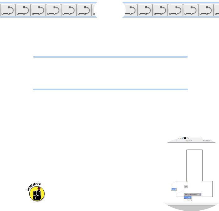
Lining up for lines and polylines
Closing up with rectangles and polygons
As you probably remember from your crayon-and-coloring-book days, drawing stuff is fun. CAD imposes a little more discipline, but draw-
ing stuff with AutoCAD is still fun (trust me on this one). In computer-aided drafting, you usually start by drawing geometry — shapes such as lines, circles, rectangles, and so on — that represents the real-world object that you’re documenting. This chapter shows you how to draw linear geometry — objects that proceed in a straightforward manner from one point to the next. In Chapter 9, we throw some curves at you.
After you’ve created some straight or curvy geometry, you’ll probably need to add some dimensions, text, and hatching, but those elements come later (in Part III of this book). Or you may want to use that geometry as the basis for some cool 3D modeling (we introduce you to that topic in Part V). Your first task is to get
the geometry right; then you can worry about labeling things.
Drawing geometry properly in AutoCAD depends on paying attention to object properties and the precision of the points that you specify to create the
objects. We cover these matters in Chapters 6 and 7, so if you eagerly jumped to this chapter to get right to the fun stuff, take a moment to review those chapters first.
www.it-ebooks.info