

- •About the Authors
- •Dedication
- •Authors’ Acknowledgments
- •Table of Contents
- •Introduction
- •What’s Not (And What Is) in This Book
- •Mac attack!
- •Who Do We Think You Are?
- •How This Book Is Organized
- •Part I: AutoCAD 101
- •Part II: Let There Be Lines
- •Part III: If Drawings Could Talk
- •Part IV: Advancing with AutoCAD
- •Part V: On a 3D Spree
- •Part VI: The Part of Tens
- •But wait . . . there’s more!
- •Icons Used in This Book
- •A Few Conventions — Just in Case
- •Commanding from the keyboard
- •Tying things up with the Ribbon
- •Where to Go from Here
- •Why AutoCAD?
- •The Importance of Being DWG
- •Seeing the LT
- •Checking System Requirements
- •Suddenly, It’s 2013!
- •AutoCAD Does Windows (And Office)
- •And They’re Off: AutoCAD’s Opening Screens
- •Running with Ribbons
- •Getting with the Program
- •Looking for Mr. Status Bar
- •Let your fingers do the talking: The command window
- •The key(board) to AutoCAD success
- •Keeping tabs on palettes
- •Down the main stretch: The drawing area
- •Fun with F1
- •A Simple Setup
- •Drawing a (Base) Plate
- •Drawing rectangles on the right layers
- •Circling your plate
- •Nuts to you
- •Getting a Closer Look with Zoom and Pan
- •Modifying to Make It Merrier
- •Hip-hip-array!
- •Stretching out
- •Crossing your hatches
- •Following the Plot
- •A Setup Roadmap
- •Choosing your units
- •Weighing up your scales
- •Thinking annotatively
- •Thinking about paper
- •Defending your border
- •A Template for Success
- •Making the Most of Model Space
- •Setting your units
- •Making the drawing area snap-py (and grid-dy)
- •Setting linetype and dimension scales
- •Entering drawing properties
- •Making Templates Your Own
- •Setting Up a Layout in Paper Space
- •Will that be tabs or buttons?
- •View layouts Quick(View)ly
- •Creating a layout
- •Copying and changing layouts
- •Lost in paper space
- •Spaced out
- •A view(port) for drawing in
- •About Paper Space Layouts and Plotting
- •Managing Your Properties
- •Layer one on me!
- •Accumulating properties
- •Creating new layers
- •Manipulating layers
- •Using Named Objects
- •Using AutoCAD DesignCenter
- •Copying layers between drawings
- •Controlling Your Precision
- •Keyboard capers: Coordinate input
- •Understanding AutoCAD’s coordinate systems
- •Grab an object and make it snappy
- •Other Practical Precision Procedures
- •Introducing the AutoCAD Drawing Commands
- •The Straight and Narrow: Lines, Polylines, and Polygons
- •Toeing the line
- •Connecting the lines with polyline
- •Squaring off with rectangles
- •Choosing your sides with polygon
- •(Throwing) Curves
- •Going full circle
- •Arc-y-ology
- •Solar ellipses
- •Splines: The sketchy, sinuous curves
- •Donuts: The circles with a difference
- •Revision clouds on the horizon
- •Scoring Points
- •Commanding and Selecting
- •Command-first editing
- •Selection-first editing
- •Direct object manipulation
- •Choosing an editing style
- •Grab It
- •One-by-one selection
- •Selection boxes left and right
- •Perfecting Selecting
- •AutoCAD Groupies
- •Object Selection: Now You See It . . .
- •Get a Grip
- •About grips
- •A gripping example
- •Move it!
- •Copy, or a kinder, gentler Move
- •A warm-up stretch
- •Your AutoCAD Toolkit
- •The Big Three: Move, Copy, and Stretch
- •Base points and displacements
- •Move
- •Copy
- •Copy between drawings
- •Stretch
- •More Manipulations
- •Mirror
- •Rotate
- •Scale
- •Array
- •Offset
- •Slicing, Dicing, and Splicing
- •Trim and Extend
- •Break
- •Fillet and Chamfer and Blend
- •Join
- •When Editing Goes Bad
- •Zoom and Pan with Glass and Hand
- •The wheel deal
- •Navigating your drawing
- •Controlling your cube
- •Time to zoom
- •A View by Any Other Name . . .
- •Looking Around in Layout Land
- •Degenerating and Regenerating
- •Getting Ready to Write
- •Simply stylish text
- •Taking your text to new heights
- •One line or two?
- •Your text will be justified
- •Using the Same Old Line
- •Turning On Your Annotative Objects
- •Saying More in Multiline Text
- •Making it with Mtext
- •It slices; it dices . . .
- •Doing a number on your Mtext lists
- •Line up in columns — now!
- •Modifying Mtext
- •Gather Round the Tables
- •Tables have style, too
- •Creating and editing tables
- •Take Me to Your Leader
- •Electing a leader
- •Multi options for multileaders
- •How Do You Measure Up?
- •A Field Guide to Dimensions
- •The lazy drafter jumps over to the quick dimension commands
- •Dimension associativity
- •Where, oh where, do my dimensions go?
- •The Latest Styles in Dimensioning
- •Creating and managing dimension styles
- •Let’s get stylish!
- •Adjusting style settings
- •Size Matters
- •Details at other scales
- •Editing Dimensions
- •Editing dimension geometry
- •Editing dimension text
- •Controlling and editing dimension associativity
- •Batten Down the Hatches!
- •Don’t Count Your Hatches. . .
- •Size Matters!
- •We can do this the hard way. . .
- •. . . or we can do this the easy way
- •Annotative versus non-annotative
- •Pushing the Boundary (Of) Hatch
- •Your hatching has no style!
- •Hatch from scratch
- •Editing Hatch Objects
- •You Say Printing, We Say Plotting
- •The Plot Quickens
- •Plotting success in 16 steps
- •Get with the system
- •Configure it out
- •Preview one, two
- •Instead of fit, scale it
- •Plotting the Layout of the Land
- •Plotting Lineweights and Colors
- •Plotting with style
- •Plotting through thick and thin
- •Plotting in color
- •It’s a (Page) Setup!
- •Continuing the Plot Dialog
- •The Plot Sickens
- •Rocking with Blocks
- •Creating Block Definitions
- •Inserting Blocks
- •Attributes: Fill-in-the-Blank Blocks
- •Creating attribute definitions
- •Defining blocks that contain attribute definitions
- •Inserting blocks that contain attribute definitions
- •Edit attribute values
- •Extracting data
- •Exploding Blocks
- •Purging Unused Block Definitions
- •Arraying Associatively
- •Comparing the old and new ARRAY commands
- •Hip, hip, array!
- •Associatively editing
- •Going External
- •Becoming attached to your xrefs
- •Layer-palooza
- •Creating and editing an external reference file
- •Forging an xref path
- •Managing xrefs
- •Blocks, Xrefs, and Drawing Organization
- •Mastering the Raster
- •Attaching a raster image
- •Maintaining your image
- •Theme and Variations: Dynamic Blocks
- •Lights! Parameters!! Actions!!!
- •Manipulating dynamic blocks
- •Maintaining Design Intent
- •Defining terms
- •Forget about drawing with precision!
- •Constrain yourself
- •Understanding Geometric Constraints
- •Applying a little more constraint
- •AutoConstrain yourself!
- •Understanding Dimensional Constraints
- •Practice a little constraint
- •Making your drawing even smarter
- •Using the Parameters Manager
- •Dimensions or constraints — have it both ways!
- •The Internet and AutoCAD: An Overview
- •You send me
- •Send it with eTransmit
- •Rapid eTransmit
- •Bad reception?
- •Help from the Reference Manager
- •Design Web Format — Not Just for the Web
- •All about DWF and DWFx
- •Autodesk Design Review 2013
- •The Drawing Protection Racket
- •Autodesk Weather Forecast: Increasing Cloud
- •Working Solidly in the Cloud
- •Free AutoCAD!
- •Going once, going twice, going 123D
- •Your head planted firmly in the cloud
- •The pros
- •The cons
- •Cloudy with a shower of DWGs
- •AutoCAD 2013 cloud connectivity
- •Tomorrow’s Forecast
- •Understanding 3D Digital Models
- •Tools of the Trade
- •Warp speed ahead
- •Entering the third dimension
- •Untying the Ribbon and opening some palettes
- •Modeling from Above
- •Using 3D coordinate input
- •Using point filters
- •Object snaps and object snap tracking
- •Changing Planes
- •Displaying the UCS icon
- •Adjusting the UCS
- •Navigating the 3D Waters
- •Orbit à go-go
- •Taking a spin around the cube
- •Grabbing the SteeringWheels
- •Visualizing 3D Objects
- •Getting Your 3D Bearings
- •Creating a better 3D template
- •Seeing the world from new viewpoints
- •From Drawing to Modeling in 3D
- •Drawing basic 3D objects
- •Gaining a solid foundation
- •Drawing solid primitives
- •Adding the Third Dimension to 2D Objects
- •Creating 3D objects from 2D drawings
- •Modifying 3D Objects
- •Selecting subobjects
- •Working with gizmos
- •More 3D variants of 2D commands
- •Editing solids
- •Get the 2D Out of Here!
- •A different point of view
- •But wait! There’s more!
- •But wait! There’s less!
- •Do You See What I See?
- •Visualizing the Digital World
- •Adding Lighting
- •Default lighting
- •User-defined lights
- •Sunlight
- •Creating and Applying Materials
- •Defining a Background
- •Rendering a 3D Model
- •Autodesk Feedback Community
- •Autodesk Discussion Groups
- •Autodesk’s Own Bloggers
- •Autodesk University
- •The Autodesk Channel on YouTube
- •The World Wide (CAD) Web
- •Your Local ATC
- •Your Local User Group
- •AUGI
- •Books
- •Price
- •3D Abilities
- •Customization Options
- •Network Licensing
- •Express Tools
- •Parametrics
- •Standards Checking
- •Data Extraction
- •MLINE versus DLINE
- •Profiles
- •Reference Manager
- •And The Good News Is . . .
- •APERTURE
- •DIMASSOC
- •MENUBAR
- •MIRRTEXT
- •OSNAPZ
- •PICKBOX
- •REMEMBERFOLDERS
- •ROLLOVERTIPS
- •TOOLTIPS
- •VISRETAIN
- •And the Bonus Round
- •Index

Chapter 13: Text with Character 293
www.cadalyst.com/cad/autocad/tell-me-all-you-know- attribute-extraction-part-1-learning-curve-autocad- tutorial-6271
www.cadalyst.com/cad/autocad/tell-me-all-you-know- and-even-more-advanced-attribute-extraction-part- 2-learning-curve-a
Take Me to Your Leader
Don’t worry; we’re not space aliens, popular opinion to the contrary. No, we’re talking about those notes with arrows that point to drawing objects that you need to embellish with some verbiage.
Multileaders — mleaders for short — are a vast improvement over old-style leaders available prior to AutoCAD 2008. In fact, they’re so good, they should be running the United Nations! Mleaders, unlike the old-style leaders, are single objects. They are also able to point in multiple directions at once (just don’t ask them which way is the bus station). Finally, multileaders — just like text, dimensions, hatching, and other objects you use to document your drawing — can be annotative.
There are two older-style leaders stored in AutoCAD’s attic (Autodesk hates to throw anything away, because sure as blazes someone will complain that they still need it for a custom menu macro they created twenty years ago and use all the time). These semiretired leaders are no longer accessible on menus or toolbars, but they’re still lurking up there waiting to . . . er, lead you astray. If you’ve become attached to typing commands, you may be inclined to type either LEADER or LE to create those pointy-headed thingies. If you do, be aware that LEADER runs the positively ancient command for creating notes-with-arrows. There are no options, so only straight leader lines and infinitely long text strings are what you get. LE (the alias for the QLEADER command) runs the merely elderly command for creating notes-with-arrows; this one has a Settings dialog box where you can set some options, and it does ask you to specify a width for your Mtext note. However, unlike multileaders, both LEADER and LE create the leader lines and the text as two separate objects. The main reason for mentioning them here is that you’ll probably run into them in older drawings.
Electing a leader
You can draw multileader objects that consist of leader lines and multiline text at the same time by using the MLEADER command, as described in the following steps:
www.it-ebooks.info
294 Part III: If Drawings Could Talk
1.Set a multileader style — one that’s appropriate for your needs — current.
Choose an existing style from the Multileader Style drop-down list on the Home tab’s Annotation panel slideout, or create a new style by clicking the Multileader Style button on the Annotation slideout. Visit the online help for tips on creating new multileader styles.
2.Choose Multileader from the Annotation panel.
The command line prompts you to select the location for the pointy end of the leader arrowhead:
Specify leader arrowhead location or [leader Landing first/Content first/Options] <Options>:
The initial default method is to locate the arrowhead followed by the leader landing (that is, the short horizontal line between the leader line and the text), at which point AutoCAD displays the In-Place Text Editor, and you enter the text of your note. If you’d rather place the leader landing first, type L and press Enter. If you’d rather type the content first, type C and press Enter.
If you want to draw spline-curved rather than straight leader lines, specify the number of pick points for the leader lines and press Enter to display multileader options at the command line or the Dynamic Input tooltip. Refer to the online help for more information on the command options.
3.Pick a location in the drawing that you want the leader to point to.
If you use an object snap mode, such as Nearest or Midpoint, to pick a point on an object, AutoCAD associates the leader with the object. If you later move the object, AutoCAD updates the leader so that it points to the new location.
The command line prompts you for the next point.
4.Pick a second point.
AutoCAD draws a shaft from the arrowhead to this point.
If you pick a second point that’s too close to the arrowhead point and AutoCAD doesn’t have enough room to draw the arrowhead, it omits the arrowhead.
By default, AutoCAD lets you pick two points for the leader line: The first point locates the arrowhead, and the second point locates the start of the short horizontal leader landing. If you need more points than that, restart the command and choose Options, Maxpoints and set a new value.
After you pick the point for the leader landing, AutoCAD opens the In-Place Text Editor.
www.it-ebooks.info
Chapter 13: Text with Character 295
5.Type your text.
You’re now in the same In-Place Text Editor we describe earlier in this chapter, with the same Text Editor tab and options.
6.Click Close.
The In-Place Text Editor window closes and adds your text to the drawing, next to the leader.
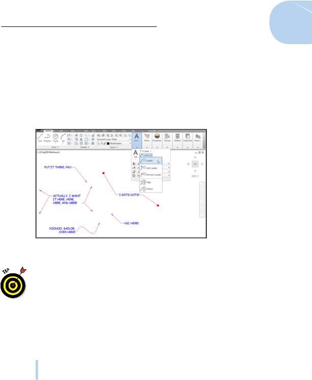
Figure 13-10 shows several different leaders with notes.
Figure 13-10: No loss for (multi)leaders.
You can use grips to manipulate a multileader’s individual components, just as if it were several objects instead of a single object. Hold down the Ctrl key and click a multileader to select different pieces. You can even use grips to adjust the width of multileader text as if it were a plain everyday Mtext object.
Multi options for multileaders
In addition to the MLEADER command itself, which we walk you through in the preceding steps, multileaders come with a slew of formatting, drawing, and editing commands:
MLEADEREDIT: Use this command to add or remove leader lines from multileader objects. You’ll find each of those functions on the Multileader drop-down list (refer to Figure 13-10).
www.it-ebooks.info
296 Part III: If Drawings Could Talk
MLEADERSTYLE: Multileaders, like text, tables, and dimensions, are formatted according to named styles. To display the Multileader Style Manager dialog box (which looks a lot like a simplified version of the Dimension Style Manager) click Multileader Style on the Home tab’s Annotation slideout.
MLEADERALIGN: A tedious chore in earlier AutoCAD versions was getting all the leaders to line up; it usually involved drawing a construction line and then using object snaps to move common points on the leaders to the construction line. To line up multileaders, choose Align from the Multileader drop-down list.
MLEADERCOLLECT: Multileaders can contain blocks as well as text (we cover blocks in Chapter 17). Choose Collect from the Multileader dropdown list to gather a group of leaders containing blocks; they’ll rearrange themselves as a single multileader containing the multiple blocks.
For more information on any of these commands, look them up by name in the Command Reference section of the online help.
Multileaders and multileader styles can be annotative or non-annotative. Making them annotative and assigning appropriate annotation scales is a huge timesaver for creating them initially and for creating detail views at different scales.
www.it-ebooks.info
14
Entering New Dimensions
In This Chapter
Placing dimensions in drawings
Choosing a dimensioning method
Creating and modifying your own dimension styles
Adjusting dimension sizes to suit the drawing plot scale
Placing and modifying annotative dimensions, including details at other scales
Modifying dimensions
In drafting — either CAD or manual drafting — dimensions are special text labels with attached lines that together clearly indicate the size of
something. Although it’s theoretically possible to draw all the pieces of each dimension by using AutoCAD commands, such as LINE and MTEXT, dimensioning is so common of a drafting task that AutoCAD
provides special commands for doing the job more efficiently. These dimensioning commands group the parts of each dimension into a convenient, easy-to-edit package much like a block. In fact, AutoCAD actually produces each dimension as something it calls an anonymous block. We discuss blocks in Chapter 17.
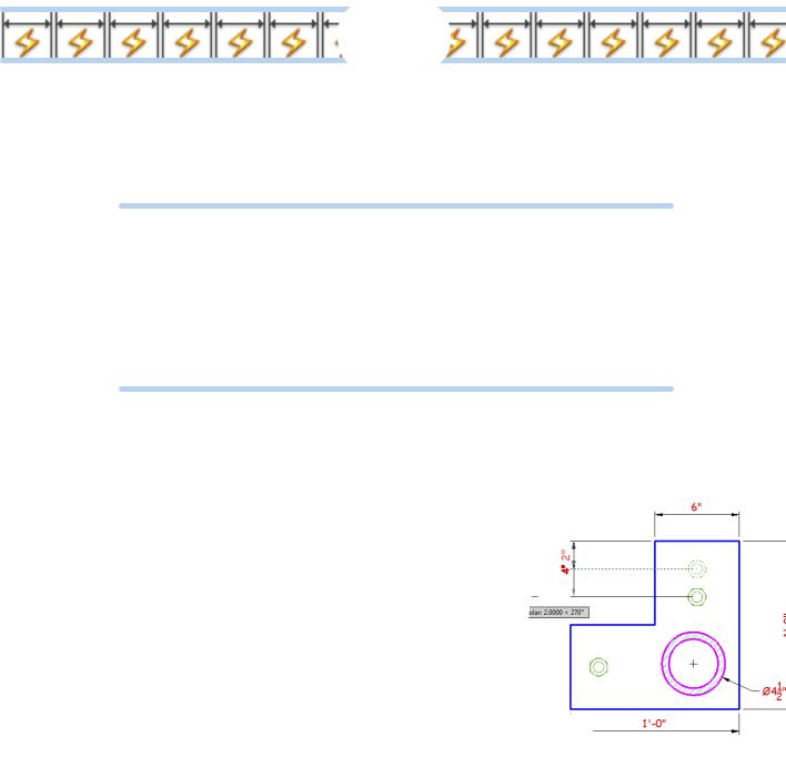
Even better, as you edit an object — by stretching a line, for example — AutoCAD automatically updates the measurement displayed in the dimension text label to indicate the object’s new size, as shown in Figure 14-1. And perhaps best of all, AutoCAD’s annotative dimensions adjust their text height and arrowhead size automatically to suit the annotation scale on
the model tab or the viewport scale in a layout. We explain the general principles of annotative objects in Chapters 13 and
15; in this chapter, we take a close look at annotative dimensions.
www.it-ebooks.info