

- •About the Authors
- •Dedication
- •Authors’ Acknowledgments
- •Table of Contents
- •Introduction
- •What’s Not (And What Is) in This Book
- •Mac attack!
- •Who Do We Think You Are?
- •How This Book Is Organized
- •Part I: AutoCAD 101
- •Part II: Let There Be Lines
- •Part III: If Drawings Could Talk
- •Part IV: Advancing with AutoCAD
- •Part V: On a 3D Spree
- •Part VI: The Part of Tens
- •But wait . . . there’s more!
- •Icons Used in This Book
- •A Few Conventions — Just in Case
- •Commanding from the keyboard
- •Tying things up with the Ribbon
- •Where to Go from Here
- •Why AutoCAD?
- •The Importance of Being DWG
- •Seeing the LT
- •Checking System Requirements
- •Suddenly, It’s 2013!
- •AutoCAD Does Windows (And Office)
- •And They’re Off: AutoCAD’s Opening Screens
- •Running with Ribbons
- •Getting with the Program
- •Looking for Mr. Status Bar
- •Let your fingers do the talking: The command window
- •The key(board) to AutoCAD success
- •Keeping tabs on palettes
- •Down the main stretch: The drawing area
- •Fun with F1
- •A Simple Setup
- •Drawing a (Base) Plate
- •Drawing rectangles on the right layers
- •Circling your plate
- •Nuts to you
- •Getting a Closer Look with Zoom and Pan
- •Modifying to Make It Merrier
- •Hip-hip-array!
- •Stretching out
- •Crossing your hatches
- •Following the Plot
- •A Setup Roadmap
- •Choosing your units
- •Weighing up your scales
- •Thinking annotatively
- •Thinking about paper
- •Defending your border
- •A Template for Success
- •Making the Most of Model Space
- •Setting your units
- •Making the drawing area snap-py (and grid-dy)
- •Setting linetype and dimension scales
- •Entering drawing properties
- •Making Templates Your Own
- •Setting Up a Layout in Paper Space
- •Will that be tabs or buttons?
- •View layouts Quick(View)ly
- •Creating a layout
- •Copying and changing layouts
- •Lost in paper space
- •Spaced out
- •A view(port) for drawing in
- •About Paper Space Layouts and Plotting
- •Managing Your Properties
- •Layer one on me!
- •Accumulating properties
- •Creating new layers
- •Manipulating layers
- •Using Named Objects
- •Using AutoCAD DesignCenter
- •Copying layers between drawings
- •Controlling Your Precision
- •Keyboard capers: Coordinate input
- •Understanding AutoCAD’s coordinate systems
- •Grab an object and make it snappy
- •Other Practical Precision Procedures
- •Introducing the AutoCAD Drawing Commands
- •The Straight and Narrow: Lines, Polylines, and Polygons
- •Toeing the line
- •Connecting the lines with polyline
- •Squaring off with rectangles
- •Choosing your sides with polygon
- •(Throwing) Curves
- •Going full circle
- •Arc-y-ology
- •Solar ellipses
- •Splines: The sketchy, sinuous curves
- •Donuts: The circles with a difference
- •Revision clouds on the horizon
- •Scoring Points
- •Commanding and Selecting
- •Command-first editing
- •Selection-first editing
- •Direct object manipulation
- •Choosing an editing style
- •Grab It
- •One-by-one selection
- •Selection boxes left and right
- •Perfecting Selecting
- •AutoCAD Groupies
- •Object Selection: Now You See It . . .
- •Get a Grip
- •About grips
- •A gripping example
- •Move it!
- •Copy, or a kinder, gentler Move
- •A warm-up stretch
- •Your AutoCAD Toolkit
- •The Big Three: Move, Copy, and Stretch
- •Base points and displacements
- •Move
- •Copy
- •Copy between drawings
- •Stretch
- •More Manipulations
- •Mirror
- •Rotate
- •Scale
- •Array
- •Offset
- •Slicing, Dicing, and Splicing
- •Trim and Extend
- •Break
- •Fillet and Chamfer and Blend
- •Join
- •When Editing Goes Bad
- •Zoom and Pan with Glass and Hand
- •The wheel deal
- •Navigating your drawing
- •Controlling your cube
- •Time to zoom
- •A View by Any Other Name . . .
- •Looking Around in Layout Land
- •Degenerating and Regenerating
- •Getting Ready to Write
- •Simply stylish text
- •Taking your text to new heights
- •One line or two?
- •Your text will be justified
- •Using the Same Old Line
- •Turning On Your Annotative Objects
- •Saying More in Multiline Text
- •Making it with Mtext
- •It slices; it dices . . .
- •Doing a number on your Mtext lists
- •Line up in columns — now!
- •Modifying Mtext
- •Gather Round the Tables
- •Tables have style, too
- •Creating and editing tables
- •Take Me to Your Leader
- •Electing a leader
- •Multi options for multileaders
- •How Do You Measure Up?
- •A Field Guide to Dimensions
- •The lazy drafter jumps over to the quick dimension commands
- •Dimension associativity
- •Where, oh where, do my dimensions go?
- •The Latest Styles in Dimensioning
- •Creating and managing dimension styles
- •Let’s get stylish!
- •Adjusting style settings
- •Size Matters
- •Details at other scales
- •Editing Dimensions
- •Editing dimension geometry
- •Editing dimension text
- •Controlling and editing dimension associativity
- •Batten Down the Hatches!
- •Don’t Count Your Hatches. . .
- •Size Matters!
- •We can do this the hard way. . .
- •. . . or we can do this the easy way
- •Annotative versus non-annotative
- •Pushing the Boundary (Of) Hatch
- •Your hatching has no style!
- •Hatch from scratch
- •Editing Hatch Objects
- •You Say Printing, We Say Plotting
- •The Plot Quickens
- •Plotting success in 16 steps
- •Get with the system
- •Configure it out
- •Preview one, two
- •Instead of fit, scale it
- •Plotting the Layout of the Land
- •Plotting Lineweights and Colors
- •Plotting with style
- •Plotting through thick and thin
- •Plotting in color
- •It’s a (Page) Setup!
- •Continuing the Plot Dialog
- •The Plot Sickens
- •Rocking with Blocks
- •Creating Block Definitions
- •Inserting Blocks
- •Attributes: Fill-in-the-Blank Blocks
- •Creating attribute definitions
- •Defining blocks that contain attribute definitions
- •Inserting blocks that contain attribute definitions
- •Edit attribute values
- •Extracting data
- •Exploding Blocks
- •Purging Unused Block Definitions
- •Arraying Associatively
- •Comparing the old and new ARRAY commands
- •Hip, hip, array!
- •Associatively editing
- •Going External
- •Becoming attached to your xrefs
- •Layer-palooza
- •Creating and editing an external reference file
- •Forging an xref path
- •Managing xrefs
- •Blocks, Xrefs, and Drawing Organization
- •Mastering the Raster
- •Attaching a raster image
- •Maintaining your image
- •Theme and Variations: Dynamic Blocks
- •Lights! Parameters!! Actions!!!
- •Manipulating dynamic blocks
- •Maintaining Design Intent
- •Defining terms
- •Forget about drawing with precision!
- •Constrain yourself
- •Understanding Geometric Constraints
- •Applying a little more constraint
- •AutoConstrain yourself!
- •Understanding Dimensional Constraints
- •Practice a little constraint
- •Making your drawing even smarter
- •Using the Parameters Manager
- •Dimensions or constraints — have it both ways!
- •The Internet and AutoCAD: An Overview
- •You send me
- •Send it with eTransmit
- •Rapid eTransmit
- •Bad reception?
- •Help from the Reference Manager
- •Design Web Format — Not Just for the Web
- •All about DWF and DWFx
- •Autodesk Design Review 2013
- •The Drawing Protection Racket
- •Autodesk Weather Forecast: Increasing Cloud
- •Working Solidly in the Cloud
- •Free AutoCAD!
- •Going once, going twice, going 123D
- •Your head planted firmly in the cloud
- •The pros
- •The cons
- •Cloudy with a shower of DWGs
- •AutoCAD 2013 cloud connectivity
- •Tomorrow’s Forecast
- •Understanding 3D Digital Models
- •Tools of the Trade
- •Warp speed ahead
- •Entering the third dimension
- •Untying the Ribbon and opening some palettes
- •Modeling from Above
- •Using 3D coordinate input
- •Using point filters
- •Object snaps and object snap tracking
- •Changing Planes
- •Displaying the UCS icon
- •Adjusting the UCS
- •Navigating the 3D Waters
- •Orbit à go-go
- •Taking a spin around the cube
- •Grabbing the SteeringWheels
- •Visualizing 3D Objects
- •Getting Your 3D Bearings
- •Creating a better 3D template
- •Seeing the world from new viewpoints
- •From Drawing to Modeling in 3D
- •Drawing basic 3D objects
- •Gaining a solid foundation
- •Drawing solid primitives
- •Adding the Third Dimension to 2D Objects
- •Creating 3D objects from 2D drawings
- •Modifying 3D Objects
- •Selecting subobjects
- •Working with gizmos
- •More 3D variants of 2D commands
- •Editing solids
- •Get the 2D Out of Here!
- •A different point of view
- •But wait! There’s more!
- •But wait! There’s less!
- •Do You See What I See?
- •Visualizing the Digital World
- •Adding Lighting
- •Default lighting
- •User-defined lights
- •Sunlight
- •Creating and Applying Materials
- •Defining a Background
- •Rendering a 3D Model
- •Autodesk Feedback Community
- •Autodesk Discussion Groups
- •Autodesk’s Own Bloggers
- •Autodesk University
- •The Autodesk Channel on YouTube
- •The World Wide (CAD) Web
- •Your Local ATC
- •Your Local User Group
- •AUGI
- •Books
- •Price
- •3D Abilities
- •Customization Options
- •Network Licensing
- •Express Tools
- •Parametrics
- •Standards Checking
- •Data Extraction
- •MLINE versus DLINE
- •Profiles
- •Reference Manager
- •And The Good News Is . . .
- •APERTURE
- •DIMASSOC
- •MENUBAR
- •MIRRTEXT
- •OSNAPZ
- •PICKBOX
- •REMEMBERFOLDERS
- •ROLLOVERTIPS
- •TOOLTIPS
- •VISRETAIN
- •And the Bonus Round
- •Index
Chapter 21: It’s a 3D World After All 473
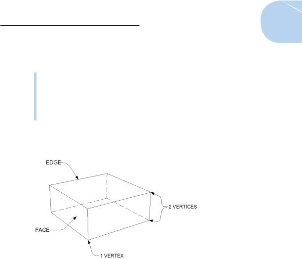
Although surface and solid models are created and modified differently, the 3D objects that make up the models are made up of the same subobjects. The subobjects that a 3D object is made up of are
Vertex: The 3D equivalent of an AutoCAD point object. Vertices are defined by a single X, Y, Z coordinate that can exist anywhere in 3D space and are located where the edges of a 3D object meet.
Edge: The boundary of a face, as defined by two X, Y, Z coordinates, one at each vertex.
Face: The surface area bounded by three or more edges.
Figure 21-1 shows a simple 3D object — a six-sided cubic shape created with the AutoCAD BOX command — and its subobjects.
Figure 21-1: Subobjects of a 3D object.
Tools of the Trade
AutoCAD includes a plethora of tools for creating, editing, viewing, and visualizing 3D models. You can find the most commonly used tools for 3D modeling on the 3D Modeling workspace’s Ribbon.
AutoCAD comes with two 3D workspaces: 3D Modeling and 3D Basics. We suppose the idea is that if you’re new to 3D, you get your feet wet with the 3D Basics workspace and then graduate to the 3D Modeling workspace after you gain some experience. Personally, we think the 3D Basics workspace is a waste of time; our preference is to have the whole enchilada available from the getgo. For this book, we work exclusively with the 3D Modeling workspace.
www.it-ebooks.info

474 Part V: On a 3D Spree
AutoCAD’s 3D environment is a lot like its 2D version, but there are some important differences. You should be aware of the following program settings and elements:
Hardware Acceleration: Graphics functions, such as changing visual styles and running 3D Orbit, can be processed on the main CPU — or, if hardware acceleration is enabled, on the graphics card itself. Turning on hardware acceleration, if your graphics card supports it, (which we cover in the next section) nearly always improves 3D performance.
Workspaces: AutoCAD 2013 comes with two 3D workspaces. We highly recommend that you use the 3D Modeling workspace. (We introduce workspaces in Chapter 2.) For more about the tools in the 3D Modeling workspace, see “Entering the third dimension,” later in this chapter.
Drawing Window: The drawing window’s background, crosshairs, and dynamic tooltip colors change when you switch between 2D and 3D views, and in 3D views, when you switch between parallel and perspective projection. Click Options on the Application Menu, click the Display tab, and then click the Colors button to access color settings for the different interface elements. Note that we’ve tweaked the background colors on our systems so they’re clearer on the printed page. Unless you’ve made changes already, you’ll be looking at a very dark gray background, rather than the light gray one in this chapter’s figures.
UCS Icon: When working in 3D, the UCS icon shows the orientation of the current X, Y plane and the direction of the Z axis. For information on using the UCS icon, see “Changing Planes,” later in this chapter.
Prior to AutoCAD 2012, the UCS icon merely showed you the orientation of the X, Y, and Z axes. If you used the UCS command to set a new UCS, the icon reoriented itself accordingly. Starting in AutoCAD 2012, the selectable UCS icon is in the driver’s seat — you can directly manipulate the icon to change the UCS. We introduce you to the new UCS icon in the “Changing Planes” section, later in the chapter.
Warp speed ahead
When you start AutoCAD for the first time after installing it, the program assesses your computer’s graphics card, and — if it’s up to the task — enables hardware acceleration. With hardware acceleration, you can change the view of your model — even models with lighting and applied materials — in real time, without any deterioration in quality. Hardware acceleration also boosts the overall visual quality of drawing objects as well as regeneration performance.
Autodesk tests a wide range of cards and drivers with each new release. To find out whether your graphics card is supported for AutoCAD, check out the graphics hardware list online at
www.it-ebooks.info
Chapter 21: It’s a 3D World After All 475
www.autodesk.com/autocad-graphicscard
Entering the third dimension
If you’re new to the 3D game and you’ve been working in 2D up until now, you need to do a couple of things before you can start a new 3D model in AutoCAD. You have to change the workspace and then you have to open a new file by using a 3D template. The following steps explain how:
1.Open the Workspaces drop-down list on the Quick Access Toolbar, or click the Workspace Switching button on the status bar and then choose 3D Modeling.
Toolbars, palettes, and Ribbon panels flash on and off, and soon AutoCAD settles down to display the Ribbon, as configured for the 3D Modeling workspace with a few additional panels.
2.Click the Application button and choose New; then click Drawing.
The Select Template dialog box appears.
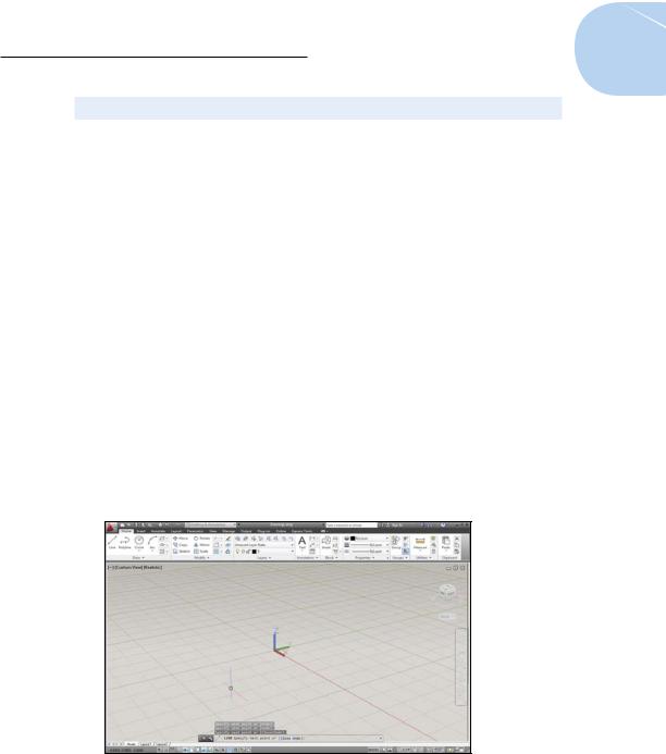
3.Choose acad3d.dwt if you’re working in imperial units or acadiso3d.dwt if you’re working in metric. Click Open.
A 3D modeling space appears (see Figure 21-2) where, instead of looking straight down at the drawing area, you look at it at an angle from above.
Figure 21-2: Ascending the Z axis.
4. To switch from 3D to the 2D world, simply reverse the steps just given.
www.it-ebooks.info

476 Part V: On a 3D Spree
Untying the Ribbon and opening some palettes
Most of AutoCAD 3D modeling tools can be accessed from the Ribbon and 3D–related palettes. The following list introduces you to the Ribbon tabs and palettes available in the 3D Modeling workspace. (Note that not all items in this list are visible in Figure 21-2 and that this list omits some items that are not unique to 3D.)
Home tab: Contains a subset of the most frequently used 3D tools for creating and editing solids, surfaces, and meshes; as well as user coordinate system command options, view tools, 2D drawing and editing commands, and layer and group tools.
Solid tab: Contains tools for creating and modifying 3D solids. We show you some of the finer points of solid modeling in Chapter 22.
Surface tab: Contains tools used to create, edit, and analyze NURBS surfaces.
Mesh tab: Contains tools used to create and modify meshes, convert them to solids, and generate live sections.
Render tab: Contains tools to add lighting and materials to a 3D model, and generate rendered output. Chapter 23 presents the basics of rendering in AutoCAD.
View tab: Contains tools to navigate, visualize, and change the current view and UCS of a 3D model. We cover navigation tools, coordinate systems, and visual styles in this chapter.
Output tab: Contains tools to output a 3D model to a DWF or PDF file or even generate a 3D print. We cover plotting 2D drawings in Chapter 16, and outputting 3D designs to paper isn’t significantly different (see the online help for specifics). We don’t cover exporting to 3D DWF or 3D printing in this book.
Plug-ins tab: Contains the Inventor Fusion panel with the single Edit in Fusion button. Inventor Fusion is a free-standing 3D modeling application installed (optionally) with AutoCAD 2013. The Inventor Fusion plug-in lets you select 3D objects from your AutoCAD drawing, edit them in Fusion, and then return to AutoCAD when you’re done. The prime feature of Fusion is that you can create and edit flowing, free-form solids — such as the body of a hair dryer — that would be extremely difficult, or even impossible, in AutoCAD.
The following palettes are found on the View tab of the Ribbon:
Materials Browser palette: Use to apply materials to the objects in the current model, and to manage materials in saved material libraries.
Materials Editor palette: Use to apply, create, and modify materials in the current model. Chapter 23 introduces you to materials.
www.it-ebooks.info