

- •About the Authors
- •Dedication
- •Authors’ Acknowledgments
- •Table of Contents
- •Introduction
- •What’s Not (And What Is) in This Book
- •Mac attack!
- •Who Do We Think You Are?
- •How This Book Is Organized
- •Part I: AutoCAD 101
- •Part II: Let There Be Lines
- •Part III: If Drawings Could Talk
- •Part IV: Advancing with AutoCAD
- •Part V: On a 3D Spree
- •Part VI: The Part of Tens
- •But wait . . . there’s more!
- •Icons Used in This Book
- •A Few Conventions — Just in Case
- •Commanding from the keyboard
- •Tying things up with the Ribbon
- •Where to Go from Here
- •Why AutoCAD?
- •The Importance of Being DWG
- •Seeing the LT
- •Checking System Requirements
- •Suddenly, It’s 2013!
- •AutoCAD Does Windows (And Office)
- •And They’re Off: AutoCAD’s Opening Screens
- •Running with Ribbons
- •Getting with the Program
- •Looking for Mr. Status Bar
- •Let your fingers do the talking: The command window
- •The key(board) to AutoCAD success
- •Keeping tabs on palettes
- •Down the main stretch: The drawing area
- •Fun with F1
- •A Simple Setup
- •Drawing a (Base) Plate
- •Drawing rectangles on the right layers
- •Circling your plate
- •Nuts to you
- •Getting a Closer Look with Zoom and Pan
- •Modifying to Make It Merrier
- •Hip-hip-array!
- •Stretching out
- •Crossing your hatches
- •Following the Plot
- •A Setup Roadmap
- •Choosing your units
- •Weighing up your scales
- •Thinking annotatively
- •Thinking about paper
- •Defending your border
- •A Template for Success
- •Making the Most of Model Space
- •Setting your units
- •Making the drawing area snap-py (and grid-dy)
- •Setting linetype and dimension scales
- •Entering drawing properties
- •Making Templates Your Own
- •Setting Up a Layout in Paper Space
- •Will that be tabs or buttons?
- •View layouts Quick(View)ly
- •Creating a layout
- •Copying and changing layouts
- •Lost in paper space
- •Spaced out
- •A view(port) for drawing in
- •About Paper Space Layouts and Plotting
- •Managing Your Properties
- •Layer one on me!
- •Accumulating properties
- •Creating new layers
- •Manipulating layers
- •Using Named Objects
- •Using AutoCAD DesignCenter
- •Copying layers between drawings
- •Controlling Your Precision
- •Keyboard capers: Coordinate input
- •Understanding AutoCAD’s coordinate systems
- •Grab an object and make it snappy
- •Other Practical Precision Procedures
- •Introducing the AutoCAD Drawing Commands
- •The Straight and Narrow: Lines, Polylines, and Polygons
- •Toeing the line
- •Connecting the lines with polyline
- •Squaring off with rectangles
- •Choosing your sides with polygon
- •(Throwing) Curves
- •Going full circle
- •Arc-y-ology
- •Solar ellipses
- •Splines: The sketchy, sinuous curves
- •Donuts: The circles with a difference
- •Revision clouds on the horizon
- •Scoring Points
- •Commanding and Selecting
- •Command-first editing
- •Selection-first editing
- •Direct object manipulation
- •Choosing an editing style
- •Grab It
- •One-by-one selection
- •Selection boxes left and right
- •Perfecting Selecting
- •AutoCAD Groupies
- •Object Selection: Now You See It . . .
- •Get a Grip
- •About grips
- •A gripping example
- •Move it!
- •Copy, or a kinder, gentler Move
- •A warm-up stretch
- •Your AutoCAD Toolkit
- •The Big Three: Move, Copy, and Stretch
- •Base points and displacements
- •Move
- •Copy
- •Copy between drawings
- •Stretch
- •More Manipulations
- •Mirror
- •Rotate
- •Scale
- •Array
- •Offset
- •Slicing, Dicing, and Splicing
- •Trim and Extend
- •Break
- •Fillet and Chamfer and Blend
- •Join
- •When Editing Goes Bad
- •Zoom and Pan with Glass and Hand
- •The wheel deal
- •Navigating your drawing
- •Controlling your cube
- •Time to zoom
- •A View by Any Other Name . . .
- •Looking Around in Layout Land
- •Degenerating and Regenerating
- •Getting Ready to Write
- •Simply stylish text
- •Taking your text to new heights
- •One line or two?
- •Your text will be justified
- •Using the Same Old Line
- •Turning On Your Annotative Objects
- •Saying More in Multiline Text
- •Making it with Mtext
- •It slices; it dices . . .
- •Doing a number on your Mtext lists
- •Line up in columns — now!
- •Modifying Mtext
- •Gather Round the Tables
- •Tables have style, too
- •Creating and editing tables
- •Take Me to Your Leader
- •Electing a leader
- •Multi options for multileaders
- •How Do You Measure Up?
- •A Field Guide to Dimensions
- •The lazy drafter jumps over to the quick dimension commands
- •Dimension associativity
- •Where, oh where, do my dimensions go?
- •The Latest Styles in Dimensioning
- •Creating and managing dimension styles
- •Let’s get stylish!
- •Adjusting style settings
- •Size Matters
- •Details at other scales
- •Editing Dimensions
- •Editing dimension geometry
- •Editing dimension text
- •Controlling and editing dimension associativity
- •Batten Down the Hatches!
- •Don’t Count Your Hatches. . .
- •Size Matters!
- •We can do this the hard way. . .
- •. . . or we can do this the easy way
- •Annotative versus non-annotative
- •Pushing the Boundary (Of) Hatch
- •Your hatching has no style!
- •Hatch from scratch
- •Editing Hatch Objects
- •You Say Printing, We Say Plotting
- •The Plot Quickens
- •Plotting success in 16 steps
- •Get with the system
- •Configure it out
- •Preview one, two
- •Instead of fit, scale it
- •Plotting the Layout of the Land
- •Plotting Lineweights and Colors
- •Plotting with style
- •Plotting through thick and thin
- •Plotting in color
- •It’s a (Page) Setup!
- •Continuing the Plot Dialog
- •The Plot Sickens
- •Rocking with Blocks
- •Creating Block Definitions
- •Inserting Blocks
- •Attributes: Fill-in-the-Blank Blocks
- •Creating attribute definitions
- •Defining blocks that contain attribute definitions
- •Inserting blocks that contain attribute definitions
- •Edit attribute values
- •Extracting data
- •Exploding Blocks
- •Purging Unused Block Definitions
- •Arraying Associatively
- •Comparing the old and new ARRAY commands
- •Hip, hip, array!
- •Associatively editing
- •Going External
- •Becoming attached to your xrefs
- •Layer-palooza
- •Creating and editing an external reference file
- •Forging an xref path
- •Managing xrefs
- •Blocks, Xrefs, and Drawing Organization
- •Mastering the Raster
- •Attaching a raster image
- •Maintaining your image
- •Theme and Variations: Dynamic Blocks
- •Lights! Parameters!! Actions!!!
- •Manipulating dynamic blocks
- •Maintaining Design Intent
- •Defining terms
- •Forget about drawing with precision!
- •Constrain yourself
- •Understanding Geometric Constraints
- •Applying a little more constraint
- •AutoConstrain yourself!
- •Understanding Dimensional Constraints
- •Practice a little constraint
- •Making your drawing even smarter
- •Using the Parameters Manager
- •Dimensions or constraints — have it both ways!
- •The Internet and AutoCAD: An Overview
- •You send me
- •Send it with eTransmit
- •Rapid eTransmit
- •Bad reception?
- •Help from the Reference Manager
- •Design Web Format — Not Just for the Web
- •All about DWF and DWFx
- •Autodesk Design Review 2013
- •The Drawing Protection Racket
- •Autodesk Weather Forecast: Increasing Cloud
- •Working Solidly in the Cloud
- •Free AutoCAD!
- •Going once, going twice, going 123D
- •Your head planted firmly in the cloud
- •The pros
- •The cons
- •Cloudy with a shower of DWGs
- •AutoCAD 2013 cloud connectivity
- •Tomorrow’s Forecast
- •Understanding 3D Digital Models
- •Tools of the Trade
- •Warp speed ahead
- •Entering the third dimension
- •Untying the Ribbon and opening some palettes
- •Modeling from Above
- •Using 3D coordinate input
- •Using point filters
- •Object snaps and object snap tracking
- •Changing Planes
- •Displaying the UCS icon
- •Adjusting the UCS
- •Navigating the 3D Waters
- •Orbit à go-go
- •Taking a spin around the cube
- •Grabbing the SteeringWheels
- •Visualizing 3D Objects
- •Getting Your 3D Bearings
- •Creating a better 3D template
- •Seeing the world from new viewpoints
- •From Drawing to Modeling in 3D
- •Drawing basic 3D objects
- •Gaining a solid foundation
- •Drawing solid primitives
- •Adding the Third Dimension to 2D Objects
- •Creating 3D objects from 2D drawings
- •Modifying 3D Objects
- •Selecting subobjects
- •Working with gizmos
- •More 3D variants of 2D commands
- •Editing solids
- •Get the 2D Out of Here!
- •A different point of view
- •But wait! There’s more!
- •But wait! There’s less!
- •Do You See What I See?
- •Visualizing the Digital World
- •Adding Lighting
- •Default lighting
- •User-defined lights
- •Sunlight
- •Creating and Applying Materials
- •Defining a Background
- •Rendering a 3D Model
- •Autodesk Feedback Community
- •Autodesk Discussion Groups
- •Autodesk’s Own Bloggers
- •Autodesk University
- •The Autodesk Channel on YouTube
- •The World Wide (CAD) Web
- •Your Local ATC
- •Your Local User Group
- •AUGI
- •Books
- •Price
- •3D Abilities
- •Customization Options
- •Network Licensing
- •Express Tools
- •Parametrics
- •Standards Checking
- •Data Extraction
- •MLINE versus DLINE
- •Profiles
- •Reference Manager
- •And The Good News Is . . .
- •APERTURE
- •DIMASSOC
- •MENUBAR
- •MIRRTEXT
- •OSNAPZ
- •PICKBOX
- •REMEMBERFOLDERS
- •ROLLOVERTIPS
- •TOOLTIPS
- •VISRETAIN
- •And the Bonus Round
- •Index
306 Part III: If Drawings Could Talk
You can place your dimensions in paper space.
This was introduced as the second-generation method in an attempt to overcome the scaling issue. You can reach from paper space through a layout viewport and snap onto the model space objects. Dimensions remain associative and will usually change when the model space objects change.
•Advantage: You don’t need to set a dimension scale factor to suit the drawing scale. The dimension scale factor is always 1:1 because paper space layouts are usually plotted full-size, and the viewport scale sets the model space scale factor.
•Disadvantages: The dimensions aren’t available when editing in model space, so you’re flying blind. In addition, the associative connections between the paper space dimensions and the model space objects are very fragile and are easily broken. There is a repair command, but it’s a nuisance to have to use it.
You can place dimensions in model space by using annotative dimensions.
This is the newest, latest, greatest, and best way of placing dimensions. Annotative dimensions automatically size themselves to suit the drawing scale that you choose. We discuss annotative text in Chapter 13, annotative hatching in Chapter 15, and annotative dimensions later in this chapter.
•Advantages: Dimensions are available in model space while you’re drawing and editing, you don’t need to mess with dimension scale factors, and applying dimensions to drawing details that are at a different scale from the main drawing becomes trivial.
•Disadvantage: Annotative dimensions have been slow to catch on because people are stuck in the older ways (“That’s how we’ve always done it!”) and because they don’t understand a couple of subtleties about them that we reveal in Chapter 13. If you’re the first in your office to adopt annotative dimensions, then everyone else will hail you as the Great AutoCAD Guru and will be pestering you to help them learn how to use them.
The Latest Styles in Dimensioning
Near the beginning of this chapter, we show a quick exercise on placing dimensions. At the end of it, you perhaps said to yourself, “Yes, that’s cute, but we don’t dimension to four places of decimal, and normal text in our drawings uses a different font, and we need to dual-dimension in imperial and metric units, and some of our dimensions need to show manufacturing tolerances. . . .”
www.it-ebooks.info
Chapter 14: Entering New Dimensions 307
Now that we’ve progressed this far in dimensioning, you’re probably still asking yourself the same question. Note that talking to yourself isn’t a problem, and arguing with yourself is getting borderline, but losing those arguments is a definite sign of trouble.
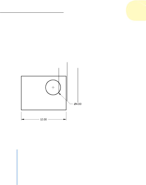
In this section, we discuss how to set those factors that control the format and appearance of dimensions, but we start with a brief anatomy lesson. AutoCAD uses the names shown in Figure 14-3 and described in the following list to refer to the parts of each dimension:
Dimension line
Arrowhead Dimension text
|
|
|
|
|
|
|
|
|
|
|
|
|
|
|
|
|
|
|
|
|
Extension line |
Dimension text |
|
|
|||
|
|
|
|
|
|
|
|
|
Dimension line |
Arrowhead |
|||
Figure 14-3: The parts of a dimension.
Dimension text: The numeric value that indicates the true distance or angle between points or lines. Dimension text can also include other information in addition to or instead of the number. For example, you can add a suffix, such as TYP., to indicate that a dimension is typical of several similar configurations; you can add manufacturing tolerances; and you can show dual dimensioning in alternate units.
Dimension lines: In linear dimensions, the dimension lines indicate the true distance between points. Angular dimensions have curved dimension lines with the center of the curve at the vertex point of the objects being dimensioned. For radius and diameter dimensions, the dimension
www.it-ebooks.info
308 Part III: If Drawings Could Talk
line simply points at or through the center of the object being dimensioned.(See Figure 14-2 for examples of these dimension types.)
Arrowheads: The dimension’s arrowheads appear at the end or ends of the dimension lines and emphasize the extent of the dimensioned length. AutoCAD’s default arrowhead style is the closed, filled type
shown in Figure 14-3, but you can choose other symbols, such as dots or tick marks, to indicate the ends of the dimension lines. (Don’t get “ticked off,” but AutoCAD calls the line ending an arrowhead even when, as in the case of a tick mark, it doesn’t look like an arrow.)
Extension lines: These extend outward from the definition points (also known as defpoints) that you select (usually by snapping to points on an object) to the dimension lines. By drafting convention, a small gap usually exists between the defpoints and the beginning of the extension lines. Also by convention, the extension lines usually extend just past the dimension lines — refer to Figure 14-3 for examples. AutoCAD makes
dimensions look tidier by assigning fixed gap sizes and projection lengths for the extension lines, and if you need to dimension to circles or center lines, you can assign dash-dot linetypes to either or both extension lines.
Defpoints: When you create any kind of dimension, AutoCAD places one or more definition points (universally known as defpoints) on a special layer named (what else?) Defpoints, which the program creates when a dimension command is issued for the first time. These points are usually invisible because the objects being dimensioned are on top of them, but you can see where they sit by selecting a dimension to turn on its grips. The grips on the objects being dimensioned are on the dimension’s definition points. Because you wouldn’t want these points to appear when you plot your drawings, the Defpoints layer has a special property: Nothing created on the Defpoints layer will ever print.
Because of the Defpoints layer’s nonprinting property, experienced users have been using it for years as a place to put sketches, guidelines, and important notes (for example, “Don’t forget to buy bread on the way home!”). We don’t endorse this practice because a convoluted relationship exists between the Defpoints layer and Layer0. Namely, it can be very hard to tell what’s
on which layer, and that can make the drawing harder to edit. If you want a “scratch” layer for those important notes, create one named Scratch and set it to NoPlot in the Layer Properties Manager palette. (For more about layers and the Layer Properties Manager, see Chapter 6.)
In the early days, AutoCAD controlled the appearance of dimensions by using about 20 dimensioning system variables. For example, to switch dimension text from showing decimal values to showing fractions, the setting of DIMLUNIT would be changed from 2 to 5. Similarly, DIMDEC sets the number of places of decimal, or the smallest fraction (would you believe 1/256 of an inch?). We discuss system variables in Chapter 26.
www.it-ebooks.info
Chapter 14: Entering New Dimensions 309
The problem was that every time you wanted to switch back and forth between decimals and fractions, you had to change these two variables. To set a system variable, or SysVar, you enter its name, followed by a suitable value as determined from Help. The only reason we mention this is because you’re bound to run into older drawings that were done this way.
The good news is that AutoCAD later added named dimension styles. You can now set up a decimal style, a fractional style, a style with specific manufacturing tolerances, and so on. All it takes is a couple of quick mouse clicks to switch between them.
Some people will try to warn you that AutoCAD dimensioning is a big, complicated, difficult subject. Don’t be alarmed, however. The basic principles are actually quite simple. The problem is that every industry has its own dimensioning conventions, habits, and quirks. As usual, AutoCAD tries to support them all — and, in so doing, makes things a bit cumbersome for everyone.
The good news is that you should have to adjust things to suit your specific industry or company only once, and then all dimensions will suit the specified standard. The really good news is that it usually takes only a bit of finetuning of the default settings to cover most of your dimensioning needs.
Dimension styles are saved within the current drawing. The really, really good news is that you can save this drawing as a template file (we cover templates in Chapter 4) so that all new drawings created from this template will have the dimension styles predefined. The really, really, really good news is that you’re working in an office where someone has already set up suitable dimension styles. If this is the case, you can skim over the next section a little more quickly.
You add dimensions to a drawing after you’ve drawn at least some of the geometry; otherwise, you won’t have much to dimension! (Well, duh.) Your dimensioning and overall drafting efficiency improve if you add dimensions in batches rather than draw a line, place a dimension, draw another line, place another dimension. . . .
Creating and managing dimension styles
A dimension style (or DimStyle for short) is a collection of drawing settings called dimension variables (or DimVars for short), which are a special class of the system variables that we describe in Chapter 26.
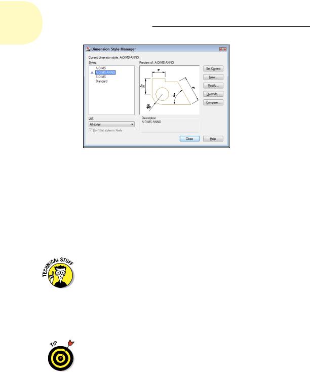
If you do need to create your own dimension styles or you want to tweak existing ones, use the DIMSTYLE command. You can invoke it by clicking the small diagonal arrow in the lower-right corner of the Dimensions panel of the Annotate tab of the Ribbon. This brings up the Dimension Style Manager dialog box, as shown in Figure 14-4.
www.it-ebooks.info
310 Part III: If Drawings Could Talk
Figure 14-4: Yet another manager, this one for dimension styles.
Every drawing comes with a default dimension style named Standard (for imperial [feet-and-inches] drawings) or ISO-25 (for metric drawings) and a matching Annotative style. We cover Annotative dimensions later in this chapter. Although you can use and modify the Standard or ISO-25 style, we suggest that you leave them as-is and create your own dimension style(s) for the settings that are appropriate to your work. This approach ensures that you can use the default style as a reference. More important, it avoids a
potential naming conflict that can change the way your dimensions look if the current drawing gets inserted into another drawing. (Chapter 17 describes this potential conflict.)
When you install AutoCAD, it checks with Windows to see what country was selected when Windows was installed, and then sets its measurement system accordingly. If you’re in the United States or one of the few other (backward) countries that still use imperial units, the default dimension style is Standard; most of the rest of the world defaults to ISO-25. Canada, on the other hand, is nominally metric, but most people still use imperial. The system variable MEASUREINIT controls the default action. If set to 0 (zero), AutoCAD uses imperial units; if set to 1, metric units are used. Among other things, this setting also affects text styles (see Chapter 13), hatching (see Chapter 15), and noncontinuous line types (see Chapters 4 and 6).
Starting a new drawing from an ISO template (for example, acadiso.dwt) forces everything to metric, and starting a new drawing from a non-ISO template (for example, acad.dwt) forces everything to imperial, regardless of the setting of MEASUREINIT.
www.it-ebooks.info