- •About the Authors
- •Dedication
- •Authors’ Acknowledgments
- •Table of Contents
- •Introduction
- •What’s Not (And What Is) in This Book
- •Mac attack!
- •Who Do We Think You Are?
- •How This Book Is Organized
- •Part I: AutoCAD 101
- •Part II: Let There Be Lines
- •Part III: If Drawings Could Talk
- •Part IV: Advancing with AutoCAD
- •Part V: On a 3D Spree
- •Part VI: The Part of Tens
- •But wait . . . there’s more!
- •Icons Used in This Book
- •A Few Conventions — Just in Case
- •Commanding from the keyboard
- •Tying things up with the Ribbon
- •Where to Go from Here
- •Why AutoCAD?
- •The Importance of Being DWG
- •Seeing the LT
- •Checking System Requirements
- •Suddenly, It’s 2013!
- •AutoCAD Does Windows (And Office)
- •And They’re Off: AutoCAD’s Opening Screens
- •Running with Ribbons
- •Getting with the Program
- •Looking for Mr. Status Bar
- •Let your fingers do the talking: The command window
- •The key(board) to AutoCAD success
- •Keeping tabs on palettes
- •Down the main stretch: The drawing area
- •Fun with F1
- •A Simple Setup
- •Drawing a (Base) Plate
- •Drawing rectangles on the right layers
- •Circling your plate
- •Nuts to you
- •Getting a Closer Look with Zoom and Pan
- •Modifying to Make It Merrier
- •Hip-hip-array!
- •Stretching out
- •Crossing your hatches
- •Following the Plot
- •A Setup Roadmap
- •Choosing your units
- •Weighing up your scales
- •Thinking annotatively
- •Thinking about paper
- •Defending your border
- •A Template for Success
- •Making the Most of Model Space
- •Setting your units
- •Making the drawing area snap-py (and grid-dy)
- •Setting linetype and dimension scales
- •Entering drawing properties
- •Making Templates Your Own
- •Setting Up a Layout in Paper Space
- •Will that be tabs or buttons?
- •View layouts Quick(View)ly
- •Creating a layout
- •Copying and changing layouts
- •Lost in paper space
- •Spaced out
- •A view(port) for drawing in
- •About Paper Space Layouts and Plotting
- •Managing Your Properties
- •Layer one on me!
- •Accumulating properties
- •Creating new layers
- •Manipulating layers
- •Using Named Objects
- •Using AutoCAD DesignCenter
- •Copying layers between drawings
- •Controlling Your Precision
- •Keyboard capers: Coordinate input
- •Understanding AutoCAD’s coordinate systems
- •Grab an object and make it snappy
- •Other Practical Precision Procedures
- •Introducing the AutoCAD Drawing Commands
- •The Straight and Narrow: Lines, Polylines, and Polygons
- •Toeing the line
- •Connecting the lines with polyline
- •Squaring off with rectangles
- •Choosing your sides with polygon
- •(Throwing) Curves
- •Going full circle
- •Arc-y-ology
- •Solar ellipses
- •Splines: The sketchy, sinuous curves
- •Donuts: The circles with a difference
- •Revision clouds on the horizon
- •Scoring Points
- •Commanding and Selecting
- •Command-first editing
- •Selection-first editing
- •Direct object manipulation
- •Choosing an editing style
- •Grab It
- •One-by-one selection
- •Selection boxes left and right
- •Perfecting Selecting
- •AutoCAD Groupies
- •Object Selection: Now You See It . . .
- •Get a Grip
- •About grips
- •A gripping example
- •Move it!
- •Copy, or a kinder, gentler Move
- •A warm-up stretch
- •Your AutoCAD Toolkit
- •The Big Three: Move, Copy, and Stretch
- •Base points and displacements
- •Move
- •Copy
- •Copy between drawings
- •Stretch
- •More Manipulations
- •Mirror
- •Rotate
- •Scale
- •Array
- •Offset
- •Slicing, Dicing, and Splicing
- •Trim and Extend
- •Break
- •Fillet and Chamfer and Blend
- •Join
- •When Editing Goes Bad
- •Zoom and Pan with Glass and Hand
- •The wheel deal
- •Navigating your drawing
- •Controlling your cube
- •Time to zoom
- •A View by Any Other Name . . .
- •Looking Around in Layout Land
- •Degenerating and Regenerating
- •Getting Ready to Write
- •Simply stylish text
- •Taking your text to new heights
- •One line or two?
- •Your text will be justified
- •Using the Same Old Line
- •Turning On Your Annotative Objects
- •Saying More in Multiline Text
- •Making it with Mtext
- •It slices; it dices . . .
- •Doing a number on your Mtext lists
- •Line up in columns — now!
- •Modifying Mtext
- •Gather Round the Tables
- •Tables have style, too
- •Creating and editing tables
- •Take Me to Your Leader
- •Electing a leader
- •Multi options for multileaders
- •How Do You Measure Up?
- •A Field Guide to Dimensions
- •The lazy drafter jumps over to the quick dimension commands
- •Dimension associativity
- •Where, oh where, do my dimensions go?
- •The Latest Styles in Dimensioning
- •Creating and managing dimension styles
- •Let’s get stylish!
- •Adjusting style settings
- •Size Matters
- •Details at other scales
- •Editing Dimensions
- •Editing dimension geometry
- •Editing dimension text
- •Controlling and editing dimension associativity
- •Batten Down the Hatches!
- •Don’t Count Your Hatches. . .
- •Size Matters!
- •We can do this the hard way. . .
- •. . . or we can do this the easy way
- •Annotative versus non-annotative
- •Pushing the Boundary (Of) Hatch
- •Your hatching has no style!
- •Hatch from scratch
- •Editing Hatch Objects
- •You Say Printing, We Say Plotting
- •The Plot Quickens
- •Plotting success in 16 steps
- •Get with the system
- •Configure it out
- •Preview one, two
- •Instead of fit, scale it
- •Plotting the Layout of the Land
- •Plotting Lineweights and Colors
- •Plotting with style
- •Plotting through thick and thin
- •Plotting in color
- •It’s a (Page) Setup!
- •Continuing the Plot Dialog
- •The Plot Sickens
- •Rocking with Blocks
- •Creating Block Definitions
- •Inserting Blocks
- •Attributes: Fill-in-the-Blank Blocks
- •Creating attribute definitions
- •Defining blocks that contain attribute definitions
- •Inserting blocks that contain attribute definitions
- •Edit attribute values
- •Extracting data
- •Exploding Blocks
- •Purging Unused Block Definitions
- •Arraying Associatively
- •Comparing the old and new ARRAY commands
- •Hip, hip, array!
- •Associatively editing
- •Going External
- •Becoming attached to your xrefs
- •Layer-palooza
- •Creating and editing an external reference file
- •Forging an xref path
- •Managing xrefs
- •Blocks, Xrefs, and Drawing Organization
- •Mastering the Raster
- •Attaching a raster image
- •Maintaining your image
- •Theme and Variations: Dynamic Blocks
- •Lights! Parameters!! Actions!!!
- •Manipulating dynamic blocks
- •Maintaining Design Intent
- •Defining terms
- •Forget about drawing with precision!
- •Constrain yourself
- •Understanding Geometric Constraints
- •Applying a little more constraint
- •AutoConstrain yourself!
- •Understanding Dimensional Constraints
- •Practice a little constraint
- •Making your drawing even smarter
- •Using the Parameters Manager
- •Dimensions or constraints — have it both ways!
- •The Internet and AutoCAD: An Overview
- •You send me
- •Send it with eTransmit
- •Rapid eTransmit
- •Bad reception?
- •Help from the Reference Manager
- •Design Web Format — Not Just for the Web
- •All about DWF and DWFx
- •Autodesk Design Review 2013
- •The Drawing Protection Racket
- •Autodesk Weather Forecast: Increasing Cloud
- •Working Solidly in the Cloud
- •Free AutoCAD!
- •Going once, going twice, going 123D
- •Your head planted firmly in the cloud
- •The pros
- •The cons
- •Cloudy with a shower of DWGs
- •AutoCAD 2013 cloud connectivity
- •Tomorrow’s Forecast
- •Understanding 3D Digital Models
- •Tools of the Trade
- •Warp speed ahead
- •Entering the third dimension
- •Untying the Ribbon and opening some palettes
- •Modeling from Above
- •Using 3D coordinate input
- •Using point filters
- •Object snaps and object snap tracking
- •Changing Planes
- •Displaying the UCS icon
- •Adjusting the UCS
- •Navigating the 3D Waters
- •Orbit à go-go
- •Taking a spin around the cube
- •Grabbing the SteeringWheels
- •Visualizing 3D Objects
- •Getting Your 3D Bearings
- •Creating a better 3D template
- •Seeing the world from new viewpoints
- •From Drawing to Modeling in 3D
- •Drawing basic 3D objects
- •Gaining a solid foundation
- •Drawing solid primitives
- •Adding the Third Dimension to 2D Objects
- •Creating 3D objects from 2D drawings
- •Modifying 3D Objects
- •Selecting subobjects
- •Working with gizmos
- •More 3D variants of 2D commands
- •Editing solids
- •Get the 2D Out of Here!
- •A different point of view
- •But wait! There’s more!
- •But wait! There’s less!
- •Do You See What I See?
- •Visualizing the Digital World
- •Adding Lighting
- •Default lighting
- •User-defined lights
- •Sunlight
- •Creating and Applying Materials
- •Defining a Background
- •Rendering a 3D Model
- •Autodesk Feedback Community
- •Autodesk Discussion Groups
- •Autodesk’s Own Bloggers
- •Autodesk University
- •The Autodesk Channel on YouTube
- •The World Wide (CAD) Web
- •Your Local ATC
- •Your Local User Group
- •AUGI
- •Books
- •Price
- •3D Abilities
- •Customization Options
- •Network Licensing
- •Express Tools
- •Parametrics
- •Standards Checking
- •Data Extraction
- •MLINE versus DLINE
- •Profiles
- •Reference Manager
- •And The Good News Is . . .
- •APERTURE
- •DIMASSOC
- •MENUBAR
- •MIRRTEXT
- •OSNAPZ
- •PICKBOX
- •REMEMBERFOLDERS
- •ROLLOVERTIPS
- •TOOLTIPS
- •VISRETAIN
- •And the Bonus Round
- •Index
Chapter 10: Get a Grip on Object Selection 205
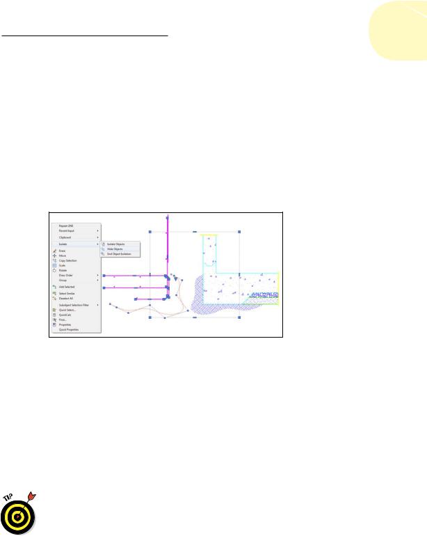
and you see the Isolate item shown in Figure 10-7. A status bar icon — a light bulb at the lower-right corner of the display — is dimmed when objects are either hidden or isolated. Click this icon to open a menu that lets you turn off the hiding or isolating.
If you’re worried about the possible implications of this (“Hmm. . . I was sure I added those center lines . . . do I need to add them again?”), relax. Hiding and isolating objects is temporary — it only lasts as long as your current drawing session. If you end a drawing with objects isolated or hidden, they reappear when you reopen the file.
Rumor has it that the Autodesk programmers stole this cloaking and uncloaking concept from the Romulans.
Figure 10-7: Make those selected objects go away (but only temporarily!).
Get a Grip
Although command-first editing is the most flexible and widespread editing style in AutoCAD, it’s not the only way. Grip editing is a useful adjunct to command-first editing, especially when you want to modify just one or two objects. You may have encountered grip editing when using other kinds of graphics programs. But even if you’re an experienced user of other graphics programs, you’ve never seen grips used in quite the way that AutoCAD uses them.
Anything that you can do with grip editing can be done with command-first editing as well. In some situations, grip editing is a little more efficient or convenient than command-first editing, but command-first editing always gets the job done. If you master only one style of editing, make it command-first style. In other words, feel free to skip this section — at least until you’re comfortable with command-first editing.
www.it-ebooks.info
206 Part II: Let There Be Lines
About grips
Grips are those little square, rectangular, or triangular handles that appear on an object after you select it.
In their simplest guise, AutoCAD grips work similarly to the little squares on graphical objects in other Windows programs. But in AutoCAD, instead of clicking and dragging a grip, you must click, release the mouse button, move the crosshairs, and click again at the new location. (By separating the selection of beginning and ending points into two different operations, AutoCAD allows you to use different techniques — such as different object snaps — to select each point.)
AutoCAD grips are, for sophisticated users, better than the grips found in most other programs because you can do so much more with them. You can, for example, use AutoCAD grips to move, stretch, or copy an object. You also can use them to rotate an object, scale it to a different size, or mirror an object — that is, create one or more reversed copies. Grips also act as visible object snaps, or little magnets that attract the crosshairs.
Starting with AutoCAD 2012, grips on lines, arcs, and elliptical arcs have become multifunctional. Hovering over an endpoint grip displays a pop-up menu that offers you a choice of lengthening or stretching the object. Hovering over the midpoint grip on an arc offers the choice of stretching the arc by its midpoint (that is, keeping the same endpoints) or changing its radius. Elliptical arcs display triangular grips that let you increase the length of the arc without changing its other parameters. Hovering over a grip on the midpoint of a polyline segment offers the choice of stretching (that is, moving
the current segment while maintaining its connections to its siblings), adding a new vertex (that is, split the current segment into two), or turning a line segment into an arc or vice versa.
A gripping example
The following sections cover in detail the five grip editing modes: STRETCH, MOVE, ROTATE, SCALE, and MIRROR. Follow these steps to explore the grip editing modes:
1.Draw some simple geometry, such as the object shown in Figure 10-8.
Here’s a great place to practice some of the straight-line object creation tools we describe in Chapter 8!
2.Press Esc to make sure that no command is active and no objects are selected, and then click Quick Properties on the status bar to turn off the Quick Properties palette.
www.it-ebooks.info
Chapter 10: Get a Grip on Object Selection 207
The Quick Properties palette is pretty useful for editing the properties of objects, but more often than not, it gets in the way when you want to edit the objects themselves. Besides, properties should normally be set ByLayer rather than by object overrides. Property overrides are covered in Chapter 6.
AutoCAD displays a blank command prompt — that is, no command is currently active.
3.Click an object onscreen to select it and display its grips.
Grips — solid blue squares on the selected object — appear at various points on the object. Note that the AutoCAD command prompt remains blank; you haven’t started a command or grip editing operation yet.
4.Click another object.
Both the newly selected object and the previously selected object display grips.
5.Click one of the grips on either object.
If a pop-up menu appears when you get close to a grip, ignore it for now and go ahead and click the grip. The blue square turns to a red square. This grip is now hot, or selected and ready for a grip editing operation.
Grip editing options now appear on the command line. The first option to appear is STRETCH.
6.Press the spacebar repeatedly to cycle through the five grip editing options on the command line.
** STRETCH **
Specify stretch point or [Base point/Copy/Undo/eXit]: ** MOVE **
Specify move point or [Base point/Copy/Undo/eXit]: ** ROTATE **
Specify rotation angle or [Base point/Copy/Undo/Reference/eXit]: ** SCALE **
Specify scale factor or [Base point/Copy/Undo/Reference/eXit]: ** MIRROR **
Specify second point or [Base point/Copy/Undo/eXit]:
The grip editing option displayed on the command line and the Dynamic Input tooltip (if Dynamic Input is enabled) changes as you press the spacebar. If you move the crosshairs (without picking) in between each press of the spacebar, the appearance of your selected object changes as you display each option. Choosing STRETCH, for example, causes a stretched version of the object to appear onscreen.
Pressing the spacebar a bunch of times is a good way to become familiar with the grip editing modes, but there’s a more direct way to choose
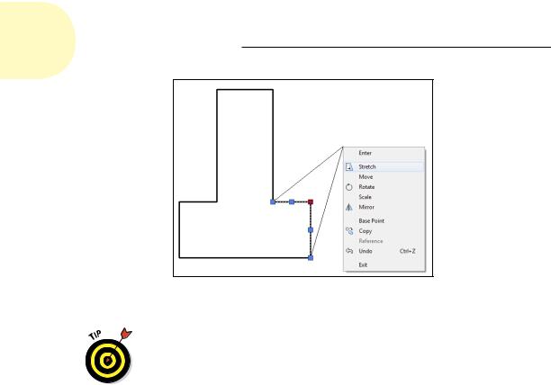
a particular mode. After you click a grip to make it hot, right-click to display the grip editing menu. That menu contains all the grip editing options plus some other choices, as shown in Figure 10-8.
www.it-ebooks.info
208 Part II: Let There Be Lines
Figure 10-8: The grip editiwng right-click menu.
If Dynamic Input is enabled, pressing the down-arrow key while cycling through the grip editing options displays a dynamic menu at the crosshairs from which you can choose options specific to the current grip editing function.
7.Press the spacebar until STRETCH (or the option you want) reappears as the grip editing option.
8.Move the hot grip in the direction in which you want to stretch (or otherwise manipulate) your object.
AutoCAD dynamically updates the image of the object to show you what the modified object will look like before you click the final location.
9.Click again to finish the grip editing operation.
The selected object with the hot grip updates.
10.Click the same grip that you chose in Step 5 (now in a different location) to make it hot.
11.This time, move the crosshairs near one of the grips on the other object. When you see the magnetic pull of the grip on the other object, click again to connect the hot grip with the other grip.
The object point represented by the hot grip now coincides exactly with the grip on the other object.
12.Press Esc to deselect all objects and remove all grips.
Figure 10-9 shows a hot (red) endpoint grip of a line being connected to the endpoint grip of another line. The angled line shows the original position of the line being edited, and the thin vertical line shows the new position. Using
www.it-ebooks.info