- •About the Authors
- •Dedication
- •Authors’ Acknowledgments
- •Table of Contents
- •Introduction
- •What’s Not (And What Is) in This Book
- •Mac attack!
- •Who Do We Think You Are?
- •How This Book Is Organized
- •Part I: AutoCAD 101
- •Part II: Let There Be Lines
- •Part III: If Drawings Could Talk
- •Part IV: Advancing with AutoCAD
- •Part V: On a 3D Spree
- •Part VI: The Part of Tens
- •But wait . . . there’s more!
- •Icons Used in This Book
- •A Few Conventions — Just in Case
- •Commanding from the keyboard
- •Tying things up with the Ribbon
- •Where to Go from Here
- •Why AutoCAD?
- •The Importance of Being DWG
- •Seeing the LT
- •Checking System Requirements
- •Suddenly, It’s 2013!
- •AutoCAD Does Windows (And Office)
- •And They’re Off: AutoCAD’s Opening Screens
- •Running with Ribbons
- •Getting with the Program
- •Looking for Mr. Status Bar
- •Let your fingers do the talking: The command window
- •The key(board) to AutoCAD success
- •Keeping tabs on palettes
- •Down the main stretch: The drawing area
- •Fun with F1
- •A Simple Setup
- •Drawing a (Base) Plate
- •Drawing rectangles on the right layers
- •Circling your plate
- •Nuts to you
- •Getting a Closer Look with Zoom and Pan
- •Modifying to Make It Merrier
- •Hip-hip-array!
- •Stretching out
- •Crossing your hatches
- •Following the Plot
- •A Setup Roadmap
- •Choosing your units
- •Weighing up your scales
- •Thinking annotatively
- •Thinking about paper
- •Defending your border
- •A Template for Success
- •Making the Most of Model Space
- •Setting your units
- •Making the drawing area snap-py (and grid-dy)
- •Setting linetype and dimension scales
- •Entering drawing properties
- •Making Templates Your Own
- •Setting Up a Layout in Paper Space
- •Will that be tabs or buttons?
- •View layouts Quick(View)ly
- •Creating a layout
- •Copying and changing layouts
- •Lost in paper space
- •Spaced out
- •A view(port) for drawing in
- •About Paper Space Layouts and Plotting
- •Managing Your Properties
- •Layer one on me!
- •Accumulating properties
- •Creating new layers
- •Manipulating layers
- •Using Named Objects
- •Using AutoCAD DesignCenter
- •Copying layers between drawings
- •Controlling Your Precision
- •Keyboard capers: Coordinate input
- •Understanding AutoCAD’s coordinate systems
- •Grab an object and make it snappy
- •Other Practical Precision Procedures
- •Introducing the AutoCAD Drawing Commands
- •The Straight and Narrow: Lines, Polylines, and Polygons
- •Toeing the line
- •Connecting the lines with polyline
- •Squaring off with rectangles
- •Choosing your sides with polygon
- •(Throwing) Curves
- •Going full circle
- •Arc-y-ology
- •Solar ellipses
- •Splines: The sketchy, sinuous curves
- •Donuts: The circles with a difference
- •Revision clouds on the horizon
- •Scoring Points
- •Commanding and Selecting
- •Command-first editing
- •Selection-first editing
- •Direct object manipulation
- •Choosing an editing style
- •Grab It
- •One-by-one selection
- •Selection boxes left and right
- •Perfecting Selecting
- •AutoCAD Groupies
- •Object Selection: Now You See It . . .
- •Get a Grip
- •About grips
- •A gripping example
- •Move it!
- •Copy, or a kinder, gentler Move
- •A warm-up stretch
- •Your AutoCAD Toolkit
- •The Big Three: Move, Copy, and Stretch
- •Base points and displacements
- •Move
- •Copy
- •Copy between drawings
- •Stretch
- •More Manipulations
- •Mirror
- •Rotate
- •Scale
- •Array
- •Offset
- •Slicing, Dicing, and Splicing
- •Trim and Extend
- •Break
- •Fillet and Chamfer and Blend
- •Join
- •When Editing Goes Bad
- •Zoom and Pan with Glass and Hand
- •The wheel deal
- •Navigating your drawing
- •Controlling your cube
- •Time to zoom
- •A View by Any Other Name . . .
- •Looking Around in Layout Land
- •Degenerating and Regenerating
- •Getting Ready to Write
- •Simply stylish text
- •Taking your text to new heights
- •One line or two?
- •Your text will be justified
- •Using the Same Old Line
- •Turning On Your Annotative Objects
- •Saying More in Multiline Text
- •Making it with Mtext
- •It slices; it dices . . .
- •Doing a number on your Mtext lists
- •Line up in columns — now!
- •Modifying Mtext
- •Gather Round the Tables
- •Tables have style, too
- •Creating and editing tables
- •Take Me to Your Leader
- •Electing a leader
- •Multi options for multileaders
- •How Do You Measure Up?
- •A Field Guide to Dimensions
- •The lazy drafter jumps over to the quick dimension commands
- •Dimension associativity
- •Where, oh where, do my dimensions go?
- •The Latest Styles in Dimensioning
- •Creating and managing dimension styles
- •Let’s get stylish!
- •Adjusting style settings
- •Size Matters
- •Details at other scales
- •Editing Dimensions
- •Editing dimension geometry
- •Editing dimension text
- •Controlling and editing dimension associativity
- •Batten Down the Hatches!
- •Don’t Count Your Hatches. . .
- •Size Matters!
- •We can do this the hard way. . .
- •. . . or we can do this the easy way
- •Annotative versus non-annotative
- •Pushing the Boundary (Of) Hatch
- •Your hatching has no style!
- •Hatch from scratch
- •Editing Hatch Objects
- •You Say Printing, We Say Plotting
- •The Plot Quickens
- •Plotting success in 16 steps
- •Get with the system
- •Configure it out
- •Preview one, two
- •Instead of fit, scale it
- •Plotting the Layout of the Land
- •Plotting Lineweights and Colors
- •Plotting with style
- •Plotting through thick and thin
- •Plotting in color
- •It’s a (Page) Setup!
- •Continuing the Plot Dialog
- •The Plot Sickens
- •Rocking with Blocks
- •Creating Block Definitions
- •Inserting Blocks
- •Attributes: Fill-in-the-Blank Blocks
- •Creating attribute definitions
- •Defining blocks that contain attribute definitions
- •Inserting blocks that contain attribute definitions
- •Edit attribute values
- •Extracting data
- •Exploding Blocks
- •Purging Unused Block Definitions
- •Arraying Associatively
- •Comparing the old and new ARRAY commands
- •Hip, hip, array!
- •Associatively editing
- •Going External
- •Becoming attached to your xrefs
- •Layer-palooza
- •Creating and editing an external reference file
- •Forging an xref path
- •Managing xrefs
- •Blocks, Xrefs, and Drawing Organization
- •Mastering the Raster
- •Attaching a raster image
- •Maintaining your image
- •Theme and Variations: Dynamic Blocks
- •Lights! Parameters!! Actions!!!
- •Manipulating dynamic blocks
- •Maintaining Design Intent
- •Defining terms
- •Forget about drawing with precision!
- •Constrain yourself
- •Understanding Geometric Constraints
- •Applying a little more constraint
- •AutoConstrain yourself!
- •Understanding Dimensional Constraints
- •Practice a little constraint
- •Making your drawing even smarter
- •Using the Parameters Manager
- •Dimensions or constraints — have it both ways!
- •The Internet and AutoCAD: An Overview
- •You send me
- •Send it with eTransmit
- •Rapid eTransmit
- •Bad reception?
- •Help from the Reference Manager
- •Design Web Format — Not Just for the Web
- •All about DWF and DWFx
- •Autodesk Design Review 2013
- •The Drawing Protection Racket
- •Autodesk Weather Forecast: Increasing Cloud
- •Working Solidly in the Cloud
- •Free AutoCAD!
- •Going once, going twice, going 123D
- •Your head planted firmly in the cloud
- •The pros
- •The cons
- •Cloudy with a shower of DWGs
- •AutoCAD 2013 cloud connectivity
- •Tomorrow’s Forecast
- •Understanding 3D Digital Models
- •Tools of the Trade
- •Warp speed ahead
- •Entering the third dimension
- •Untying the Ribbon and opening some palettes
- •Modeling from Above
- •Using 3D coordinate input
- •Using point filters
- •Object snaps and object snap tracking
- •Changing Planes
- •Displaying the UCS icon
- •Adjusting the UCS
- •Navigating the 3D Waters
- •Orbit à go-go
- •Taking a spin around the cube
- •Grabbing the SteeringWheels
- •Visualizing 3D Objects
- •Getting Your 3D Bearings
- •Creating a better 3D template
- •Seeing the world from new viewpoints
- •From Drawing to Modeling in 3D
- •Drawing basic 3D objects
- •Gaining a solid foundation
- •Drawing solid primitives
- •Adding the Third Dimension to 2D Objects
- •Creating 3D objects from 2D drawings
- •Modifying 3D Objects
- •Selecting subobjects
- •Working with gizmos
- •More 3D variants of 2D commands
- •Editing solids
- •Get the 2D Out of Here!
- •A different point of view
- •But wait! There’s more!
- •But wait! There’s less!
- •Do You See What I See?
- •Visualizing the Digital World
- •Adding Lighting
- •Default lighting
- •User-defined lights
- •Sunlight
- •Creating and Applying Materials
- •Defining a Background
- •Rendering a 3D Model
- •Autodesk Feedback Community
- •Autodesk Discussion Groups
- •Autodesk’s Own Bloggers
- •Autodesk University
- •The Autodesk Channel on YouTube
- •The World Wide (CAD) Web
- •Your Local ATC
- •Your Local User Group
- •AUGI
- •Books
- •Price
- •3D Abilities
- •Customization Options
- •Network Licensing
- •Express Tools
- •Parametrics
- •Standards Checking
- •Data Extraction
- •MLINE versus DLINE
- •Profiles
- •Reference Manager
- •And The Good News Is . . .
- •APERTURE
- •DIMASSOC
- •MENUBAR
- •MIRRTEXT
- •OSNAPZ
- •PICKBOX
- •REMEMBERFOLDERS
- •ROLLOVERTIPS
- •TOOLTIPS
- •VISRETAIN
- •And the Bonus Round
- •Index
174 Part II: Let There Be Lines
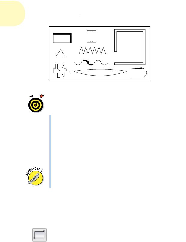
Figure 8-5: A plethora of polylines.
The LINE and PLINE commands work well for drawing a series of end-to-end single lines, but what if you want to draw a series of double lines to represent, for example, the edges of a wall or roadway? Here are some options:
Use the AutoCAD MLINE command to draw multilines — series of two or more parallel straight lines. The AutoCAD multiline feature was full of limitations when it debuted way back in 1994 (in the notorious
Release 13), and despite some minor tweaks in AutoCAD 2006, it hasn’t improved significantly since then. It exists mostly for compatibility with MicroStation files. Look up the MLINE and MLSTYLE commands in AutoCAD’s online help system if you’d like to tangle with this feature, but be prepared to spend time experimenting and struggling.
Use the PLINE command to draw a single set of connected line and/or arc segments, and then use the OFFSET command to create one or more sets of parallel segments. Chapter 11 covers the OFFSET command.
In AutoCAD LT only, use the DLINE (DL), or Double Line, command to draw pairs of parallel line and/or arc segments. AutoCAD LT doesn’t include the MLINE command, which, given MLINE’s problems, is more of a blessing than a limitation. AutoCAD, on the other hand, doesn’t include the DLINE command. (Score one for the little brother!)
Squaring off with rectangles
You can use the PLINE or LINE command to draw a rectangle, segment by segment. In most cases, though, you’ll find it easier to use the specialpurpose RECTANG command. The following procedure demonstrates how:
1.Set an appropriate layer to be current.
2.Click the Rectangle button on the Home tab’s Draw panel, or type REC and press Enter.
www.it-ebooks.info
Chapter 8: Along the Straight and Narrow 175
AutoCAD starts the RECTANG command and prompts you to specify a point for one corner of the rectangle. The command line shows
Specify first corner point or [Chamfer/Elevation/ Fillet/Thickness/Width]:
You can add fancy effects with the additional command options. The default options work best for most purposes. Look up RECTANG in the AutoCAD help system if you want to know more about the options.
3. Specify the first corner by clicking a point or typing coordinates.
AutoCAD prompts you to specify the other corner of the rectangle — the one that’s diagonally opposite from the first corner.
Specify other corner point or [Area/Dimensions/
Rotation]:
4. Specify the other corner by clicking a point or typing coordinates.
If you know the size of the rectangle that you want to draw (for example, 100 units long by 75 units high), type relative coordinates to specify the dimensions — for example, @100,75, or just 100,75 if Dynamic Input is enabled. (Chapter 7 describes how to type coordinates.)
AutoCAD draws the rectangle.
Unlike the neglected MLINE command, the RECTANG command has improved considerably since its debut. You can specify a rotation angle and — very handy for space planners — you can provide one dimension and an area. RECTANG will calculate the length of the other side and draw the rectangle.
Choosing your sides with polygon
Rectangles and other closed polylines are types of polygons, or closed figures with three or more sides. The AutoCAD POLYGON command provides a quick way of drawing regular polygons — polygons in which all sides and angles are equal. This is different from an escaped parrot.
The following procedure demonstrates the POLYGON command:
1.Set an appropriate layer to be current.
2.Click Polygon on the Home tab’s Draw panel’s Rectangle drop-down button, or type POL and press Enter.
AutoCAD starts the POLYGON command and prompts you to enter the number of sides for the polygon.
Enter number of sides <4>:
3.Type the number of sides for the polygon that you want to draw and press Enter.
Your polygon can have between 3 and 1,024 sides.
www.it-ebooks.info
176 Part II: Let There Be Lines
AutoCAD prompts you to specify the center point of the polygon.
Specify center of polygon or [Edge]:
You can use the Edge option to draw a polygon by specifying the length of one side instead of the center and then the radius of an imaginary inscribed or circumscribed circle. The imaginary circle method is much more common.
4. Specify the center point by clicking a point or typing coordinates.
AutoCAD prompts you to specify whether the polygon will be inscribed in (that is, the corners touch the circumference of the circle) or circumscribed about (that is, the sides are tangent to the circle) an imaginary circle whose radius you will specify in Step 6. Note that circumscribed has nothing to do with being Jewish.
Enter an option [Inscribed in circle/Circumscribed about circle] <I>:
5. Type I (for inscribed) or C (for circumscribed), and press Enter.
The command line prompts you to specify the radius of an imaginary circle.
Specify radius of circle:
6.Specify the radius by typing a distance or clicking a point.
AutoCAD draws the polygon.
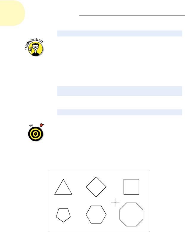
If you type a distance or you click a point with ortho turned on, the polygon will be aligned orthogonally, as shown in Figure 8-6.
Rectangles and polygons aren’t special object types. They are simply regular polylines that have been constructed by special command macros.
Figure 8-6 shows the results of drawing plenty of polygons — a practice known as polygony, which, as far as we know, is legal nearly everywhere.
Figure 8-6: A polygonal part.
www.it-ebooks.info
9
Dangerous Curves Ahead
In This Chapter
Rounding the curves with circles, arcs, splines, and clouds
Eccentric ellipses
Dunking for donuts
Making your points
Although straight-line segments predominate in many CAD drawings, even the most humdrum, rectilinear design is likely to have a few
curves. And if you’re drawing Audi car bodies or Gaudí buildings, your drawings are going to contain a lot of curves! Your drawings should also have a point; in fact, they may have several points, so at the end of this chapter, we fill you in on creating point objects in AutoCAD. But to begin, we show
you how to use the following AutoCAD curve-drawing commands:
CIRCLE: Draws circles. (You were expecting hyperbolic paraboloids, maybe?)
ARC: Draws circular arcs — arcs with center points and fixed radii, not arcs cut from ellipses, parabolas, or some other complex curve.
ELLIPSE: Draws ellipses and elliptical arcs.
SPLINE: Draws smoothly flowing curves of a variety of shapes.
DONUT: Draws filled-in rings and circles. Unfortunately, the filling isn’t jelly.
REVCLOUD: Draws freeform “clouds,” the most common application of which is to indicate revised areas in the drawing.
www.it-ebooks.info