- •About the Authors
- •Dedication
- •Authors’ Acknowledgments
- •Table of Contents
- •Introduction
- •What’s Not (And What Is) in This Book
- •Mac attack!
- •Who Do We Think You Are?
- •How This Book Is Organized
- •Part I: AutoCAD 101
- •Part II: Let There Be Lines
- •Part III: If Drawings Could Talk
- •Part IV: Advancing with AutoCAD
- •Part V: On a 3D Spree
- •Part VI: The Part of Tens
- •But wait . . . there’s more!
- •Icons Used in This Book
- •A Few Conventions — Just in Case
- •Commanding from the keyboard
- •Tying things up with the Ribbon
- •Where to Go from Here
- •Why AutoCAD?
- •The Importance of Being DWG
- •Seeing the LT
- •Checking System Requirements
- •Suddenly, It’s 2013!
- •AutoCAD Does Windows (And Office)
- •And They’re Off: AutoCAD’s Opening Screens
- •Running with Ribbons
- •Getting with the Program
- •Looking for Mr. Status Bar
- •Let your fingers do the talking: The command window
- •The key(board) to AutoCAD success
- •Keeping tabs on palettes
- •Down the main stretch: The drawing area
- •Fun with F1
- •A Simple Setup
- •Drawing a (Base) Plate
- •Drawing rectangles on the right layers
- •Circling your plate
- •Nuts to you
- •Getting a Closer Look with Zoom and Pan
- •Modifying to Make It Merrier
- •Hip-hip-array!
- •Stretching out
- •Crossing your hatches
- •Following the Plot
- •A Setup Roadmap
- •Choosing your units
- •Weighing up your scales
- •Thinking annotatively
- •Thinking about paper
- •Defending your border
- •A Template for Success
- •Making the Most of Model Space
- •Setting your units
- •Making the drawing area snap-py (and grid-dy)
- •Setting linetype and dimension scales
- •Entering drawing properties
- •Making Templates Your Own
- •Setting Up a Layout in Paper Space
- •Will that be tabs or buttons?
- •View layouts Quick(View)ly
- •Creating a layout
- •Copying and changing layouts
- •Lost in paper space
- •Spaced out
- •A view(port) for drawing in
- •About Paper Space Layouts and Plotting
- •Managing Your Properties
- •Layer one on me!
- •Accumulating properties
- •Creating new layers
- •Manipulating layers
- •Using Named Objects
- •Using AutoCAD DesignCenter
- •Copying layers between drawings
- •Controlling Your Precision
- •Keyboard capers: Coordinate input
- •Understanding AutoCAD’s coordinate systems
- •Grab an object and make it snappy
- •Other Practical Precision Procedures
- •Introducing the AutoCAD Drawing Commands
- •The Straight and Narrow: Lines, Polylines, and Polygons
- •Toeing the line
- •Connecting the lines with polyline
- •Squaring off with rectangles
- •Choosing your sides with polygon
- •(Throwing) Curves
- •Going full circle
- •Arc-y-ology
- •Solar ellipses
- •Splines: The sketchy, sinuous curves
- •Donuts: The circles with a difference
- •Revision clouds on the horizon
- •Scoring Points
- •Commanding and Selecting
- •Command-first editing
- •Selection-first editing
- •Direct object manipulation
- •Choosing an editing style
- •Grab It
- •One-by-one selection
- •Selection boxes left and right
- •Perfecting Selecting
- •AutoCAD Groupies
- •Object Selection: Now You See It . . .
- •Get a Grip
- •About grips
- •A gripping example
- •Move it!
- •Copy, or a kinder, gentler Move
- •A warm-up stretch
- •Your AutoCAD Toolkit
- •The Big Three: Move, Copy, and Stretch
- •Base points and displacements
- •Move
- •Copy
- •Copy between drawings
- •Stretch
- •More Manipulations
- •Mirror
- •Rotate
- •Scale
- •Array
- •Offset
- •Slicing, Dicing, and Splicing
- •Trim and Extend
- •Break
- •Fillet and Chamfer and Blend
- •Join
- •When Editing Goes Bad
- •Zoom and Pan with Glass and Hand
- •The wheel deal
- •Navigating your drawing
- •Controlling your cube
- •Time to zoom
- •A View by Any Other Name . . .
- •Looking Around in Layout Land
- •Degenerating and Regenerating
- •Getting Ready to Write
- •Simply stylish text
- •Taking your text to new heights
- •One line or two?
- •Your text will be justified
- •Using the Same Old Line
- •Turning On Your Annotative Objects
- •Saying More in Multiline Text
- •Making it with Mtext
- •It slices; it dices . . .
- •Doing a number on your Mtext lists
- •Line up in columns — now!
- •Modifying Mtext
- •Gather Round the Tables
- •Tables have style, too
- •Creating and editing tables
- •Take Me to Your Leader
- •Electing a leader
- •Multi options for multileaders
- •How Do You Measure Up?
- •A Field Guide to Dimensions
- •The lazy drafter jumps over to the quick dimension commands
- •Dimension associativity
- •Where, oh where, do my dimensions go?
- •The Latest Styles in Dimensioning
- •Creating and managing dimension styles
- •Let’s get stylish!
- •Adjusting style settings
- •Size Matters
- •Details at other scales
- •Editing Dimensions
- •Editing dimension geometry
- •Editing dimension text
- •Controlling and editing dimension associativity
- •Batten Down the Hatches!
- •Don’t Count Your Hatches. . .
- •Size Matters!
- •We can do this the hard way. . .
- •. . . or we can do this the easy way
- •Annotative versus non-annotative
- •Pushing the Boundary (Of) Hatch
- •Your hatching has no style!
- •Hatch from scratch
- •Editing Hatch Objects
- •You Say Printing, We Say Plotting
- •The Plot Quickens
- •Plotting success in 16 steps
- •Get with the system
- •Configure it out
- •Preview one, two
- •Instead of fit, scale it
- •Plotting the Layout of the Land
- •Plotting Lineweights and Colors
- •Plotting with style
- •Plotting through thick and thin
- •Plotting in color
- •It’s a (Page) Setup!
- •Continuing the Plot Dialog
- •The Plot Sickens
- •Rocking with Blocks
- •Creating Block Definitions
- •Inserting Blocks
- •Attributes: Fill-in-the-Blank Blocks
- •Creating attribute definitions
- •Defining blocks that contain attribute definitions
- •Inserting blocks that contain attribute definitions
- •Edit attribute values
- •Extracting data
- •Exploding Blocks
- •Purging Unused Block Definitions
- •Arraying Associatively
- •Comparing the old and new ARRAY commands
- •Hip, hip, array!
- •Associatively editing
- •Going External
- •Becoming attached to your xrefs
- •Layer-palooza
- •Creating and editing an external reference file
- •Forging an xref path
- •Managing xrefs
- •Blocks, Xrefs, and Drawing Organization
- •Mastering the Raster
- •Attaching a raster image
- •Maintaining your image
- •Theme and Variations: Dynamic Blocks
- •Lights! Parameters!! Actions!!!
- •Manipulating dynamic blocks
- •Maintaining Design Intent
- •Defining terms
- •Forget about drawing with precision!
- •Constrain yourself
- •Understanding Geometric Constraints
- •Applying a little more constraint
- •AutoConstrain yourself!
- •Understanding Dimensional Constraints
- •Practice a little constraint
- •Making your drawing even smarter
- •Using the Parameters Manager
- •Dimensions or constraints — have it both ways!
- •The Internet and AutoCAD: An Overview
- •You send me
- •Send it with eTransmit
- •Rapid eTransmit
- •Bad reception?
- •Help from the Reference Manager
- •Design Web Format — Not Just for the Web
- •All about DWF and DWFx
- •Autodesk Design Review 2013
- •The Drawing Protection Racket
- •Autodesk Weather Forecast: Increasing Cloud
- •Working Solidly in the Cloud
- •Free AutoCAD!
- •Going once, going twice, going 123D
- •Your head planted firmly in the cloud
- •The pros
- •The cons
- •Cloudy with a shower of DWGs
- •AutoCAD 2013 cloud connectivity
- •Tomorrow’s Forecast
- •Understanding 3D Digital Models
- •Tools of the Trade
- •Warp speed ahead
- •Entering the third dimension
- •Untying the Ribbon and opening some palettes
- •Modeling from Above
- •Using 3D coordinate input
- •Using point filters
- •Object snaps and object snap tracking
- •Changing Planes
- •Displaying the UCS icon
- •Adjusting the UCS
- •Navigating the 3D Waters
- •Orbit à go-go
- •Taking a spin around the cube
- •Grabbing the SteeringWheels
- •Visualizing 3D Objects
- •Getting Your 3D Bearings
- •Creating a better 3D template
- •Seeing the world from new viewpoints
- •From Drawing to Modeling in 3D
- •Drawing basic 3D objects
- •Gaining a solid foundation
- •Drawing solid primitives
- •Adding the Third Dimension to 2D Objects
- •Creating 3D objects from 2D drawings
- •Modifying 3D Objects
- •Selecting subobjects
- •Working with gizmos
- •More 3D variants of 2D commands
- •Editing solids
- •Get the 2D Out of Here!
- •A different point of view
- •But wait! There’s more!
- •But wait! There’s less!
- •Do You See What I See?
- •Visualizing the Digital World
- •Adding Lighting
- •Default lighting
- •User-defined lights
- •Sunlight
- •Creating and Applying Materials
- •Defining a Background
- •Rendering a 3D Model
- •Autodesk Feedback Community
- •Autodesk Discussion Groups
- •Autodesk’s Own Bloggers
- •Autodesk University
- •The Autodesk Channel on YouTube
- •The World Wide (CAD) Web
- •Your Local ATC
- •Your Local User Group
- •AUGI
- •Books
- •Price
- •3D Abilities
- •Customization Options
- •Network Licensing
- •Express Tools
- •Parametrics
- •Standards Checking
- •Data Extraction
- •MLINE versus DLINE
- •Profiles
- •Reference Manager
- •And The Good News Is . . .
- •APERTURE
- •DIMASSOC
- •MENUBAR
- •MIRRTEXT
- •OSNAPZ
- •PICKBOX
- •REMEMBERFOLDERS
- •ROLLOVERTIPS
- •TOOLTIPS
- •VISRETAIN
- •And the Bonus Round
- •Index
Chapter 4: Setup for Success 105
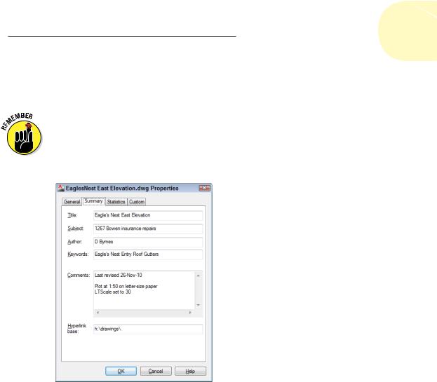
the Drawing Utilities section, choose Drawing Properties to open the Drawing Properties dialog box; then click the Summary tab. Enter the drawing scale and the drawing scale factor you’re using in the Comments area, plus any other information you think useful.
Don’t confuse drawing properties (which are really file properties) with your drawing’s object properties — they’re different things. The properties you enter here can help you or someone you love when she opens your drawing and wonders how you set it up. Object properties are a big enough topic to merit their own chapter — see Chapter 6.
Figure 4-7: Surveying your drawing’s properties.
Making Templates Your Own
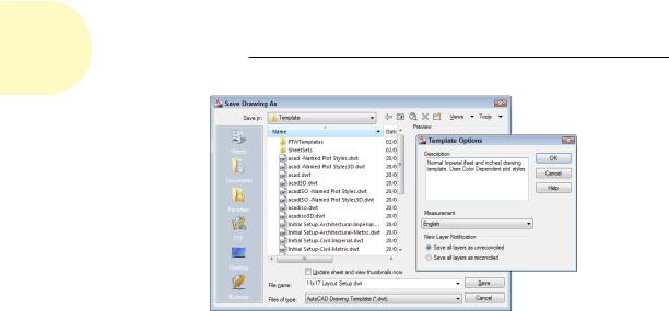
You can create a template from any DWG file by using the Save Drawing As dialog box. Follow these steps to save your drawing as a template:
1.Click Save As on the Quick Access Toolbar.
The Save Drawing As dialog box appears, as shown in Figure 4-8.
2.From the Files of Type drop-down list, choose AutoCAD Drawing Template (*.dwt) or AutoCAD LT Drawing Template (*.dwt).
3.Navigate to the folder where you want to store the drawing template.
www.it-ebooks.info
106 Part I: AutoCAD 101
Figure 4-8: Saving a drawing as a template and applying options.
The AutoCAD 2013 default folder for drawing templates is buried deep in the bowels of your Windows user profile, which by default isn’t visible in Windows Explorer. Hey, we never said this made any sense! Save your templates there if you want them to appear in AutoCAD’s Select Template list. You can save your templates in another folder, but if you want to use them later, you have to navigate to that folder every time you want to use them. See the Technical Stuff paragraph that follows this procedure for additional suggestions.
4.Enter a name for the drawing template in the File Name text box and click Save.
A dialog box for the template description and units appears.
5.Specify the template’s measurement units (English or Metric) in the drop-down list.
Enter the key info now — you can’t do it later unless you save the template to a different name. Don’t bother filling in the Description field; AutoCAD doesn’t display it in the Select Template dialog box. Don’t worry about the New Layer Notification area shown in Figure 4-8 for now; we tell you all about drawing layers in Chapter 6.
6.Click OK to save the file.
The Template Options dialog box closes, and the template is saved to your hard drive.
7.To save your drawing as a regular drawing, click Save As on the Quick Access Toolbar.
The Save Drawing As dialog box appears again.
8.From the Files of Type drop-down list, choose AutoCAD 2013 Drawing (*.dwg).
www.it-ebooks.info
Chapter 4: Setup for Success 107
Choose the AutoCAD LT equivalent, if that’s your version. AutoCAD 2013 uses a new file format that can’t be opened by earlier releases. Choose a previous DWG file format if you want to be able to open your drawing in AutoCAD 2012 or earlier, but note that some features introduced in later releases may not translate properly to earlier ones, and probably won’t survive a round trip back into 2013.
9.Navigate to the folder where you want to store the drawing.
Use a different folder from the one with your template drawings.
10.Enter the name of the drawing in the File Name text box and click Save.
The file is saved. Now, when you save it in the future, the regular file — not the template file — is updated.
The QNEW (Quick NEW) command, when properly configured, can bypass the Select Template dialog box and create a new drawing from your favorite template. The first button on the Quick Access Toolbar — the button with the plain white sheet of paper — runs the newer QNEW command instead of the older NEW command.
To put the Quick into QNEW, though, you have to tell AutoCAD which default template to use:
1.Click the Application button, and then click the Options button at the lower-right corner of the Application Menu.
2.On the Files tab, choose Template Settings Default Template File
Name for QNEW.
The QNEW default file name setting is None, which causes QNEW to act just like NEW (that is, QNEW opens the Select Template dialog box). Specify the name of your favorite template here, and you get a new drawing file based on it every time you click QNEW.
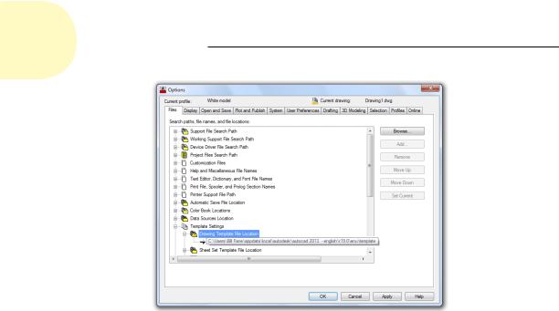
AutoCAD 2013 stores drawing templates and many other support files under your Windows user folder. To discover where your template folder is hiding, open the Options dialog box. On the Files tab, choose Template Settings Drawing Template File Location, as shown in Figure 4-9.
You don’t have to keep your template files where that bossy Mister Gates tells you. Create a folder that you can find easily (for example, C:\Acad-
templates or F:\Acad-custom\templates on a network drive), put the templates that you actually use there, and change the Drawing Template File Location setting so that it points to your new template folder.
www.it-ebooks.info
108 Part I: AutoCAD 101
Figure 4-9: Seek and you shall find your template folder.
www.it-ebooks.info
5
Planning for Paper
In This Chapter
Setting up paper space layouts
Buttons or tabs for layout fashionistas
Looking into viewports
Working in paper space
Most of what the earlier chapters look at revolves around setting up the model space environment — that infinitely large, three-dimensional
realm wherein you create your gleaming towers, your wondrous electronic gadgetry, . . . or your garden shed or your angle bracket. However, you may have picked up a hint here or there that AutoCAD has a whole different environment known as paper space.
The final product of all this setup, remember, is a printed drawing on a piece of paper. In most industries, paper drawings are legal contract documents, so it’s pretty important that they’re understandable and easily
read. The first part of that process is configuring the sheet layout in paper space, which we explain in this chapter. For the actual process of outputting either model space or layouts to printer or plotter, see Chapter 16.
Chapter 2 introduces you to the two spaces — model and paper — and Chapter 4 explains how to configure model space for efficient drawing. Before you plunge into paper space, a quick recap of model space is in order.
Model space is the drawing environment that’s current when the
Model tab (not the Model button) on the status bar is active. Model space is where you create the “real” objects that you’re drawing, so these objects are referred to as model geometry whether they’re 2D or 3D entities. When the Model tab is active, you see objects in model space only — anything in paper space is invisible.
www.it-ebooks.info