

- •About the Authors
- •Dedication
- •Authors’ Acknowledgments
- •Table of Contents
- •Introduction
- •What’s Not (And What Is) in This Book
- •Mac attack!
- •Who Do We Think You Are?
- •How This Book Is Organized
- •Part I: AutoCAD 101
- •Part II: Let There Be Lines
- •Part III: If Drawings Could Talk
- •Part IV: Advancing with AutoCAD
- •Part V: On a 3D Spree
- •Part VI: The Part of Tens
- •But wait . . . there’s more!
- •Icons Used in This Book
- •A Few Conventions — Just in Case
- •Commanding from the keyboard
- •Tying things up with the Ribbon
- •Where to Go from Here
- •Why AutoCAD?
- •The Importance of Being DWG
- •Seeing the LT
- •Checking System Requirements
- •Suddenly, It’s 2013!
- •AutoCAD Does Windows (And Office)
- •And They’re Off: AutoCAD’s Opening Screens
- •Running with Ribbons
- •Getting with the Program
- •Looking for Mr. Status Bar
- •Let your fingers do the talking: The command window
- •The key(board) to AutoCAD success
- •Keeping tabs on palettes
- •Down the main stretch: The drawing area
- •Fun with F1
- •A Simple Setup
- •Drawing a (Base) Plate
- •Drawing rectangles on the right layers
- •Circling your plate
- •Nuts to you
- •Getting a Closer Look with Zoom and Pan
- •Modifying to Make It Merrier
- •Hip-hip-array!
- •Stretching out
- •Crossing your hatches
- •Following the Plot
- •A Setup Roadmap
- •Choosing your units
- •Weighing up your scales
- •Thinking annotatively
- •Thinking about paper
- •Defending your border
- •A Template for Success
- •Making the Most of Model Space
- •Setting your units
- •Making the drawing area snap-py (and grid-dy)
- •Setting linetype and dimension scales
- •Entering drawing properties
- •Making Templates Your Own
- •Setting Up a Layout in Paper Space
- •Will that be tabs or buttons?
- •View layouts Quick(View)ly
- •Creating a layout
- •Copying and changing layouts
- •Lost in paper space
- •Spaced out
- •A view(port) for drawing in
- •About Paper Space Layouts and Plotting
- •Managing Your Properties
- •Layer one on me!
- •Accumulating properties
- •Creating new layers
- •Manipulating layers
- •Using Named Objects
- •Using AutoCAD DesignCenter
- •Copying layers between drawings
- •Controlling Your Precision
- •Keyboard capers: Coordinate input
- •Understanding AutoCAD’s coordinate systems
- •Grab an object and make it snappy
- •Other Practical Precision Procedures
- •Introducing the AutoCAD Drawing Commands
- •The Straight and Narrow: Lines, Polylines, and Polygons
- •Toeing the line
- •Connecting the lines with polyline
- •Squaring off with rectangles
- •Choosing your sides with polygon
- •(Throwing) Curves
- •Going full circle
- •Arc-y-ology
- •Solar ellipses
- •Splines: The sketchy, sinuous curves
- •Donuts: The circles with a difference
- •Revision clouds on the horizon
- •Scoring Points
- •Commanding and Selecting
- •Command-first editing
- •Selection-first editing
- •Direct object manipulation
- •Choosing an editing style
- •Grab It
- •One-by-one selection
- •Selection boxes left and right
- •Perfecting Selecting
- •AutoCAD Groupies
- •Object Selection: Now You See It . . .
- •Get a Grip
- •About grips
- •A gripping example
- •Move it!
- •Copy, or a kinder, gentler Move
- •A warm-up stretch
- •Your AutoCAD Toolkit
- •The Big Three: Move, Copy, and Stretch
- •Base points and displacements
- •Move
- •Copy
- •Copy between drawings
- •Stretch
- •More Manipulations
- •Mirror
- •Rotate
- •Scale
- •Array
- •Offset
- •Slicing, Dicing, and Splicing
- •Trim and Extend
- •Break
- •Fillet and Chamfer and Blend
- •Join
- •When Editing Goes Bad
- •Zoom and Pan with Glass and Hand
- •The wheel deal
- •Navigating your drawing
- •Controlling your cube
- •Time to zoom
- •A View by Any Other Name . . .
- •Looking Around in Layout Land
- •Degenerating and Regenerating
- •Getting Ready to Write
- •Simply stylish text
- •Taking your text to new heights
- •One line or two?
- •Your text will be justified
- •Using the Same Old Line
- •Turning On Your Annotative Objects
- •Saying More in Multiline Text
- •Making it with Mtext
- •It slices; it dices . . .
- •Doing a number on your Mtext lists
- •Line up in columns — now!
- •Modifying Mtext
- •Gather Round the Tables
- •Tables have style, too
- •Creating and editing tables
- •Take Me to Your Leader
- •Electing a leader
- •Multi options for multileaders
- •How Do You Measure Up?
- •A Field Guide to Dimensions
- •The lazy drafter jumps over to the quick dimension commands
- •Dimension associativity
- •Where, oh where, do my dimensions go?
- •The Latest Styles in Dimensioning
- •Creating and managing dimension styles
- •Let’s get stylish!
- •Adjusting style settings
- •Size Matters
- •Details at other scales
- •Editing Dimensions
- •Editing dimension geometry
- •Editing dimension text
- •Controlling and editing dimension associativity
- •Batten Down the Hatches!
- •Don’t Count Your Hatches. . .
- •Size Matters!
- •We can do this the hard way. . .
- •. . . or we can do this the easy way
- •Annotative versus non-annotative
- •Pushing the Boundary (Of) Hatch
- •Your hatching has no style!
- •Hatch from scratch
- •Editing Hatch Objects
- •You Say Printing, We Say Plotting
- •The Plot Quickens
- •Plotting success in 16 steps
- •Get with the system
- •Configure it out
- •Preview one, two
- •Instead of fit, scale it
- •Plotting the Layout of the Land
- •Plotting Lineweights and Colors
- •Plotting with style
- •Plotting through thick and thin
- •Plotting in color
- •It’s a (Page) Setup!
- •Continuing the Plot Dialog
- •The Plot Sickens
- •Rocking with Blocks
- •Creating Block Definitions
- •Inserting Blocks
- •Attributes: Fill-in-the-Blank Blocks
- •Creating attribute definitions
- •Defining blocks that contain attribute definitions
- •Inserting blocks that contain attribute definitions
- •Edit attribute values
- •Extracting data
- •Exploding Blocks
- •Purging Unused Block Definitions
- •Arraying Associatively
- •Comparing the old and new ARRAY commands
- •Hip, hip, array!
- •Associatively editing
- •Going External
- •Becoming attached to your xrefs
- •Layer-palooza
- •Creating and editing an external reference file
- •Forging an xref path
- •Managing xrefs
- •Blocks, Xrefs, and Drawing Organization
- •Mastering the Raster
- •Attaching a raster image
- •Maintaining your image
- •Theme and Variations: Dynamic Blocks
- •Lights! Parameters!! Actions!!!
- •Manipulating dynamic blocks
- •Maintaining Design Intent
- •Defining terms
- •Forget about drawing with precision!
- •Constrain yourself
- •Understanding Geometric Constraints
- •Applying a little more constraint
- •AutoConstrain yourself!
- •Understanding Dimensional Constraints
- •Practice a little constraint
- •Making your drawing even smarter
- •Using the Parameters Manager
- •Dimensions or constraints — have it both ways!
- •The Internet and AutoCAD: An Overview
- •You send me
- •Send it with eTransmit
- •Rapid eTransmit
- •Bad reception?
- •Help from the Reference Manager
- •Design Web Format — Not Just for the Web
- •All about DWF and DWFx
- •Autodesk Design Review 2013
- •The Drawing Protection Racket
- •Autodesk Weather Forecast: Increasing Cloud
- •Working Solidly in the Cloud
- •Free AutoCAD!
- •Going once, going twice, going 123D
- •Your head planted firmly in the cloud
- •The pros
- •The cons
- •Cloudy with a shower of DWGs
- •AutoCAD 2013 cloud connectivity
- •Tomorrow’s Forecast
- •Understanding 3D Digital Models
- •Tools of the Trade
- •Warp speed ahead
- •Entering the third dimension
- •Untying the Ribbon and opening some palettes
- •Modeling from Above
- •Using 3D coordinate input
- •Using point filters
- •Object snaps and object snap tracking
- •Changing Planes
- •Displaying the UCS icon
- •Adjusting the UCS
- •Navigating the 3D Waters
- •Orbit à go-go
- •Taking a spin around the cube
- •Grabbing the SteeringWheels
- •Visualizing 3D Objects
- •Getting Your 3D Bearings
- •Creating a better 3D template
- •Seeing the world from new viewpoints
- •From Drawing to Modeling in 3D
- •Drawing basic 3D objects
- •Gaining a solid foundation
- •Drawing solid primitives
- •Adding the Third Dimension to 2D Objects
- •Creating 3D objects from 2D drawings
- •Modifying 3D Objects
- •Selecting subobjects
- •Working with gizmos
- •More 3D variants of 2D commands
- •Editing solids
- •Get the 2D Out of Here!
- •A different point of view
- •But wait! There’s more!
- •But wait! There’s less!
- •Do You See What I See?
- •Visualizing the Digital World
- •Adding Lighting
- •Default lighting
- •User-defined lights
- •Sunlight
- •Creating and Applying Materials
- •Defining a Background
- •Rendering a 3D Model
- •Autodesk Feedback Community
- •Autodesk Discussion Groups
- •Autodesk’s Own Bloggers
- •Autodesk University
- •The Autodesk Channel on YouTube
- •The World Wide (CAD) Web
- •Your Local ATC
- •Your Local User Group
- •AUGI
- •Books
- •Price
- •3D Abilities
- •Customization Options
- •Network Licensing
- •Express Tools
- •Parametrics
- •Standards Checking
- •Data Extraction
- •MLINE versus DLINE
- •Profiles
- •Reference Manager
- •And The Good News Is . . .
- •APERTURE
- •DIMASSOC
- •MENUBAR
- •MIRRTEXT
- •OSNAPZ
- •PICKBOX
- •REMEMBERFOLDERS
- •ROLLOVERTIPS
- •TOOLTIPS
- •VISRETAIN
- •And the Bonus Round
- •Index

370 Part IV: Advancing with AutoCAD
Rocking with Blocks
A block is a collection of objects grouped to form a single object. You can insert this collection more than once in the same drawing, and when you do, all instances of the block remain identical. By redefining the block definition, you can automatically change all instances of the block insertion (officially called a “block reference”) at once. Although a block lives within a specific drawing, you can transfer copies of it into other drawings. And you can add fill-in-the-blank text fields — attributes — to blocks.
You can create single-line or multiline attributes; in addition to having more than one line, multiline attributes have many of the formatting options of multiline text. And blocks both with and without attributes can be defined as annotative objects to boot. (See Chapter 13 for a rundown on annotative objects.)
To use a block in a drawing, you need two things: a block definition and one or more block insertions. AutoCAD doesn’t always make the distinction between these two things very clear, but you need to understand the differ-
ence to avoid terminal confusion about blocks. (Maybe this syndrome should be called “blockheadedness”?)
A block definition lives in an invisible area of your drawing file: the block table. (It’s one of those sets of named symbols that we describe in Chapter 6.) The block table is like a book of graphical recipes for making different kinds of blocks. Each block definition is like a recipe for making one kind of block. When you insert a block, as described in the upcoming section, “Inserting Blocks,” AutoCAD creates a special object called a “block reference.” The block reference points to the recipe and tells AutoCAD, “Hey, draw me according to the instructions in this recipe!”
Although a block may look like a collection of objects stored together and given a name, it’s really a graphical recipe (the block definition) plus one or more pointers to that recipe (one or more block references). Each time you insert a particular block, you create another pointer to the same recipe.
The advantages of blocks include
Grouping objects when they belong together logically: You can draw a screw, using lines and arcs, and then make a block definition out of all these objects. When you insert the screw block, AutoCAD treats it as a single object for purposes of copying, moving, and so on.
Saving time and reducing errors: Inserting a block is, of course, much quicker than redrawing the same geometry again. And the less geometry you draw from scratch, the less opportunity there is to make a mistake.
www.it-ebooks.info
Chapter 17: The ABCs of Blocks 371
Efficiency of storage when you reuse the same block repeatedly: If you insert the same screw block 15 times in a drawing, AutoCAD stores the detailed block definition only once. The 15 block references that point to the block definition take up much less disk space than 15 copies of all the lines, polylines, and arcs. No matter how big the block definition is, each insertion adds only about 100 bytes to the drawing file size.
The ability to edit all instances of a symbol in a drawing simply by modifying a single block definition: If you decide that your design requires a different kind of screw, you simply redefine the screw’s block definition. With this new recipe, AutoCAD then replaces all 15 screws automatically. That’s a heck of a lot faster than erasing and recopying 15 screws!
Varying the appearance of block references by using dynamic blocks:
If your design requires a different kind of screw, you simply change the view of the screw to the other kind (assuming, of course, you’ve defined your screw as a dynamic block). Every instance of the screw in the drawing could show a different kind of screw. And that’s a heck of a lot more efficient than creating 15 different block definitions! For the lowdown on creating, inserting, and manipulating dynamic blocks, see Chapter 18.
Blocks aren’t all that great for drawing elements that might be used in multiple drawings, however, especially if several people are working on and sharing parts of drawings with one another. That’s because blocks, after they get into multiple drawings, stay in each drawing; a later modification to a block definition in one drawing does not automatically modify all the other drawings that use that block. If you use a block with your company’s logo in a number of drawings and then you decide to change the logo, you must make the change within each drawing that uses the block. Using external reference (xref) files can overcome this problem. We cover XREFs in Chapter 18.
If all you need to do is group some objects so that you can more easily select them for copying, moving, and so on, use AutoCAD’s Group feature. We describe groupies a little more fully in Chapter 10. Type GROUP (or the command alias G) and press Enter, or simply click the Group button on the Home tab’s Groups panel. Then just select some objects, and you’re done. When you’re editing drawings that contain groups, press Ctrl+Shift+A to toggle “group-ness” on or off. If you’ve toggled group-ness on, picking any object in a group selects all objects in the group. If you’ve toggled it off, picking an object selects only that object, even if it happens to be a member of a group. For more information, refer to Chapter 10 or visit the online help index.
Blocks — along with external references, DWF and PDF underlays, raster images, and DGN files — enable you to reuse your work and the work of others, giving you the potential to save tremendous amounts of time — or to cause tremendous problems if you change a file on which other people’s
www.it-ebooks.info
372 Part IV: Advancing with AutoCAD
drawings depend. Use these features when you can to save time, but do so in an organized and careful way so as to avoid problems.
How you use blocks and xrefs depends a lot on the profession and office in which you work. Some disciplines and companies use these drawing organization features heavily and in a highly organized way, but others don’t. Ask your colleagues what the local customs are and follow them.
Creating Block Definitions
To create a block definition from objects in the current drawing, use the Block Definition dialog box. (The other way to create a block definition is by inserting another drawing file into your current drawing as a block, which we explain in the next section.) The following steps show you how to create a block definition by using the Block Definition dialog box:
1.On the Ribbon’s Home tab, click the Create button on the Block panel.
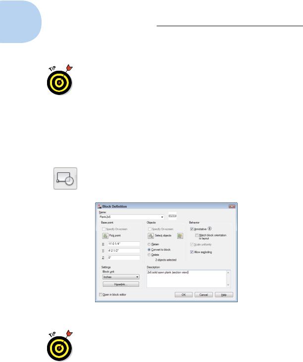
The Block Definition dialog box appears (see Figure 17-1).
Figure 17-1: The Block Definition dialog box.
Pay attention to layers when you create the objects that make up a block. As a rule, block geometry created on most layers retains the color, linetype, lineweight, transparency, and plot style properties of those layers. The exception to the rule is object geometry created on Layer 0. If you create a block by using geometry drawn on Layer 0, the block takes on the features of any layer into which you insert it.
www.it-ebooks.info
Chapter 17: The ABCs of Blocks 373
2.Type the block definition’s name in the Name text box.
If you type the name of an existing block definition, AutoCAD will warn you when you click OK at the end of the process. This isn’t always a bad
thing because AutoCAD will ask whether you want to replace that block definition with the new objects you select. This process is block redefinition. If you have a drawing with a large number of block insertions — for example, numerous bathtubs in a 1,000-room hotel — you can use a simplified block representation during the design process and then redefine it to a more complex definition just before final plot time.
To see a list of the names of all the current blocks in your drawing, open the Name drop-down list.
3.Specify the base point (also known as the insertion point) of the block, using any of the following methods:
•Enter the coordinates of the insertion point in the X, Y, and Z text boxes.
•Click the Pick Point button and then specify a point on the screen.
(In this case, use an object snap or other precision technique, as described in Chapter 7, to grab a specific point on one of the block’s objects.)
The base point is the point on the block by which you insert it later, as we describe in the next section.
Use an obvious and consistent point on the group of objects for the base point, such as the lower-left corner, so that you know what to expect when you insert the block.
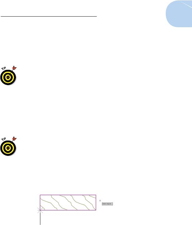
4.Click the Select Objects button and then select the objects that you want as part of the block.
AutoCAD uses the selected objects to create a block definition and displays an icon showing those objects next to the block name. Figure 17-2 shows the base point and group of selected objects during the process of creating a new block definition.
Base point
Figure 17-2: Building a block.
www.it-ebooks.info
374 Part IV: Advancing with AutoCAD
5.In the Objects area, select one of the radio buttons to tell AutoCAD what to do with the objects used to define the block: Retain them in place, convert them into a block instance, or delete them.
The default choice, Convert to Block, is usually the best. See Step 9 for a description of what happens with each choice.
6.Specify the insert units to which the block will be scaled in the Block Unit drop-down list.
When you or someone else drags the block from one drawing into another via the DesignCenter palette (see Chapter 6) or Tool Palettes (described later in this chapter), the units you specify here and the units of the drawing you’re dragging into will control the default insertion scale factor. The list contains 17 different units from Angstroms to Parsecs, but unfortunately doesn’t include fathoms or furlongs.
Three additional features in AutoCAD’s Block Definition dialog box give you even more control over what happens to your blocks as they’re inserted:
•If the Annotative check box is selected: The block insertion will be scaled to suit the current drawing scale, and additional scales can be applied so the insertion will be scaled differently to suit other drawing scales. This would typically be applied only to symbols (such as north arrows) and not to insertions of blocks depicting actual objects (such as toilets or motors). (We explain the nuts and bolts of annotative objects in Chapter 13.)
•If the Scale Uniformly check box is selected: Blocks will be inserted with the same X, Y, or Z scale factors. (Scale Uniformly is selected automatically if Annotative is selected.)
•If the Allow Exploding check box is selected: Blocks can be exploded during or after their insertion in a drawing.
7.Enter a description for the block in the Description text area.
You don’t have to enter a description to create a block, but it’s not a bad idea. Think like a database manager and enter a useful description that will identify the block to yourself and others.
8.Make sure that the Open in Block Editor check box is deselected.
You don’t need to use the Edit Block Definition dialog box unless you’re going to add dynamic features to the block. (See Chapter 18 to find out more about dynamic blocks.)
9.Click OK to complete the block definition process.
AutoCAD stores the block definition in the current drawing’s block table. The radio buttons you choose from in Step 5 do the following:
www.it-ebooks.info