

- •About the Authors
- •Dedication
- •Authors’ Acknowledgments
- •Table of Contents
- •Introduction
- •What’s Not (And What Is) in This Book
- •Mac attack!
- •Who Do We Think You Are?
- •How This Book Is Organized
- •Part I: AutoCAD 101
- •Part II: Let There Be Lines
- •Part III: If Drawings Could Talk
- •Part IV: Advancing with AutoCAD
- •Part V: On a 3D Spree
- •Part VI: The Part of Tens
- •But wait . . . there’s more!
- •Icons Used in This Book
- •A Few Conventions — Just in Case
- •Commanding from the keyboard
- •Tying things up with the Ribbon
- •Where to Go from Here
- •Why AutoCAD?
- •The Importance of Being DWG
- •Seeing the LT
- •Checking System Requirements
- •Suddenly, It’s 2013!
- •AutoCAD Does Windows (And Office)
- •And They’re Off: AutoCAD’s Opening Screens
- •Running with Ribbons
- •Getting with the Program
- •Looking for Mr. Status Bar
- •Let your fingers do the talking: The command window
- •The key(board) to AutoCAD success
- •Keeping tabs on palettes
- •Down the main stretch: The drawing area
- •Fun with F1
- •A Simple Setup
- •Drawing a (Base) Plate
- •Drawing rectangles on the right layers
- •Circling your plate
- •Nuts to you
- •Getting a Closer Look with Zoom and Pan
- •Modifying to Make It Merrier
- •Hip-hip-array!
- •Stretching out
- •Crossing your hatches
- •Following the Plot
- •A Setup Roadmap
- •Choosing your units
- •Weighing up your scales
- •Thinking annotatively
- •Thinking about paper
- •Defending your border
- •A Template for Success
- •Making the Most of Model Space
- •Setting your units
- •Making the drawing area snap-py (and grid-dy)
- •Setting linetype and dimension scales
- •Entering drawing properties
- •Making Templates Your Own
- •Setting Up a Layout in Paper Space
- •Will that be tabs or buttons?
- •View layouts Quick(View)ly
- •Creating a layout
- •Copying and changing layouts
- •Lost in paper space
- •Spaced out
- •A view(port) for drawing in
- •About Paper Space Layouts and Plotting
- •Managing Your Properties
- •Layer one on me!
- •Accumulating properties
- •Creating new layers
- •Manipulating layers
- •Using Named Objects
- •Using AutoCAD DesignCenter
- •Copying layers between drawings
- •Controlling Your Precision
- •Keyboard capers: Coordinate input
- •Understanding AutoCAD’s coordinate systems
- •Grab an object and make it snappy
- •Other Practical Precision Procedures
- •Introducing the AutoCAD Drawing Commands
- •The Straight and Narrow: Lines, Polylines, and Polygons
- •Toeing the line
- •Connecting the lines with polyline
- •Squaring off with rectangles
- •Choosing your sides with polygon
- •(Throwing) Curves
- •Going full circle
- •Arc-y-ology
- •Solar ellipses
- •Splines: The sketchy, sinuous curves
- •Donuts: The circles with a difference
- •Revision clouds on the horizon
- •Scoring Points
- •Commanding and Selecting
- •Command-first editing
- •Selection-first editing
- •Direct object manipulation
- •Choosing an editing style
- •Grab It
- •One-by-one selection
- •Selection boxes left and right
- •Perfecting Selecting
- •AutoCAD Groupies
- •Object Selection: Now You See It . . .
- •Get a Grip
- •About grips
- •A gripping example
- •Move it!
- •Copy, or a kinder, gentler Move
- •A warm-up stretch
- •Your AutoCAD Toolkit
- •The Big Three: Move, Copy, and Stretch
- •Base points and displacements
- •Move
- •Copy
- •Copy between drawings
- •Stretch
- •More Manipulations
- •Mirror
- •Rotate
- •Scale
- •Array
- •Offset
- •Slicing, Dicing, and Splicing
- •Trim and Extend
- •Break
- •Fillet and Chamfer and Blend
- •Join
- •When Editing Goes Bad
- •Zoom and Pan with Glass and Hand
- •The wheel deal
- •Navigating your drawing
- •Controlling your cube
- •Time to zoom
- •A View by Any Other Name . . .
- •Looking Around in Layout Land
- •Degenerating and Regenerating
- •Getting Ready to Write
- •Simply stylish text
- •Taking your text to new heights
- •One line or two?
- •Your text will be justified
- •Using the Same Old Line
- •Turning On Your Annotative Objects
- •Saying More in Multiline Text
- •Making it with Mtext
- •It slices; it dices . . .
- •Doing a number on your Mtext lists
- •Line up in columns — now!
- •Modifying Mtext
- •Gather Round the Tables
- •Tables have style, too
- •Creating and editing tables
- •Take Me to Your Leader
- •Electing a leader
- •Multi options for multileaders
- •How Do You Measure Up?
- •A Field Guide to Dimensions
- •The lazy drafter jumps over to the quick dimension commands
- •Dimension associativity
- •Where, oh where, do my dimensions go?
- •The Latest Styles in Dimensioning
- •Creating and managing dimension styles
- •Let’s get stylish!
- •Adjusting style settings
- •Size Matters
- •Details at other scales
- •Editing Dimensions
- •Editing dimension geometry
- •Editing dimension text
- •Controlling and editing dimension associativity
- •Batten Down the Hatches!
- •Don’t Count Your Hatches. . .
- •Size Matters!
- •We can do this the hard way. . .
- •. . . or we can do this the easy way
- •Annotative versus non-annotative
- •Pushing the Boundary (Of) Hatch
- •Your hatching has no style!
- •Hatch from scratch
- •Editing Hatch Objects
- •You Say Printing, We Say Plotting
- •The Plot Quickens
- •Plotting success in 16 steps
- •Get with the system
- •Configure it out
- •Preview one, two
- •Instead of fit, scale it
- •Plotting the Layout of the Land
- •Plotting Lineweights and Colors
- •Plotting with style
- •Plotting through thick and thin
- •Plotting in color
- •It’s a (Page) Setup!
- •Continuing the Plot Dialog
- •The Plot Sickens
- •Rocking with Blocks
- •Creating Block Definitions
- •Inserting Blocks
- •Attributes: Fill-in-the-Blank Blocks
- •Creating attribute definitions
- •Defining blocks that contain attribute definitions
- •Inserting blocks that contain attribute definitions
- •Edit attribute values
- •Extracting data
- •Exploding Blocks
- •Purging Unused Block Definitions
- •Arraying Associatively
- •Comparing the old and new ARRAY commands
- •Hip, hip, array!
- •Associatively editing
- •Going External
- •Becoming attached to your xrefs
- •Layer-palooza
- •Creating and editing an external reference file
- •Forging an xref path
- •Managing xrefs
- •Blocks, Xrefs, and Drawing Organization
- •Mastering the Raster
- •Attaching a raster image
- •Maintaining your image
- •Theme and Variations: Dynamic Blocks
- •Lights! Parameters!! Actions!!!
- •Manipulating dynamic blocks
- •Maintaining Design Intent
- •Defining terms
- •Forget about drawing with precision!
- •Constrain yourself
- •Understanding Geometric Constraints
- •Applying a little more constraint
- •AutoConstrain yourself!
- •Understanding Dimensional Constraints
- •Practice a little constraint
- •Making your drawing even smarter
- •Using the Parameters Manager
- •Dimensions or constraints — have it both ways!
- •The Internet and AutoCAD: An Overview
- •You send me
- •Send it with eTransmit
- •Rapid eTransmit
- •Bad reception?
- •Help from the Reference Manager
- •Design Web Format — Not Just for the Web
- •All about DWF and DWFx
- •Autodesk Design Review 2013
- •The Drawing Protection Racket
- •Autodesk Weather Forecast: Increasing Cloud
- •Working Solidly in the Cloud
- •Free AutoCAD!
- •Going once, going twice, going 123D
- •Your head planted firmly in the cloud
- •The pros
- •The cons
- •Cloudy with a shower of DWGs
- •AutoCAD 2013 cloud connectivity
- •Tomorrow’s Forecast
- •Understanding 3D Digital Models
- •Tools of the Trade
- •Warp speed ahead
- •Entering the third dimension
- •Untying the Ribbon and opening some palettes
- •Modeling from Above
- •Using 3D coordinate input
- •Using point filters
- •Object snaps and object snap tracking
- •Changing Planes
- •Displaying the UCS icon
- •Adjusting the UCS
- •Navigating the 3D Waters
- •Orbit à go-go
- •Taking a spin around the cube
- •Grabbing the SteeringWheels
- •Visualizing 3D Objects
- •Getting Your 3D Bearings
- •Creating a better 3D template
- •Seeing the world from new viewpoints
- •From Drawing to Modeling in 3D
- •Drawing basic 3D objects
- •Gaining a solid foundation
- •Drawing solid primitives
- •Adding the Third Dimension to 2D Objects
- •Creating 3D objects from 2D drawings
- •Modifying 3D Objects
- •Selecting subobjects
- •Working with gizmos
- •More 3D variants of 2D commands
- •Editing solids
- •Get the 2D Out of Here!
- •A different point of view
- •But wait! There’s more!
- •But wait! There’s less!
- •Do You See What I See?
- •Visualizing the Digital World
- •Adding Lighting
- •Default lighting
- •User-defined lights
- •Sunlight
- •Creating and Applying Materials
- •Defining a Background
- •Rendering a 3D Model
- •Autodesk Feedback Community
- •Autodesk Discussion Groups
- •Autodesk’s Own Bloggers
- •Autodesk University
- •The Autodesk Channel on YouTube
- •The World Wide (CAD) Web
- •Your Local ATC
- •Your Local User Group
- •AUGI
- •Books
- •Price
- •3D Abilities
- •Customization Options
- •Network Licensing
- •Express Tools
- •Parametrics
- •Standards Checking
- •Data Extraction
- •MLINE versus DLINE
- •Profiles
- •Reference Manager
- •And The Good News Is . . .
- •APERTURE
- •DIMASSOC
- •MENUBAR
- •MIRRTEXT
- •OSNAPZ
- •PICKBOX
- •REMEMBERFOLDERS
- •ROLLOVERTIPS
- •TOOLTIPS
- •VISRETAIN
- •And the Bonus Round
- •Index

408 Part IV: Advancing with AutoCAD
When you want to include attributes (variable text fields) that you can fill in each time you insert a block
Blocks let you include attribute definitions; xrefs don’t. Refer to Chapter 17 for the lowdown on attributes.
Everyone in a company or workgroup should aim for consistency as to when and how they use blocks and xrefs. Check whether guidelines exist for using blocks and xrefs in your office. If so, follow them; if not, it would be a good idea to develop some guidelines.
Mastering the Raster
AutoCAD includes four more xref-like features: the ability to attach raster images, DWF files, PDF files, and DGN files to drawings. We cover DWF and PDF files in the next section and refer you to the online help if you should find some DGN files on your hands. The image feature is useful for adding a raster logo to a drawing title block or placing a photographed map or scene behind a drawing. A raster, or bitmapped, image is one that’s stored as a field of tiny dots.
AutoCAD drawings are vector files. A vector drawing is a graphic file defined by storing geometrical definitions of a bunch of objects. Typical objects include a line (defined by its two endpoints) and a circle (defined by its center point and radius). Vector-based images are typically smaller (in terms of the disk space they occupy) and more flexible than raster images, but also are less capable of displaying visually rich images, such as photographs.
Raster images often come from digital cameras or from other programs, such as Photoshop. Raster images can also come into the computer from some kind of scanner that imports a blueline print, photograph, or other image.
Whether you’re doing your own scanning or having a service bureau do it for you, you need to know that AutoCAD handles most popular image file formats, including: the Windows BMP format; the popular Web graphics formats GIF and JPEG; common print formats such as PCX, PNG, and TIFF; the less popular DIB, FLC, FLI, GP4, MIL, RLE, RST, TGA formats, and several even more obscure ones.
Three scenarios in which you could incorporate raster images in your drawing include
Small stuff: You can add logos, special symbols, and other small images that you have in raster files.
Photographs and maps: You can add photographs (such as a future building site) and maps (for example, showing the project location).
www.it-ebooks.info
Chapter 18: Everything from Arrays to Xrefs 409
Vectorization: To convert a raster image into a vector drawing by tracing lines in the raster image, you can attach the raster image in your drawing, trace the needed lines by using AutoCAD commands, and then detach the raster image. (This procedure is okay for a simple raster image; add-on software is available, from Autodesk and others, to support automatic or semiautomatic vectorization of more complex images.)
Your raster image may be distorted a bit; for example, the aspect ratio (ratio of width to height) may not be correct, but AutoCAD won’t let you change it. No problem; simply attach the raster image, make a block that contains it, and then insert the block with different X and Y scale factors. We love cheating.
Using raster images is much like using external references. The raster image isn’t stored with your drawing file, though. Instead, a reference to the raster image file is established from within your drawing, like an xref. You can clip the image and control its size, brightness, contrast, fade, and transparency. These controls fine-tune the appearance of the raster image onscreen and on a plot.
When you attach raster images, you have to make sure that you send the raster files along when you send your drawing to someone else. Raster images are simply referenced from the drawing and aren’t part of it. If you don’t send the raster image file along with the drawing, the drawing displays a rectangle containing the name of the missing file in its place. The best way to make sure that you get all the required files when sending a drawing file to someone else is to use the ETRANSMIT command, which we cover in Chapter 20.
Some raster image files that you find on the Internet may not be appropriate
AutoCAD attachments.
Attaching a raster image
Follow these steps to bring a raster image into AutoCAD:
1.If the External References palette isn’t already open, click its icon on the Palettes panel of the View tab.
Use the drop-down list on the first toolbar button to attach a drawing, an image, or a DWF, PDF, or DGN file.
2.Click Attach Image and locate the image file you want to attach.
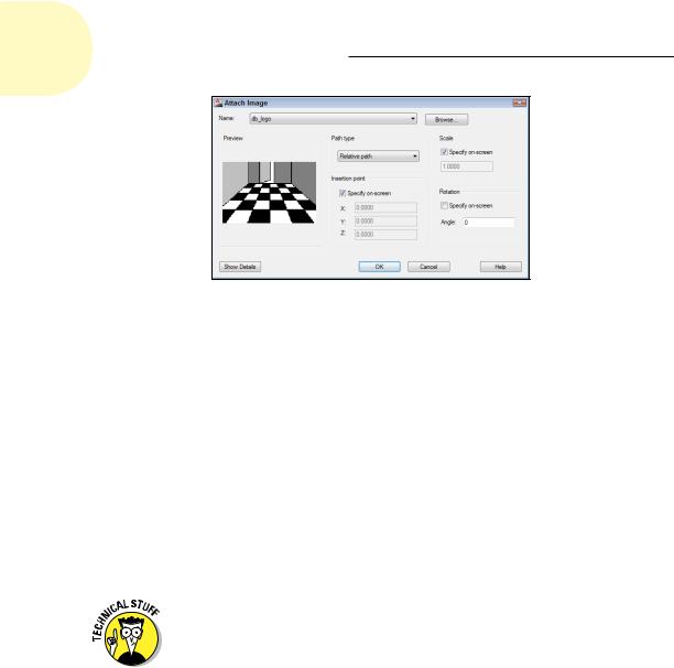
The Attach Image dialog box appears, as shown in Figure 18-6.
3.Browse to find the file you want to attach, select it, and then click Open.
The Attach Image dialog box appears.
Click the Show Details button in the Attach Image dialog box to see more information about the resolution and image size of the image you’re attaching.
www.it-ebooks.info
410 Part IV: Advancing with AutoCAD
Figure 18-6: The Attach Image dialog box.
4.Specify the parameters for the attached image in the dialog box.
Parameters include the insertion point, scale factor, and rotation angle. You can set these parameters in the dialog box or specify them onscreen, similar to what you can do with blocks and external references, as described earlier in this chapter.
The Attach Image dialog box includes the same Full Path, Relative Path, and No Path options as those for attaching xrefs. (See the “Forging an xref path” section, earlier in this chapter.)
5.Click OK.
The image appears in your drawing.
6.If you need to ensure that the raster image floats behind other objects in the drawing, select the raster image, right-click, choose Draw Order, and then choose Send to Back.
The DRAWORDER command provides additional options for which objects appear on top of which other objects. If you need this kind of flexibility, look up DRAWORDER command in the AutoCAD online help system.
Maintaining your image
You manage the images in your drawing via the External References palette. You can view a list of image files that appear in the current drawing, detach (remove) image references, and unload and reload images when needed. You can’t bind an image to your drawing, though; it always remains an external file.
You can clip images so that only part of the image is displayed in your drawing. Choose Clip from the Insert tab’s Reference panel and follow the prompts
www.it-ebooks.info
Chapter 18: Everything from Arrays to Xrefs 411
to clip the image. You can have multiple overlapping or distinct pieces of any number of images in your drawing, and only the parts you need are loaded into memory when you have your drawing open.
Raster image files often are larger than DWG files of corresponding complexity; raster file size can affect performance within AutoCAD because the raster file loads into memory when you’re working on your drawing. If you find raster attachments slowing down AutoCAD’s response, then follow these tips:
Attach raster images late in the production process.
Create a lower-resolution version of the raster file, just large enough to create the desired effect in your drawing.
Right-click an image in the External References palette and choose Unload from the menu that appears to temporarily hide an image without losing the attachment information.
In addition, raster files can also dramatically increase the time that AutoCAD takes to generate plots (and the plot file sizes). Before you settle on using large raster files in your AutoCAD drawing, do some testing on zooming, editing, and plotting.
You Say PDF, We Say DWF
The Adobe PDF format has been around for a very long time, and for a while, it seemed like Autodesk was trying to supplant it with its own universal file format — DWF (Design Web Format). That didn’t happen, but if you can’t beat them. . . . AutoCAD includes a very acceptable PDF printer driver, and both PDF and DWF are suitable candidates for external reference files.
You could think of a DWF as “DWG Lite” because it looks just like a drawing file and contains some of the actual drawing file data. We talk more about the web side of DWFs in Chapter 20; in this section, we explain how you can use DWFs as well as PDFs as reference files in your own drawings. (Some people call DWF files “dwiffs,” but we’re going to hold off on that one until we start hearing DWG files called “dwiggs”. And why is phonetic spelled that way?)
You create both DWFs and PDFs from within AutoCAD in one of two ways. Either choose Plot and select a DWF or PDF option in the Printer/Plotter name list, or choose Print Batch Plot from the Application Menu and then select DWF, DWFx, or PDF from the Publish To area of the Publish dialog box.
Both file types are compact and secure. Because you can’t edit either PDFs or DWFs in AutoCAD, both formats are ideal for two purposes:
www.it-ebooks.info

412 Part IV: Advancing with AutoCAD
You can post DWFs or PDFs on the web.
You can send your drawings to consultants and clients in a form that they can’t mess up.
You can attach PDFs or DWFs to your drawing files in pretty much the same way you attach drawings as external references. DWFs and PDFs attached to drawing files are referred to as DWF underlays or PDF underlays.
As with DWF and DGN attachments, you can object-snap to entities in the PDF underlay by enabling the Snap to Underlays function in the Reference panel slideout on the Insert tab. Setting PDF parameters is virtually identical to setting DWF parameters, and you can attach a PDF to your drawing by using exactly the same steps as the ones that follow.
The previous sections show how to attach a DWG and a raster image. Follow these steps to attach a DWF (or a PDF!) file as an underlay:
1.If the External References palette isn’t already open, click its icon on the Palettes panel of the View tab to open it.
Use the toolbar at the top of the palette to attach an external file as an xref, a raster image file, or a DGN or DWF underlay. We cover attaching xrefs and images earlier in this chapter. See the online help for information on attaching DGN files.
2.Click Attach DWF or Attach PDF and then locate the file you want to attach.
The Select Reference File dialog box appears.
3.Browse to find the file you want to attach, select it, and then click Open.
The Attach DWF Underlay or Attach PDF Underlay dialog box appears.
4.Specify the parameters for the DWF or the PDF in the dialog box.
Parameters include specifying a sheet, the insertion point, scaling factors, rotation angle, and path type (see Figure 18-7). You can set these parameters in the dialog box or specify them onscreen, just like you can do when inserting a block, attaching an xref, or attaching an image, as described earlier in this chapter.
5.Click OK.
The externally referenced DWF or PDF file appears in your drawing.
Neither PDF nor DWF files are as precise as DWGs, and that’s why they’re a lot smaller. When using object snaps to locate points in DWFs, you may see the word approximate on the Object Snap tooltip. If this is a problem, you can increase the precision of your DWF file when you create it.
www.it-ebooks.info