

110 Part I: AutoCAD 101
In AutoCAD 2013, it’s still possible to ignore paper space layouts entirely and do all your drawing and plotting in model space. But you owe it to yourself to give layouts a try. You’ll probably find that they make plotting more consistent and predictable. They’ll give you more plotting flexibility when you need it. And you’ll certainly encounter drawings from other people that make extensive use of paper space, so you need to understand it if you plan to exchange drawings with anyone else.
Setting Up a Layout in Paper Space
A paper space layout is a representation of a drawing sheet. Although the model geometry — the real stuff — goes in model space, the “not-real” drawing objects (for example, a drawing border, title block, general notes, perhaps view labels, and symbols like North arrows) all go in paper space on the layout. In essence, model space is like the world, infinitely large and three dimensional; paper space is finite — the size of a drawing sheet, in fact — and two dimensional, just like a drawing sheet.
Aside from just an arrangement of your drawing sheet, layouts also store plot information. AutoCAD can save a separate plot setting with each layout, as well as model space, so that you can plot each one differently. In practice, you’ll probably need to use only one of the paper space layout tabs, especially when you’re getting started with AutoCAD. Theory and practice are the same in theory, but seldom in practice.
Rather than just reading about it, you may also want to open a few of the AutoCAD 2013 sample drawings and click the Model and Layout buttons or tabs to witness the variety of ways in which paper space is used.
Specialized sample drawings are installed in the \Samples folder. The generic AutoCAD and AutoCAD LT sample drawings are no longer installed with the program, but they’re still available — online. Download them from www.
autodesk.com/autocad-samples or www.autodesk.com/autocadltsamples. The upside of the change is that users of either program now have access to the other’s sample files.
Will that be tabs or buttons?
The Autodesk documentation sometimes refers to the Model tab or to layout tabs, and sometimes (like just a second ago) we do here as well. In its out-of- the-box condition, AutoCAD does display actual, selectable tabs at the lowerleft edge of the drawing window, clearly labeled Model, Layout1, and Layout2 (you can see this later in the chapter in Figure 5-4). You can gain a fraction more screen space if you hide the tabs, but even when they’re hidden, they’re still referred to as tabs. Here’s how to toggle the way that tabs are displayed:
www.it-ebooks.info
Chapter 5: Planning for Paper 111
To hide layout tabs: Right-click the visible Model tab or any layout tab, and choose Hide Layout and Model Tabs from the pop-up menu.
To show layout tabs: Right-click the Model button (the one with the icon and the Model tooltip, not the Model or Paper Space button, which is sometimes confusingly labeled MODEL) — or the Layout button right next door — and choose Display Layout and Model Tabs. Huh? Rightclick the Model button but not the Model button? Correct. The one on the left end of the set of three switches between paper space or letting you reach into model space through a hole cut in the layout, while the one immediately to the right of it switches you completely over to model space.
Hiding the tabs does give you a bit more drawing area, but there’s a drawback — the Layout button can control only a single layout (whichever layout happens to be current). You have to use the Quick View Layouts feature (described in the next section) to switch between layouts, but if your drawing has only one layout, hiding the tabs is well worthwhile.
You can rename layout tabs — but not the Model tab — by double-clicking the layout name and typing a new one.
The state of your tabs is stored — but not automatically saved — in your current workspace. For example, if you’re working in the Drafting & Annotation workspace, then switch to the AutoCAD Classic workspace, and then switch back to Drafting & Annotation, the change you made from tabs to buttons (or vice versa) will not be retained. For information on saving your own custom workspace, look up workspace in the online help system.
View layouts Quick(View)ly
Quick View Layouts is the second of two features that use the Quick View image strip to display preview images of drawings or layouts. We introduce Quick View Drawings — which previews all your open drawings in the Quick View strip — in Chapter 2.
The following steps explain how to change between model space and a layout or switch between layouts:
1.Click the Quick View Layouts button on the status bar.
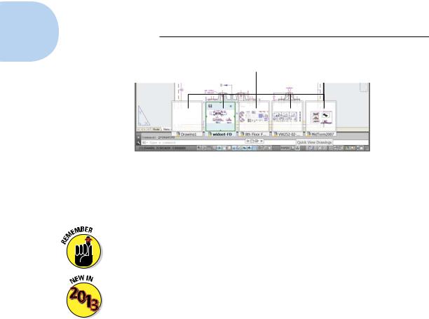
The Quick View image strip appears above the status bar and displays resizable image panels for model space and all layouts. Right below the row of images is the Quick View toolbar. Figure 5-1 shows a typical arrangement in a multilayout drawing.
www.it-ebooks.info
112 Part I: AutoCAD 101
Quick View Layouts preview images
|
|
|
|
|
|
|
|
|
|
Quick View toolbar |
|
Quick View |
||
|
|
Layouts button |
||
Model or Paper space toggle |
||||
Figure 5-1: View those layouts, and make it Quick!
Don’t confuse the Quick View toolbar with the Quick Access Toolbar that lives up top, next to the Application Menu button. (AutoCAD is getting so quick, it’s hard to keep up with it!)
AutoCAD 2013 adds an improvement. To simplify things when you have several drawings open and/or the open drawing(s) have several layouts, the Quick View panels have green borders to show which drawing and which view in that drawing are currently visible onscreen.
The Quick View toolbar contains four buttons that perform the following tasks (buttons are listed from left to right):
•Pin Quick View Layouts: Normally the images disappear as soon as you select a layout or click outside it. Clicking this button reorients the side view of the pushpin so it looks like it’s poking a hole in your screen (you should be aware that neither Autodesk nor we are responsible for punctures in your monitor) and forces the image panels to remain open.
•New Layout: Click this button to create a new layout with a single viewport. The new layout appears as a new image at the end of the strip.
•Publish: Click this button to open the Publish dialog box. You use the PUBLISH command if you have a whole set of drawings you want to output and package at one time. We explain the AutoCAD version of publishing in Chapter 20.
•Close Quick View Layouts: Use this button to close the Quick View Layouts image strip if you pinned it open. Simply clicking outside the image strip closes the image strip if it’s unpinned.
www.it-ebooks.info
Chapter 5: Planning for Paper 113
2.Move your mouse pointer over each image in the Quick View panel.
The image background highlights to indicate which layout the pointer’s focus is on.
When a panel is highlighted, two icons appear at the top corners of the panel. The Publish button at top right does the same thing as Batch Plot on the Application Menu. If you want to print the individual layout without going through all the Publish rigmarole, click the Plot icon at the top left.
3.Click the preview image of model space or the layout you want to make current.
The selected layout is activated and fills the drawing window; the preview image strip closes.
If you have a wheel mouse, you can move between previews by scrolling the wheel in either direction. You can also resize the previews by mousing over an image and then pressing the Ctrl key while scrolling the wheel back and forth.
Creating a layout
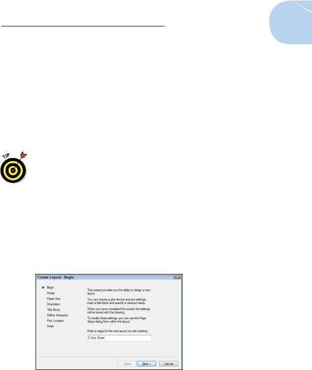
Creating a simple paper space layout is straightforward, thanks to the Create Layout Wizard, as shown in Figure 5-2. (Yes! Finally, a useful AutoCAD wizard.) The command name is LAYOUTWIZARD, but the bad news is that it’s missing in action from AutoCAD 2013’s default user interface. To get to it, type LAYOUTWIZARD at the keyboard (or, if you’re using the AutoCAD
Classic workspace, open the Insert menu and choose Layout, and then Create Layout Wizard).
Figure 5-2: The Create Layout Wizard.
www.it-ebooks.info
114 Part I: AutoCAD 101
Although the Create Layout Wizard guides you, step by step, through the process of creating a paper space layout from scratch, it doesn’t eliminate the necessity of coming up with a sensible set of layout parameters. The sheet size and plot scale that you choose provide a certain amount of space for showing your model (see the “Thinking about paper” section in Chapter 4), and wizards aren’t allowed to bend the laws of arithmetic to escape that fact. For example, a map of Australia at a scale of 1 inch = 1 foot won’t fit on an 8½- x-11-inch sheet, no way, no how. In other words, garbage in, garbage (lay) out. Fortunately, the Create Layout Wizard lends itself to experimentation, and you can easily delete layouts that don’t work.
Follow these steps to create a layout:
1.Type LAYOUTWIZARD and press Enter.
The Create Layout Wizard displays its first page and prompts you to enter a name for the new layout.
2.Give the new layout a name and click Next.
In place of the default name, Layout3, we recommend something more descriptive — for example, D-Size Sheet. Or you can call it A1-Size Sheet if you’re of the metric persuasion.
3.Choose a printer or plotter to use when plotting this layout and then click Next.
Think of your choice as the default plotter for this layout. You can change to a different plotter later — or create page setups that plot the same layout on different plotters. (We explain page setups in Chapter 16.)
Many of the names in the configured plotter list should look familiar because they’re your Windows printers (system printers, in AutoCAD lingo). Names with a .pc3 extension represent nonsystem printer drivers. See Chapter 16 for details.
4.Choose a paper size, specify whether to use inches or millimeters to represent paper units, and click Next.
The available paper sizes depend on the printer or plotter that you selected in Step 3.
5.Specify the orientation of the drawing on the paper and click Next.
The icon displaying the letter A on the piece of paper shows you which orientation is which.
6.On the Create Layout – Title Block page, select None and click Next.
We don’t recommend selecting one of the two available title blocks, as odds are slim that either of those will fit on the paper size you selected in Step 4. Here’s why . . . .
www.it-ebooks.info

Chapter 5: Planning for Paper 115
Earlier AutoCAD releases included a handy set of predrawn title blocks for a range of both imperial and metric paper sizes. Sad to say, all but two of them have disappeared, and those two are still the only ones available in AutoCAD 2013’s Layout Wizard. Unfortunately, neither of them is likely to work out for you. If, in Step 4, you chose inches as your units and any paper size other than ARCH D (36.00 x 24.00 inches) — or chose millimeters as your units and any paper size at all — the title block will not fit the sheet.
When you know your way around the program a bit, you can always draw, insert, or xref a title block later. (See Chapters 17 and 18 for information about inserting or xrefing a title block.) You can also add custom title block drawings to your AutoCAD Template folder. If you want to know where to put them, see the section on making templates in Chapter 4.
7.Define the arrangement of viewports that AutoCAD should create and select the viewport scale for them all from the drop-down list. Then click Next.
A viewport is a window from paper space into model space. You must create at least one viewport to display the model in your new layout. We tell you more about viewports in the section “A view(port) for drawing in,” later in this chapter.
The default Viewport scale, Scaled to Fit, ensures that all your model drawing objects appear in the viewport, but it results in an arbitrary scale factor. Most technical drawings require a specific scale, such as 1:100 or 1⁄8" = 1'–0".
8.Click Select Location to specify the location of the viewport(s) on the layout; then pick the viewport’s corners.
After you click the Select Location button, the Create Layout Wizard displays the preliminary layout with any title block that you’ve chosen. Pick two points to define a rectangle that falls within the drawing area of your title block (or within the plottable area of the sheet, if you chose no title block in Step 6). AutoCAD then redisplays the Finish page of the Create Layout Wizard.
AutoCAD represents the plottable area of the sheet with a dashed rectangle near the edge of the sheet. If you don’t select a location for the viewport(s), the Create Layout Wizard creates a viewport that fills the plottable area of the sheet.
9.Click Finish.
AutoCAD creates the new layout.
Like the other wizards, the Create Layout Wizard is aimed at new users or old-timers who have somehow overlooked the introduction of paper space layouts. You won’t need to run this wizard every time you start a new drawing, but you should run it once and then save the resulting file as a template for future drawings (see Chapter 4 for more about templates).
www.it-ebooks.info