

- •About the Authors
- •Dedication
- •Authors’ Acknowledgments
- •Table of Contents
- •Introduction
- •What’s Not (And What Is) in This Book
- •Mac attack!
- •Who Do We Think You Are?
- •How This Book Is Organized
- •Part I: AutoCAD 101
- •Part II: Let There Be Lines
- •Part III: If Drawings Could Talk
- •Part IV: Advancing with AutoCAD
- •Part V: On a 3D Spree
- •Part VI: The Part of Tens
- •But wait . . . there’s more!
- •Icons Used in This Book
- •A Few Conventions — Just in Case
- •Commanding from the keyboard
- •Tying things up with the Ribbon
- •Where to Go from Here
- •Why AutoCAD?
- •The Importance of Being DWG
- •Seeing the LT
- •Checking System Requirements
- •Suddenly, It’s 2013!
- •AutoCAD Does Windows (And Office)
- •And They’re Off: AutoCAD’s Opening Screens
- •Running with Ribbons
- •Getting with the Program
- •Looking for Mr. Status Bar
- •Let your fingers do the talking: The command window
- •The key(board) to AutoCAD success
- •Keeping tabs on palettes
- •Down the main stretch: The drawing area
- •Fun with F1
- •A Simple Setup
- •Drawing a (Base) Plate
- •Drawing rectangles on the right layers
- •Circling your plate
- •Nuts to you
- •Getting a Closer Look with Zoom and Pan
- •Modifying to Make It Merrier
- •Hip-hip-array!
- •Stretching out
- •Crossing your hatches
- •Following the Plot
- •A Setup Roadmap
- •Choosing your units
- •Weighing up your scales
- •Thinking annotatively
- •Thinking about paper
- •Defending your border
- •A Template for Success
- •Making the Most of Model Space
- •Setting your units
- •Making the drawing area snap-py (and grid-dy)
- •Setting linetype and dimension scales
- •Entering drawing properties
- •Making Templates Your Own
- •Setting Up a Layout in Paper Space
- •Will that be tabs or buttons?
- •View layouts Quick(View)ly
- •Creating a layout
- •Copying and changing layouts
- •Lost in paper space
- •Spaced out
- •A view(port) for drawing in
- •About Paper Space Layouts and Plotting
- •Managing Your Properties
- •Layer one on me!
- •Accumulating properties
- •Creating new layers
- •Manipulating layers
- •Using Named Objects
- •Using AutoCAD DesignCenter
- •Copying layers between drawings
- •Controlling Your Precision
- •Keyboard capers: Coordinate input
- •Understanding AutoCAD’s coordinate systems
- •Grab an object and make it snappy
- •Other Practical Precision Procedures
- •Introducing the AutoCAD Drawing Commands
- •The Straight and Narrow: Lines, Polylines, and Polygons
- •Toeing the line
- •Connecting the lines with polyline
- •Squaring off with rectangles
- •Choosing your sides with polygon
- •(Throwing) Curves
- •Going full circle
- •Arc-y-ology
- •Solar ellipses
- •Splines: The sketchy, sinuous curves
- •Donuts: The circles with a difference
- •Revision clouds on the horizon
- •Scoring Points
- •Commanding and Selecting
- •Command-first editing
- •Selection-first editing
- •Direct object manipulation
- •Choosing an editing style
- •Grab It
- •One-by-one selection
- •Selection boxes left and right
- •Perfecting Selecting
- •AutoCAD Groupies
- •Object Selection: Now You See It . . .
- •Get a Grip
- •About grips
- •A gripping example
- •Move it!
- •Copy, or a kinder, gentler Move
- •A warm-up stretch
- •Your AutoCAD Toolkit
- •The Big Three: Move, Copy, and Stretch
- •Base points and displacements
- •Move
- •Copy
- •Copy between drawings
- •Stretch
- •More Manipulations
- •Mirror
- •Rotate
- •Scale
- •Array
- •Offset
- •Slicing, Dicing, and Splicing
- •Trim and Extend
- •Break
- •Fillet and Chamfer and Blend
- •Join
- •When Editing Goes Bad
- •Zoom and Pan with Glass and Hand
- •The wheel deal
- •Navigating your drawing
- •Controlling your cube
- •Time to zoom
- •A View by Any Other Name . . .
- •Looking Around in Layout Land
- •Degenerating and Regenerating
- •Getting Ready to Write
- •Simply stylish text
- •Taking your text to new heights
- •One line or two?
- •Your text will be justified
- •Using the Same Old Line
- •Turning On Your Annotative Objects
- •Saying More in Multiline Text
- •Making it with Mtext
- •It slices; it dices . . .
- •Doing a number on your Mtext lists
- •Line up in columns — now!
- •Modifying Mtext
- •Gather Round the Tables
- •Tables have style, too
- •Creating and editing tables
- •Take Me to Your Leader
- •Electing a leader
- •Multi options for multileaders
- •How Do You Measure Up?
- •A Field Guide to Dimensions
- •The lazy drafter jumps over to the quick dimension commands
- •Dimension associativity
- •Where, oh where, do my dimensions go?
- •The Latest Styles in Dimensioning
- •Creating and managing dimension styles
- •Let’s get stylish!
- •Adjusting style settings
- •Size Matters
- •Details at other scales
- •Editing Dimensions
- •Editing dimension geometry
- •Editing dimension text
- •Controlling and editing dimension associativity
- •Batten Down the Hatches!
- •Don’t Count Your Hatches. . .
- •Size Matters!
- •We can do this the hard way. . .
- •. . . or we can do this the easy way
- •Annotative versus non-annotative
- •Pushing the Boundary (Of) Hatch
- •Your hatching has no style!
- •Hatch from scratch
- •Editing Hatch Objects
- •You Say Printing, We Say Plotting
- •The Plot Quickens
- •Plotting success in 16 steps
- •Get with the system
- •Configure it out
- •Preview one, two
- •Instead of fit, scale it
- •Plotting the Layout of the Land
- •Plotting Lineweights and Colors
- •Plotting with style
- •Plotting through thick and thin
- •Plotting in color
- •It’s a (Page) Setup!
- •Continuing the Plot Dialog
- •The Plot Sickens
- •Rocking with Blocks
- •Creating Block Definitions
- •Inserting Blocks
- •Attributes: Fill-in-the-Blank Blocks
- •Creating attribute definitions
- •Defining blocks that contain attribute definitions
- •Inserting blocks that contain attribute definitions
- •Edit attribute values
- •Extracting data
- •Exploding Blocks
- •Purging Unused Block Definitions
- •Arraying Associatively
- •Comparing the old and new ARRAY commands
- •Hip, hip, array!
- •Associatively editing
- •Going External
- •Becoming attached to your xrefs
- •Layer-palooza
- •Creating and editing an external reference file
- •Forging an xref path
- •Managing xrefs
- •Blocks, Xrefs, and Drawing Organization
- •Mastering the Raster
- •Attaching a raster image
- •Maintaining your image
- •Theme and Variations: Dynamic Blocks
- •Lights! Parameters!! Actions!!!
- •Manipulating dynamic blocks
- •Maintaining Design Intent
- •Defining terms
- •Forget about drawing with precision!
- •Constrain yourself
- •Understanding Geometric Constraints
- •Applying a little more constraint
- •AutoConstrain yourself!
- •Understanding Dimensional Constraints
- •Practice a little constraint
- •Making your drawing even smarter
- •Using the Parameters Manager
- •Dimensions or constraints — have it both ways!
- •The Internet and AutoCAD: An Overview
- •You send me
- •Send it with eTransmit
- •Rapid eTransmit
- •Bad reception?
- •Help from the Reference Manager
- •Design Web Format — Not Just for the Web
- •All about DWF and DWFx
- •Autodesk Design Review 2013
- •The Drawing Protection Racket
- •Autodesk Weather Forecast: Increasing Cloud
- •Working Solidly in the Cloud
- •Free AutoCAD!
- •Going once, going twice, going 123D
- •Your head planted firmly in the cloud
- •The pros
- •The cons
- •Cloudy with a shower of DWGs
- •AutoCAD 2013 cloud connectivity
- •Tomorrow’s Forecast
- •Understanding 3D Digital Models
- •Tools of the Trade
- •Warp speed ahead
- •Entering the third dimension
- •Untying the Ribbon and opening some palettes
- •Modeling from Above
- •Using 3D coordinate input
- •Using point filters
- •Object snaps and object snap tracking
- •Changing Planes
- •Displaying the UCS icon
- •Adjusting the UCS
- •Navigating the 3D Waters
- •Orbit à go-go
- •Taking a spin around the cube
- •Grabbing the SteeringWheels
- •Visualizing 3D Objects
- •Getting Your 3D Bearings
- •Creating a better 3D template
- •Seeing the world from new viewpoints
- •From Drawing to Modeling in 3D
- •Drawing basic 3D objects
- •Gaining a solid foundation
- •Drawing solid primitives
- •Adding the Third Dimension to 2D Objects
- •Creating 3D objects from 2D drawings
- •Modifying 3D Objects
- •Selecting subobjects
- •Working with gizmos
- •More 3D variants of 2D commands
- •Editing solids
- •Get the 2D Out of Here!
- •A different point of view
- •But wait! There’s more!
- •But wait! There’s less!
- •Do You See What I See?
- •Visualizing the Digital World
- •Adding Lighting
- •Default lighting
- •User-defined lights
- •Sunlight
- •Creating and Applying Materials
- •Defining a Background
- •Rendering a 3D Model
- •Autodesk Feedback Community
- •Autodesk Discussion Groups
- •Autodesk’s Own Bloggers
- •Autodesk University
- •The Autodesk Channel on YouTube
- •The World Wide (CAD) Web
- •Your Local ATC
- •Your Local User Group
- •AUGI
- •Books
- •Price
- •3D Abilities
- •Customization Options
- •Network Licensing
- •Express Tools
- •Parametrics
- •Standards Checking
- •Data Extraction
- •MLINE versus DLINE
- •Profiles
- •Reference Manager
- •And The Good News Is . . .
- •APERTURE
- •DIMASSOC
- •MENUBAR
- •MIRRTEXT
- •OSNAPZ
- •PICKBOX
- •REMEMBERFOLDERS
- •ROLLOVERTIPS
- •TOOLTIPS
- •VISRETAIN
- •And the Bonus Round
- •Index
516 Part V: On a 3D Spree
that can take your computer 3D model and produce a real-world object. They were originally developed with mechanical designs in mind, but architectural designers are also using them to print scale models of their buildings. More recently, the scale factor for printing buildings has become 1:1. That’s right: Full-scale concrete houses are being 3D printed straight from the computer model! At the end of the day, however, the real world still needs (or at least wants) 2D drawings.
Going the other way, or at least going even farther in the 2D world, relatively low-cost computers and powerful software make it possible for designers to produce photo-realistic images of their 3D models. Clients and customers can see the product before it’s real.
We start this chapter by showing you how to generate 2D drawings from 3D models, and then go on to discussing rendering.
Get the 2D Out of Here!
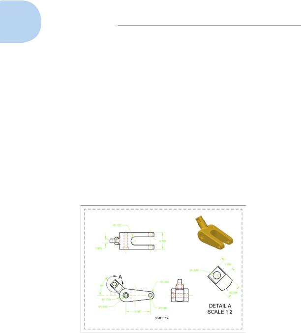
Would you believe that it took less than five minutes to produce Figure 23-1?
Figure 23-1: A drawing in less than five minutes!
Okay, we cheated a little bit. It took about an hour to produce the 3D model first, but the 2D views were produced almost instantly. The rest of the five minutes was spent adding the dimensions. The clock is running. . . .
www.it-ebooks.info
Chapter 23: On a Render Bender 517
1.Switch AutoCAD to the 3D Modeling workspace.
Select it from the drop-down list at the end of the Quick Access Toolbar in the upper-right corner of the screen.
2.Set up a 3D model.
Create a new model by using the techniques we discuss in Chapters 21 and 22, or open an existing file that contains a 3D model.
You can find the files we use in this sequence of steps at this book’s companion website. Go to www.dummies.com/go/autocad2013fd and download afd23.zip. The drawing named afd23a.dwg contains the model we use in the following steps.
3.Switch to paper space.
Click the Layout 1 tab near the lower left of the screen.
4.Delete the existing viewport by clicking the viewport object (the frame of the viewport) and then pressing Delete.
By default, new drawings created from a standard template file contain a single viewport. If you’re going to be creating new drawings like this quite a bit, we suggest that you set up a template file with the viewport already deleted. We cover templates in Chapter 4.
5.Start the VIEWBASE command.
Click the Base button from the Create View panel of the Layout tab of the Ribbon and then choose From Model Space from the drop-down list.
The VIEWBASE command creates several new layers. By default, they are the opposite of the screen color, black or white, but they always print black. You can change these layers to any color you want.
6.Position the base view.
AutoCAD automatically selects what it thinks is an appropriate scale, assuming that you’ll be placing the standard three orthographic views and one pictorial view. However, this can be changed. Select a suitable place in the lower-left quadrant of the layout sheet.
7.Define the base view.
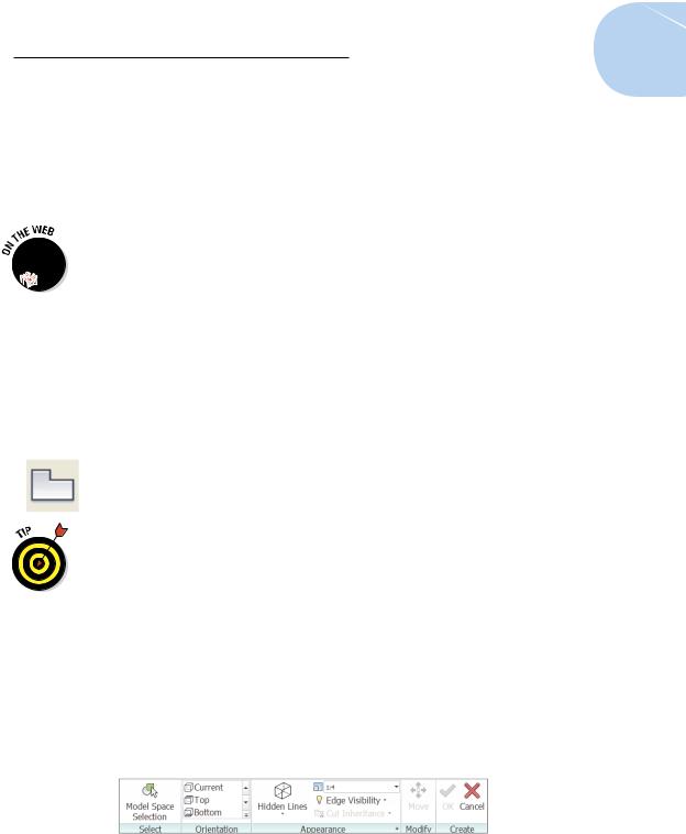
The Drawing View Creation contextual tab appears on the Ribbon as shown in Figure 23-2, a drop-down list of view options appears at your cursor, and an option list appears in the command window.
Figure 23-2: The Drawing View Creation context tab of the Ribbon.
www.it-ebooks.info
518 Part V: On a 3D Spree
Using any one of the three selection methods — Ribbon, cursor, or command window — set up the base view as follows:
•Orientation: The view shows what appears to be the bottom view of the part because AutoCAD defines top, bottom, and so on relative to the world X, Y coordinates. Select Orientation and the Top to get the view you want.
•Hidden lines: The preview image in paper space always displays in shaded mode no matter what the visual style of the model shows in model space. You want Hidden Lines to be Visible and Hidden. The view won’t change yet, but don’t worry, it will.
•Scale: This has defaulted to 1:4, which is suitable for our purposes.
•Visibility, or Edge Visibility: This specifies how to display edges that are formed where tangent surfaces meet. Normal practice is often to not display them, but this can sometimes cause features to disappear or partially disappear. If you do change this setting, we recommend that you do so from the Edge Visibility button of the Appearance panel of the Ribbon because if you hover your cursor over this button and pause for a few seconds, it produces a much more extensive tooltip list that explains each option in more detail.
•Move: Specify a new location for the view before it is finally created. This isn’t such a big deal, though, because views can always be easily moved later.
Exit (or press Enter)
Any of these view specifications can be edited later on a view-by- view basis.
Hey, what happened? The command didn’t end!
8.Place the other drawing views.
When you finish placing and defining the base view, AutoCAD automatically shifts into running the VIEWPROJ command. All you need is three quick clicks to place the top, isometric, and right-side views, and then press Enter to have AutoCAD generate the views.
9.Edit the isometric view.
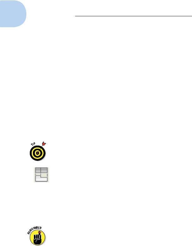
Isometric views don’t normally show hidden lines. Double-click anywhere within the isometric view to bring up the Drawing View Editor tab of the Ribbon, as shown in Figure 23-3.
Click Hidden Lines on the Appearance tab and then choose Shaded with Visible Lines from the drop-down list.
If a Ribbon button has a drop-down list, the Ribbon displays the last button that was used. There may be any one of four different buttons in this particular location.
www.it-ebooks.info
Chapter 23: On a Render Bender 519
Figure 23-3: The Drawing View Editor context tab of the Ribbon.
10.Stop the clock.
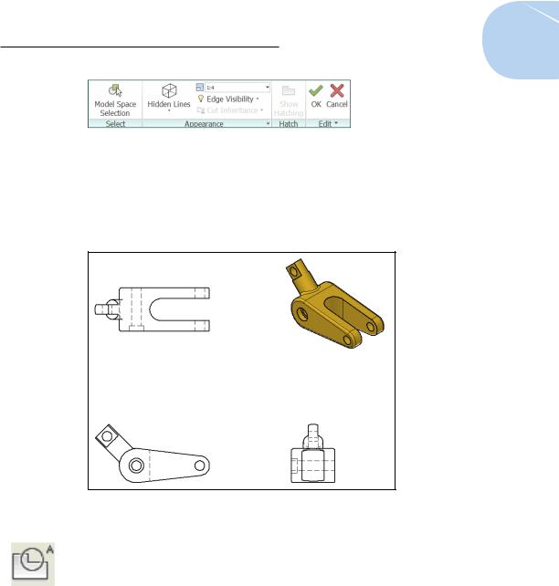
Not bad. Figure 23-4 shows three ortho views and a shaded isomeric view that were created in 37.6 seconds.
Figure 23-4: Average creation time was 9.4 seconds per view.
11.Add annotations.
Add dimensions and text notes in the paper space layout. Dimensions are associative to their matching geometry if you use object snaps to the geometry when you place them. We cover text in Chapter 13, dimensions in Chapter 14, and object snaps in Chapter 7. While you’re at it, perhaps use VIEWDETAIL to create a detail view at a different scale.
12.Go home, gloat, and come back in three days.
When you submit your drawing, shown in Figure 23-1, to your boss, she will be impressed that you managed to create such a complex drawing, including the shaded isometric view, in only three days.
www.it-ebooks.info