

116 Part I: AutoCAD 101
Copying and changing layouts
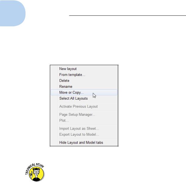
After you create a layout, you can delete, copy, rename, and otherwise manipulate it by clicking Quick View Layouts on the status bar and rightclicking a preview image. If you’re using layout tabs rather than buttons, right-click a tab to display the menu or simply drag the tab to a new position. Figure 5-3 shows the menu options when you right-click a layout tab.
Figure 5-3: The Quick View Layouts right-click menu.
The From Template option refers to layout templates. After you create layouts in a template (DWT) or a drawing (DWG) file, you can use the From Template option to import these layouts into the current drawing. For details, see the LAYOUT command’s Template option in the Command Reference section of online help.
Many drawings require only one paper space layout. If you always plot the same view of the model and always plot to the same device and on the same size paper, a single paper space layout should suffice. If you want to plot your model in different ways (for example, at different scales, with different layers visible, with different areas visible, or with different plotted line characteristics), you may want to create additional paper space layouts.
www.it-ebooks.info
Chapter 5: Planning for Paper 117
Lost in paper space
After you create a paper space layout, you suddenly have two views of the same drawing geometry: the view in your original model space and the new layout’s view (perhaps decorated with a handsome title block and other accoutrements of plotting nobility). It’s important to realize that both views are of the same geometry. If you change the model geometry on one view, you’re changing it everywhere because all layouts display the same model space objects.
When you make a layout current, you can switch the active space between paper space (that is, drawing and zooming on the sheet of paper) and model space (drawing and zooming on the model, inside the viewport) in several ways, including the following:
In the drawing area, double-click inside a viewport boundary to move the crosshairs into model space in that viewport. Alternatively, you can double-click outside all viewports (for example, in the gray area outside the sheet) to move the crosshairs into paper space.
Click the Maximize/Minimize Viewport button on the status bar. (For more information, see Chapter 2.)
Type MSPACE (the command alias is MS) or PSPACE (PS) at the keyboard.
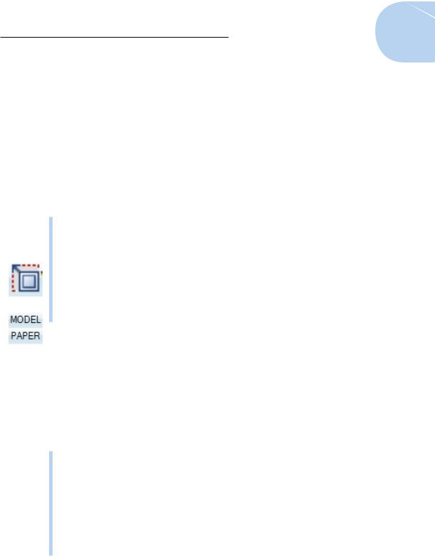
Click the MODEL/PAPER button on the status bar.
When the crosshairs are in model space, anything you draw or edit changes the model in model space and therefore, through the viewports, on all paper space layouts. When the crosshairs are in paper space, anything you draw appears only on that one layout. It’s as though you were drawing on an acetate sheet over the top of that sheet of plotter paper — the model beneath remains unaffected.
This behavior can make your brain hurt until you get used to it. To avoid confusion, stick with the following approach (at least until you’re more familiar with paper space):
If you want to edit the model: Do so in full-screen model space. Click the Model tab if tabs are displayed, or click the Model button if tabs are hidden. (The Model button is the one with the little black icon; don’t confuse it with the MODEL/PAPER button, which switches between model and paper space within the same layout.) Don’t try to edit the model in a paper space viewport — it’s a very inefficient use of your screen space.
If you want to edit a particular layout without affecting the model: Use one of the methods we describe to make that layout current, and make sure that the crosshairs are in paper space.
www.it-ebooks.info
118 Part I: AutoCAD 101
Spaced out
When you start working in layouts, it may not always be crystal clear whether you’re in model space or paper space. The status bar button will help — it will say PAPER if you’re in paper space or MODEL if you’re in the other place. Here are a few other ways to tell your layout spaces apart:
Check the crosshairs. If you’re in paper space, you can move the crosshairs over the entire drawing area. If you’re in model space, you can move the crosshairs only within the currently active viewport; if you try to move the crosshairs outside the viewport, they turn into a Windows selection arrow.
Select some model geometry. Try clicking some objects that you know are in model space. If you can select them and they highlight, then you’re in model space. If nothing happens when you click them, they’re inaccessible because you’re in paper space.
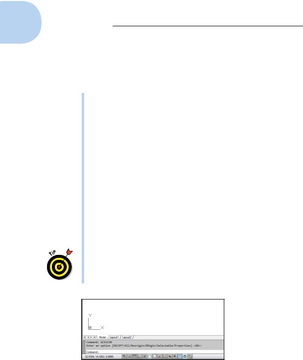
Check the UCS icon. The UCS (for User Coordinate System) icon is the symbol at the lower-left corner of the drawing area. The model space icon takes the shape of two lines at right angles to each other, with the letters indicating the direction of the X-axis and the Y-axis. (If you’ve configured AutoCAD to use the 2D UCS icon, the W stands for the World Coordinate System.) The paper space icon is triangular, and the closed, three-sided shape represents a flat plane. If you don’t see such a symbol, type UCSICON and press Enter; then type either ON to display the UCS icon in the lower-left corner of the display, or OR to display it at the drawings origin (that is, 0,0 coordinates), as shown in Figure 5-4. We explain more about user coordinate systems in Chapter 7.
Figure 5-4 shows the 2D UCS icon. By default, AutoCAD displays the 3D UCS icon, even when you’re working in the Drafting & Annotation
workspace. You can switch to the 2D style, adjust the icon size, and tell AutoCAD to display the icon in three colors by entering the UCSICON command and then clicking Properties.
Figure 5-4: Displaying the 2D style UCS icon.
www.it-ebooks.info

Chapter 5: Planning for Paper 119
A view(port) for drawing in
A viewport is a paper space object — a window into your drawing sheet — through which you view model space objects from paper space. By default, when you create a new layout, a large single viewport is created.
The viewports we talk about in this chapter are paper space viewports. You can also create viewports in model space, but they’re completely different animals. Model space viewports are also known as tiled viewports because (like bathroom tiles) they can’t have any space between them. You can use tiled viewports to look closely at widely separated areas of your screen. What’s potentially confusing is that AutoCAD uses the same command name, and even the same dialog box, for creating the two different types of viewports. For this chapter, make sure that you’re in paper space when you create viewports.
Paper space viewports are assigned drawing scales, and you can have multiple viewports with different scales on the same layout. For example, one viewport can show the floor plan of an exhibit space at 1⁄4" to one foot, and another viewport can show an enlarged view of a display cabinet at 1"=1'.
Because the individual viewports are scaled, the entire layout can be plotted at 1:1.
The Create Layout Wizard is fine when you’re starting out, but most real drawings have unique, nonstandardized arrangements of viewports. When creating layouts, it’s often easiest to create viewports from scratch. The following procedure explains how:
1.Using one of the techniques described in the “Creating a layout” section, earlier in this chapter, create a new layout in your drawing.
For example, click Quick View Layouts to display the preview images, and then right-click any of the images and choose New Layout. A new layout is added to the end of the image strip.
2.Click the image for the new layout to open it.
A new layout appears in the drawing window, showing the default sheet area and a single rectangular viewport centered on the sheet. You aren’t going to use this viewport.
3.Move the crosshairs over the viewport boundary and click to select it. Press the Delete key.
Although they don’t behave like other drawing objects, viewports are objects, just like lines or circles. And like any other drawing objects, they can be selected and moved, copied, resized, arrayed — or deleted.
www.it-ebooks.info
120 Part I: AutoCAD 101
4.On the Ribbon, click the Layout tab; then in the Layout Viewports panel, choose Rectangular.
AutoCAD prompts you to pick the first corner for the new viewport.
You must be in paper space for these steps to work as described. If the Rectangular button (we know; they’re all rectangular — we mean the one that says “Rectangular”) is grayed out, you’re still in model space.
5.Pick a point somewhere on the blank page to locate the first corner of the new viewport.
AutoCAD prompts you to pick the second corner.
6.Pick another point to place the second corner of the new viewport.
AutoCAD draws the viewport, and the model space geometry appears inside it. Next, specify a drawing scale for your viewport(s).
Specifying the correct viewport scale sooner rather than later bestows a couple of important benefits:
•Correctly scaling viewports allows you to use annotative documen- tation objects such as text, dimensions, hatch patterns, blocks, and noncontinuous (dash-dot) linetypes. We introduce you to annotative objects in Chapter 13.
•Correctly scaling all your viewports allows you to easily plot the completed layout at a scale of 1:1, while retaining individual, true- to-scale viewports.
7.Double-click inside the viewport you want to apply a scale to.
Model space becomes active, as it must, because that’s the space you have to scale. The Viewport Scale button appears toward the right side of the status bar when model space is activated in a layout.
8.Click the Viewport Scale button on the status bar.
Clicking the Viewport Scale button opens a pop-up list of every drawing scale registered in the scales list — including metric scales even if you’re working in an English-units drawing, and vice versa.
Most of the time, for most people, there are way too many scales in the lists you see in the Viewport Scale button and the Plot dialog box. AutoCAD has a handy-dandy Edit Drawing Scales dialog box that lets you remove those imperial scales if you never work in feet and inches and vice versa, if you work only in metric. To run through your scales,
choose Scale List from the Annotation Scaling panel on the Annotate tab, or type SCALELISTEDIT and press Enter to open the Edit Drawing Scales dialog box. If (more likely “when”) you make a mistake, the Reset button in the Edit Drawing Scales dialog box will restore all the default scales.
9.Find the scale you want to apply to the active viewport and select it from the list.
The display zooms in or out to adjust to the chosen viewport scale.
www.it-ebooks.info