

166 Part II: Let There Be Lines
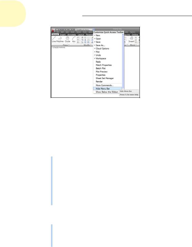
Figure 8-1: You can display the classic menu bar if you want to.
The Straight and Narrow: Lines, Polylines, and Polygons
As we harp on a bunch of times elsewhere in this book, CAD programs are for precision drawing, so you’ll spend a lot of your AutoCAD time drawing objects composed of straight-line segments. The rest of this chapter covers these commands:
LINE (L): Draws a series of straight-line segments; each segment is a separate object.
PLINE (PL): Draws a polyline — a series of straightand/or curved-line segments. (Yes, I’m cheating a bit here — curvy things are covered in Chapter 9 — but we don’t want you to have to read about one command in two different places!) All the segments remain connected to each other as a single object.
RECTANG (REC): Draws a polyline in the shape of a rectangle.
POLYGON (POL): Draws a polyline in the shape of a regular polygon (that is, a closed shape with all sides equal and all angles equal).
The following additional straight-line drawing commands are also available in AutoCAD:
RAY: Draws a line that starts at a point and just keeps on going; a ray therefore is a line that extends infinitely in one direction.
XLINE (XL): Draws a line that passes through a point and extends infinitely in both directions. The question of the day is, which of these two lines is longer?
www.it-ebooks.info

Chapter 8: Along the Straight and Narrow 167
The RAY and XLINE commands are used to draw construction lines that guide the construction of additional geometry. Drawing construction lines is less common in AutoCAD than in some other CAD programs. AutoCAD’s many precision techniques often provide more efficient methods for creating new geometry than adding construction lines to your drawing does. In particular, object snap tracking (discussed in Chapter 7) and parametrics (discussed in Chapter 19) usually eliminate all need for construction geometry or even for a mitre line when creating orthographic views.
Toeing the line
The LINE command in AutoCAD draws a series of one or more visually connected line segments. Although the lines appear to be physically connected, in fact, each segment, or piece of a line with endpoints, is a separate object. This construction doesn’t seem like a big deal until you try to move (or otherwise edit) a series of segments that you drew with the LINE command; you must select every piece separately. To avoid such a hassle, use polylines (described in the following section), not lines (or lines and arcs), when you want the connected segments to act as a single object.
If you’re used to drawing lines in other programs, you may find it confusing at first that AutoCAD’s LINE command doesn’t stop after you draw a single segment. AutoCAD keeps prompting you to specify additional points so that you can draw a series of (apparently) connected segments. When you’re finished drawing segments, just press Enter to finish the LINE command.
Unlike a lot of the AutoCAD drawing commands, LINE doesn’t offer a bunch of potentially confusing options. It has a Close option to create a closed polygonal shape and an Undo option to remove the most recent segment that you drew.
Like all drawing commands, LINE puts the line segments that it draws on the current layer and uses the current color, linetype, lineweight, transparency, and plot-style properties. When you’re doing real drafting, as opposed to just experimenting, make sure of the following:
Think about setting these properties before you start drawing.
Although you can easily change an object’s layer or other object properties, it’s often more efficient to set properties first. (We recommend that you set color, linetype, lineweight, transparency, and, if you’re using named plot styles, plot style to ByLayer.) See Chapter 6 for information on setting the current properties with the tools on the Home tab’s Properties panel.
Use the right precision tools. Make sure that you use one of AutoCAD’s precision tools, such as object snaps, typed coordinates, or tracking, to ensure that you specify each object point precisely. Chapter 7 describes these tools.
www.it-ebooks.info

168 Part II: Let There Be Lines
Follow these steps to draw a series of line segments by using the LINE command:
1.Set an appropriate layer to be current.
2.Click the Home tab on the Ribbon.
The panels on the Home tab contain the most commonly used commands in AutoCAD.
3.Click the Line button on the Draw panel of the Ribbon’s Home tab, or type L and press Enter.
AutoCAD starts the LINE command and prompts you to select the first point.
4.Specify the starting point by clicking a point or typing coordinates.
Remember to use one of the precision techniques we describe in Chapter 7 if you’re doing real drafting. For the first point, you can type coordinates, pick a precise point if snap is turned on, or use object snap if other objects already exist in the drawing. AutoCAD prompts you
to specify the other endpoint of the first line segment. The command window prompt shows
Specify next point or [Undo]:
You can also see command prompts at the Dynamic Input tooltip beside the crosshairs by pressing the down-arrow key (press F12 or click the Dynamic Input status bar button to enable Dynamic Input mode). The arrow icon on the Dynamic Input tooltip is your indicator that there are options available.
5.Specify additional points by clicking or typing.
Again, use one of the AutoCAD precision techniques if you’re doing real drafting. For the second and subsequent points, all the techniques mentioned in Step 4 work well, as do ortho, polar, object snap tracking, and direct distance entry.
After you specify the third point, AutoCAD adds the Close option. The command prompt shows
Specify next point or [Close/Undo]:
6.When you’re finished drawing segments, end with one of these steps:
•Keep the figure open. Either press Enter, or right-click anywhere in the drawing area and choose Enter from the right-click menu to leave the figure open.
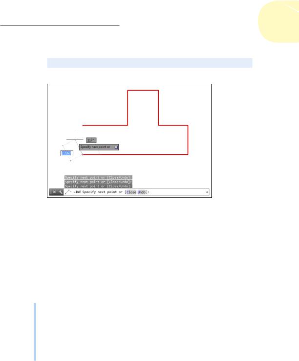
•Close the figure. Type C and press Enter, or press the down arrow on your keyboard and choose Close from the menu (shown in Figure 8-2) to close the figure.
www.it-ebooks.info
Chapter 8: Along the Straight and Narrow 169
In either case, the blank command prompt indicates that the LINE command is finished:
Command:
Figure 8-2: Line it up — drawing line segments with the LINE command.
Connecting the lines with polyline
The LINE command is fine for many drawing tasks, but the PLINE command is better for others. Experience will help you to choose. The PLINE command draws a special kind of object called a polyline. You may hear CAD drafters refer to a polyline as a pline (rhymes with beeline) because of the command name. This has nothing to do with the queue at a busy restroom.
The most important differences between the LINE and PLINE commands are these:
The LINE command draws a series of separate line segments. Even though they appear to be connected on the screen, each segment is a separate object. If you move one line segment, the other segments that you drew at the same time don’t move with it.
The PLINE command draws a single, connected, multisegment object.
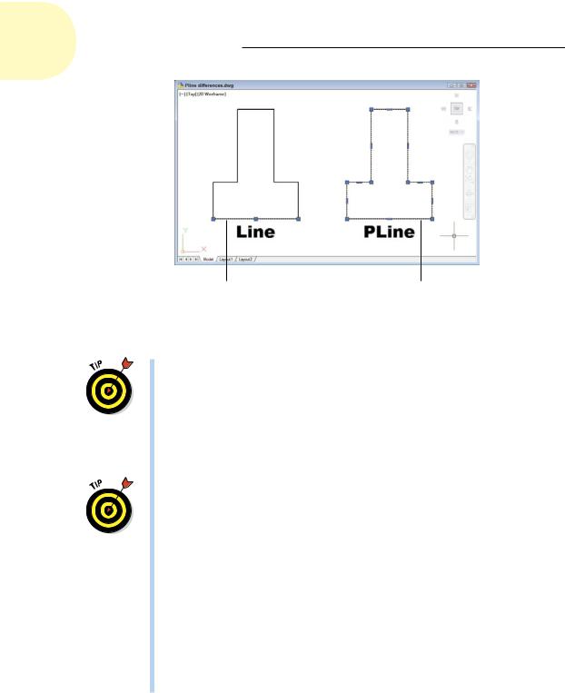
If you select any segment for editing, your changes affect the entire polyline. Figure 8-3 shows how the same sketch drawn with the LINE and the PLINE commands responds when you select one of the objects.
www.it-ebooks.info
170 Part II: Let There Be Lines
Each segment is |
All segments |
a separate object. |
form one object. |
Figure 8-3: Results of drawing with the LINE and PLINE commands.
Use PLINE rather than LINE in most cases where you need to draw a series of connected line segments. If you’re drawing a series of end-to- end segments, there’s a good chance that those segments are logically connected — for example, they might represent the outline of a single object or a continuous pathway. If the segments are connected logically, it makes sense to keep them connected in AutoCAD. The most obvious practical benefit of grouping segments together into a polyline is that many editing operations are more efficient when you use polylines. When you select any segment in a polyline for editing, the entire polyline is selected.
As covered in Chapter 19, using parametrics on line segments can often produce the same results as using a PLINE.
The PLINE command can draw curved segments as well as straight ones. If you want a combination of separate linear and curved segments, you must switch back and forth between the LINE and ARC commands (we cover arcs in Chapter 9). With PLINE, you can switch between linear or circular-curve sections by choosing the command options described in the steps that come after this list.
Polylines can have width. Polyline segment width is visually similar to AutoCAD’s lineweight object property, except that polyline width can vary from segment to segment, and individual segments can be tapered. But wait! There’s more! After drawing a polyline, you can have it automatically reshape itself into a smooth, flowing curve based on the vertex points you selected.
www.it-ebooks.info
Chapter 8: Along the Straight and Narrow 171
After you create a polyline, you can adjust its segments by grip editing any of the vertex points. (The little squares on the vertices in Figure 8-3 are called grips; see Chapter 10 for details on grip editing.) For more complicated poly- line-editing tasks, you can use the PEDIT command to edit the polyline, or you can convert the polyline to a collection of line and arc segments by using the EXPLODE command — although you lose any width defined for each segment when you explode a polyline. For more information on these two commands, look them up in the index of the online help.
Drawing polylines composed of straight segments is pretty much like drawing with the LINE command, as demonstrated in the following procedure.
The PLINE command has lots of options, so watch the prompts! If Dynamic Input is on, use the down-arrow key to see the options listed near the crosshairs, or right-click to display the PLINE right-click menu, or simply read the command line.
To draw a polyline composed of straight segments, follow these steps:
1.Set an appropriate layer to be current.
2.Click the Polyline button on the Ribbon’s Draw panel or type PL and press Enter.
AutoCAD starts the PLINE command and prompts you to specify a start point.
3.Specify the starting point by clicking a point or typing coordinates.
AutoCAD displays the current polyline segment line width at the command line and prompts you to specify the other endpoint of the first polyline segment:
Current line-width is 0.0000
Specify next point or [Arc/Halfwidth/Length/Undo/
Width]:
4.If the current line width isn’t zero, change it to zero by typing W to select the Width option, and then entering 0 as the starting and ending widths, as shown in the following command-line sequence:
Specify next point or [Arc/Halfwidth/Length/Undo/Width]: W
Specify starting width <0.0000>: 0
Specify ending width <0.0000>: 0
Specify next point or [Arc/Halfwidth/Length/Undo/
Width]:
Despite what you may think, a zero-width polyline segment isn’t the AutoCAD equivalent of drawing with invisible ink. Zero width means “display this segment using the normal, single-pixel width on the screen and plot as thin as possible.”
5. Specify additional points by clicking or typing.
www.it-ebooks.info
172 Part II: Let There Be Lines
After you specify the second point, AutoCAD adds the Close option to the prompt. The command line shows
Specify next point or [Arc/Close/Halfwidth/Length/ Undo/Width]:
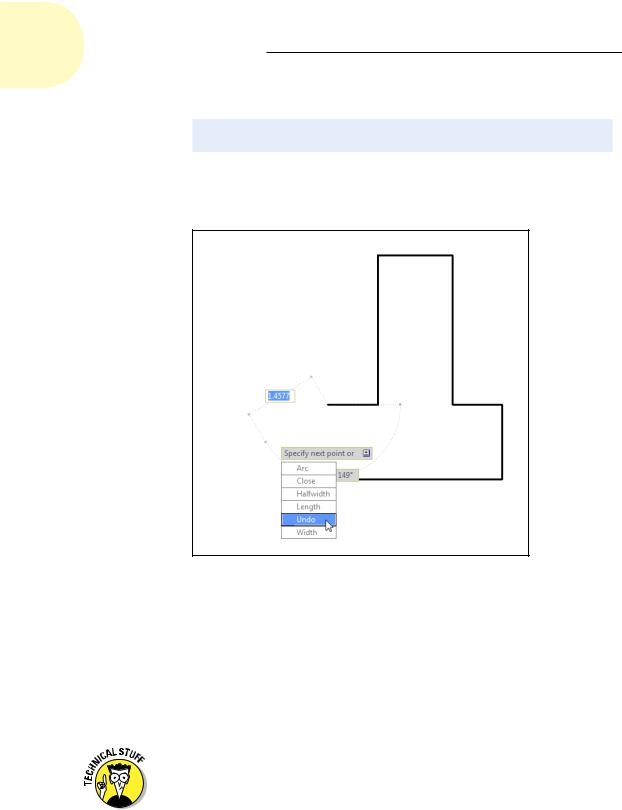
In addition, you can view and choose options from the Dynamic Input options list, shown in Figure 8-4, by pressing the down arrow on your keyboard.
Figure 8-4: Making a PLINE.
6.After you finish drawing segments, either press Enter (to leave the figure open) or type C and press Enter (to close it).
AutoCAD draws the final segment. The blank command line indicates that the PLINE command is finished.
In the following procedure, we spice things up a bit and give you a preview of coming (curvy) attractions (in Chapter 9) by adding an arc segment to a polyline.
Just so you know, curved segments in polylines are circular arcs — pieces of circles with center points that you can draw with AutoCAD’s ARC command. AutoCAD can draw other kinds of curves, including ellipses and splines, but not within the PLINE command.
www.it-ebooks.info

Chapter 8: Along the Straight and Narrow 173
To draw a polyline that includes curved segments, follow these steps:
1.Repeat Steps 1 through 5 of the previous procedure.
2.When you’re ready to add one or more arc segments, type A and press
Enter to select the Arc option.
The prompt changes to show arc segment options. Most of these options correspond to the many ways of drawing circular arcs in AutoCAD; see the section on arcs in Chapter 9. The command line shows
Specify endpoint of arc or [Angle/CEnter/CLose/ Direction/Halfwidth/Line/Radius/Second pt/Undo/Width]:
3.Specify the endpoint of the arc by clicking a point or typing coordinates.
AutoCAD draws the curved segment of the polyline. The prompts continue to show arc segment options.
Your options at this point include
•Specifying additional points to draw more arc segments
•Choosing another arc-drawing method (such as Center or Second pt)
•Returning to drawing straight-line segments with the Line option
In this example, you return to drawing straight-line segments.
Perhaps the most useful of the alternative arc-drawing methods is Second pt. That gives you more control over the direction of the arc, but at the cost of losing tangency of adjacent segments. Sometimes it’s best not to go off on a tangent, anyway.
4. Type L and press Enter to select the Line option.
Specify endpoint of arc or [Angle/CEnter/CLose/
Direction/Halfwidth/Line/Radius/Second pt/
Undo/Width]: L
The prompt changes back to showing straight-line segment options.
Specify next point or [Arc/Close/Halfwidth/Length/
Undo/Width]:
5.Specify additional points by clicking or typing.
6.After you’re finished drawing segments, either press Enter, or type C and press Enter.
Figure 8-5 shows some of the things that you can draw with the PLINE command by using straight segments, arc segments, varying-width segments, or a combination of all of them.
www.it-ebooks.info