

7
Preciseliness Is Next to CADliness
In This Chapter
Typing coordinates at the keyboard
Getting to know AutoCAD’s Coordinate Systems
Snapping to object features
Using other precision drawing and editing techniques
Drawing precision is vital to good CAD drafting practice, even more than for manual drafting. (Accuracy, of course, is vital to both types of
drafting — if you’re sketchy on the difference between accuracy and precision, look ahead to the “CAD precision versus accuracy” sidebar in this chapter.) If you think CAD managers get a little tense when you assign properties directly to objects instead of ByLayer, wait until you see them lay into someone (we sincerely hope it’s not you!) who doesn’t use preci-
sion techniques when creating drawings in AutoCAD.
Controlling Your Precision
In AutoCAD, lack of precision makes later editing, hatching, and dimensioning tasks much more difficult and time consuming. Keep these facts in mind:
Small errors in precision in the early stages of creating or editing a drawing often have a big effect on productivity and precision later.
CAD drawings are often used for much more than just giving a picture to someone. If they’ve been
properly created, they can also be queried for things like sizes, areas, and quantities.
Drawings may guide manufacturing and construction projects; drawing data may drive automatic manufacturing machinery. Huge amounts of money and even lives can ride on a drawing’s precision.
www.it-ebooks.info
148 Part II: Let There Be Lines
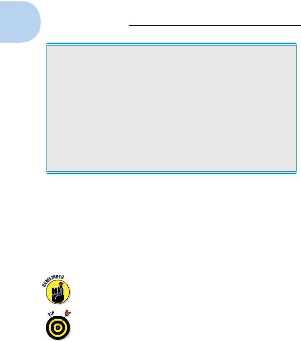
CAD precision versus accuracy
You often hear the words precision and accuracy used interchangeably, but it’s useful to understand the difference. In this book, we use precision to mean controlling the placement of objects so they lie exactly where you want them to lie in the drawing. For example, lines whose endpoints meet must meet exactly, and a circle that’s supposed to be centered on the coordinates 0,0 must be drawn with its center exactly at 0,0. We use accuracy to refer to the degree to which your drawing matches its real-world counterpart. An accurate floor plan is one in which the dimensions of the CAD objects equal the dimensions of the as-built house. In a sense,
then, it’s not the drawing that should be accurate — it’s the house!
CAD precision usually helps produce accurate drawings, but that’s not always the case. You can produce a precise CAD drawing that’s inaccurate because you started from inaccurate information (for example, the contractor gave you a wrong field measurement). Or you might deliberately exaggerate certain distances to convey the relationship between objects more clearly on the plotted drawing. Even where you must sacrifice accuracy, aim for precision.
In recognition of these facts, a passion for precision permeates the profession. Precision is one of the characteristics that separates CAD from ordinary illustration-type drawing work. The sooner you get fussy about precision in AutoCAD, the happier everyone is.
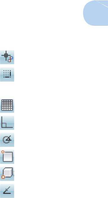
When we talk about drawing things precisely, we mean using precision techniques and tools to specify points and distances with as much exactness as the program allows. Luckily, AutoCAD provides a comprehensive package of tools for doing just that. Table 7-1 lists the more important AutoCAD precision techniques, along with visual cues to the status bar buttons that you click to toggle some of the features.
As we describe in Chapter 2, you can switch the display on status bar buttons between text and icons by right-clicking any of those buttons and selecting or deselecting Use Icons. Table 7-1 shows the icons and lists the text for both alternatives.
Precision is especially important when you’re drawing or editing geometry — the lines, arcs, and so on that make up whatever you’re representing in the CAD drawing. Precision placement usually is less important with notes, leaders, and other annotations that describe, not show.
www.it-ebooks.info
|
|
|
Chapter 7: Preciseliness Is Next to CADliness 149 |
|||
|
|
|
||||
|
|
|
|
|
||
|
Table 7-1 |
|
|
Precision Tools and Techniques |
|
|
|
Technique |
Status Bar |
Status Bar |
Description |
||
|
|
Button |
Button |
|
|
|
|
|
Label |
Icon |
|
|
|
|
Infer |
INFER |
|
Applies geometric constraints at |
|
|
|
Constraints |
|
|
|
specific pick points (not in AutoCAD |
|
|
|
|
|
|
LT); see Chapter 19. |
|
|
|
|
|
|
|
|
|
Snap mode |
SNAP |
|
Forces the crosshairs to move on |
||
|
|
|
|
|
an imaginary grid of equally spaced |
|
|
|
|
|
|
hot spots. |
|
|
|
|
|
|
|
|
|
Polar snap |
— |
— |
Forces the crosshairs to move spe- |
||
|
|
|
|
|
cific distances along polar tracking |
|
|
|
|
|
|
angles. |
|
|
Grid display |
GRID |
|
Displays a nonprinting reference |
|
|
|
|
|
|
|
grid of lines or dots arranged in |
|
|
|
|
|
|
rows or columns. |
|
|
|
|
|
|
|
|
|
Ortho mode |
ORTHO |
|
Forces the crosshairs to move |
||
|
|
|
|
|
horizontally or vertically from the |
|
|
|
|
|
|
previous point. |
|
|
|
|
|
|
|
|
|
Polar tracking |
POLAR |
|
Causes the crosshairs to jump to |
||
|
|
|
|
|
specified angles. |
|
|
|
|
|
|
|
|
|
Object snap |
OSNAP |
|
Enables picking specific points on |
||
|
|
|
|
|
existing drawing objects multiple |
|
|
|
|
|
|
times. |
|
|
|
|
|
|
|
|
|
3D Object |
3DOSNAP |
|
Enables picking specific points on |
||
|
snap |
|
|
|
existing 3D objects multiple times |
|
|
|
|
|
|
(not in AutoCAD LT). |
|
|
|
|
|
|
|
|
|
Object snap |
OTRACK |
|
Causes the crosshairs to locate |
||
|
tracking |
|
|
|
new points based on multiple |
|
|
|
|
|
|
object snap points. |
|
|
|
|
|
|
|
|
|
Object snap |
— |
— |
Enables picking specific points on |
||
|
overrides |
|
|
|
existing drawing objects one time |
|
|
|
|
|
|
only. |
|
|
Coordinate |
— |
— |
Enables you to type exact X,Y or |
|
|
|
input |
|
|
|
polar coordinates. |
|
|
Direct distance |
— |
— |
Enables you to locate a point by |
|
|
|
entry |
|
|
|
typing a distance and moving the |
|
|
|
|
|
|
crosshairs to show the direction. |
|
www.it-ebooks.info
150 Part II: Let There Be Lines
Before you draw objects, always check the status bar buttons and set them according to your precision needs.
A button that looks lit (that is, just a little brighter than its neighbors — typically, a light blue) indicates that the feature is on.
A button that looks dimmed (typically, dark gray) indicates that the feature is off.
Keyboard capers: Coordinate input
The most direct way to enter points precisely is to type numbers at the keyboard. AutoCAD uses these keyboard coordinate entry formats:
Absolute Cartesian (X,Y) coordinates in the form X,Y (for example, 7,4)
Relative X,Y coordinates in the form @X,Y (for example, @3,2)
Relative polar coordinates in the form @distance<angle (for example,
@6<45)
Understanding AutoCAD’s coordinate systems
AutoCAD stores locational data for every object in a drawing based on a centuries-old system of Cartesian, or X,Y, coordinates.
Cartesian coordinates are named for French philosopher René “I think, therefore I am” Descartes. In his Discourse on Method, Descartes came up with the idea of locating any point on a planar surface by measuring its distance from the intersection of a pair of axes (that’s axes as in more than one axis, not the tool for chopping wood). By convention, the intersection of those axes (called, also by convention, the X-axis and the Y-axis) are perpendicular to one another, and their intersection point is identified as 0,0. The logical next step in this system of X,Y coordinates is to introduce a third axis (called, what else, the Z-axis), perpendicular to the plane defined by the X- and Y-axes. This one shares the X,Y intersection point of 0,0 and so its coordinates are identified as 0,0,0.
Theoretically, any point in three-dimensional space can be located by a set of X,Y,Z coordinates. And by extension, every point in an AutoCAD drawing file can be identified by its X,Y,Z coordinates (in most 2D drawings, the Z-coordinate is 0). This system of coordinates is referred to in AutoCAD as the World Coordinate System, or WCS.
Introducing User Coordinate Systems
Many times, it’s convenient to define additional coordinate systems to make drawing things a little easier, so AutoCAD lets you roll your own. These non– World Coordinate Systems are called User Coordinate Systems (UCS for short),
www.it-ebooks.info
Chapter 7: Preciseliness Is Next to CADliness 151
and they’re so widely used that UCS now refers to every coordinate system in AutoCAD.
Why would you want to diverge from the standard WCS? Well, the most common reason is that you might be working in 3D, and it’s way easier to calculate and enter coordinates if they’re based on the plane you want to work on. For example, say you’re modeling one of those old-fashioned wedgeshaped rubber doorstops, and you want to add the manufacturer’s logo to the sloping surface of the wedge. That’s not easy if you stay in the WCS, but AutoCAD lets you set a new UCS based on that sloping surface. After that UCS is made current, you draw in it just as you draw in the WCS. (We have more to say about UCSs in 3D in Chapter 21.)
Think of the real world. A specific latitude and longitude (WCS) always identifies the same point, but the actual location for a description like “the corner of 33rd and Main” depends on which city you’re in (UCS).
UCSs can be useful on two dimensions as well as three. The WCS assumes the north direction is straight up — 90 degrees, according to AutoCAD’s defaults — but your drawing might work better on a sheet where north pointed to the left. Easy enough — create a UCS with north pointing left (we’ll leave you to look up this process in the online help — we only have so many pages!)
It’s generally easier to create a UCS by typing options at the command line, but after they’re created, they’re easier to manage through the UCS dialog box. Type UCSMAN and press Enter to display this dialog box.
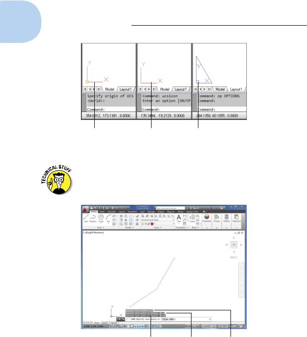
AutoCAD’s UCS icon shows you clearly whether you’re in paper space or model space, and almost as clearly whether you’re in the WCS or a UCS if you’re in model space. Figure 7-1 shows AutoCAD 2013’s variations on the theme.
You can use the UCS command in paper space as well as model space, but it’s almost always a bad idea. Leave paper space in the WCS to make your plotting a whole lot easier.
The UCS icon is selectable; click it, and grips appear at the origin and the ends of the axis indicators. You can drag the icon by its grips to set a new UCS. We cover this feature more fully in Chapter 21.
Drawing by numbers
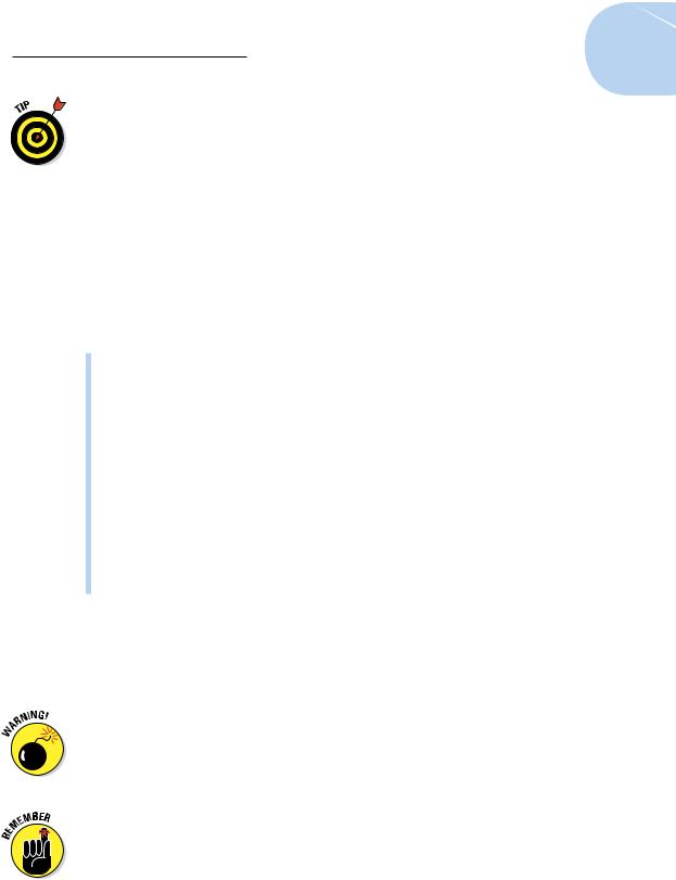
AutoCAD locates absolute X,Y coordinates with respect to the 0,0 point (otherwise known as the origin) of the drawing — usually its lower-left corner. AutoCAD locates relative X,Y coordinates and relative polar coordinates with respect to the previous point that you picked or typed. Figure 7-2 demonstrates how to use all three coordinate formats to draw a pair of line seg-
ments that start at absolute coordinates 2,1; then go 3 units to the right and 2 units up relative to the first point; then relative to that point, go 4 units at an angle of 60 degrees.
www.it-ebooks.info
152 Part II: Let There Be Lines
Icon indicates |
Icon indicates User |
Icon indicates |
World Coordinate |
Coordinate System. |
paper space. |
System. |
|
|
Figure 7-1: The UCS icon shows you your current coordinate system.
In case you’re wondering, AutoCAD also understands absolute polar coordinates in the form distance<angle, but this format is almost never useful.
Relative polar |
Relative X, Y |
Absolute X, Y |
coordinates |
coordinates |
coordinates |
Figure 7-2: Coordinating from the keyboard.
www.it-ebooks.info
Chapter 7: Preciseliness Is Next to CADliness 153
You can find out the X,Y location of your crosshairs by moving them around in the drawing area and reading the coordinate values at the left end of the status bar. The X,Y coordinates should change as you move the crosshairs. If the coordinates don’t change, click the drawing coordinates area until you see <Coords on> in the command window.
Astute observers of the full version of AutoCAD will have noticed that there are three numbers at the left end of the status bar (AutoCAD LT is numerically challenged). AutoCAD is actually showing you the X,Y coordinates of the crosshairs and the current elevation (the Z value). However, in 2D drafting, the Z value is (or should be) 0, so you can continue calling them X,Y coordinates.
Although it’s not apparent at first, there are, in fact, four coordinate display modes. Clicking the coordinates readout cycles through them, as follows:
Off (<Coords off>): The status bar coordinate readout is dimmed, and the coordinate values don’t update until you pick a point.
On, showing X,Y coordinates (<Coords on>): The coordinate readout appears black, and the absolute X,Y coordinates update continuously as you move the crosshairs. If no command is active, clicking the coordinates readout alternates between this mode and <Coords off>.
On, showing polar coordinates (<Coords on>): This mode, which displays distance and angle relative to the last point picked rather than absolute X,Y values, appears if a command is active and AutoCAD is waiting for you to pick a point.
On, showing geographic coordinates (<Coords on>): This mode displays coordinates as the latitude and longitude values, but can be used only after you set the drawing’s geographic location with the, what else, GeographicLocation command.
If you start a command such as LINE, pick a point, and then click the Coordinates area a few times, the display changes from coordinates off to live absolute coordinates (X,Y position) to live polar coordinates (distance and angle from the previous point). Displaying live polar coordinates is the most informative mode most of the time.
When you type coordinates at the command line, do not add any spaces because AutoCAD interprets a space as though you’ve pressed Enter. This “Spacebar = Enter” weirdness is a productivity feature that’s been in AutoCAD forever. It’s easier to find the spacebar than the Enter key when
you’re entering lots of commands and coordinates in a hurry — and it’s especially handy for touch typists who are all thumbs.
If you’re working in AutoCAD’s Architectural or Engineering units, the default unit of entry is inches, not feet. Here are some things to consider about entering numeric values when you work in feet and inches:
www.it-ebooks.info