

- •About the Authors
- •Dedication
- •Authors’ Acknowledgments
- •Table of Contents
- •Introduction
- •What’s Not (And What Is) in This Book
- •Mac attack!
- •Who Do We Think You Are?
- •How This Book Is Organized
- •Part I: AutoCAD 101
- •Part II: Let There Be Lines
- •Part III: If Drawings Could Talk
- •Part IV: Advancing with AutoCAD
- •Part V: On a 3D Spree
- •Part VI: The Part of Tens
- •But wait . . . there’s more!
- •Icons Used in This Book
- •A Few Conventions — Just in Case
- •Commanding from the keyboard
- •Tying things up with the Ribbon
- •Where to Go from Here
- •Why AutoCAD?
- •The Importance of Being DWG
- •Seeing the LT
- •Checking System Requirements
- •Suddenly, It’s 2013!
- •AutoCAD Does Windows (And Office)
- •And They’re Off: AutoCAD’s Opening Screens
- •Running with Ribbons
- •Getting with the Program
- •Looking for Mr. Status Bar
- •Let your fingers do the talking: The command window
- •The key(board) to AutoCAD success
- •Keeping tabs on palettes
- •Down the main stretch: The drawing area
- •Fun with F1
- •A Simple Setup
- •Drawing a (Base) Plate
- •Drawing rectangles on the right layers
- •Circling your plate
- •Nuts to you
- •Getting a Closer Look with Zoom and Pan
- •Modifying to Make It Merrier
- •Hip-hip-array!
- •Stretching out
- •Crossing your hatches
- •Following the Plot
- •A Setup Roadmap
- •Choosing your units
- •Weighing up your scales
- •Thinking annotatively
- •Thinking about paper
- •Defending your border
- •A Template for Success
- •Making the Most of Model Space
- •Setting your units
- •Making the drawing area snap-py (and grid-dy)
- •Setting linetype and dimension scales
- •Entering drawing properties
- •Making Templates Your Own
- •Setting Up a Layout in Paper Space
- •Will that be tabs or buttons?
- •View layouts Quick(View)ly
- •Creating a layout
- •Copying and changing layouts
- •Lost in paper space
- •Spaced out
- •A view(port) for drawing in
- •About Paper Space Layouts and Plotting
- •Managing Your Properties
- •Layer one on me!
- •Accumulating properties
- •Creating new layers
- •Manipulating layers
- •Using Named Objects
- •Using AutoCAD DesignCenter
- •Copying layers between drawings
- •Controlling Your Precision
- •Keyboard capers: Coordinate input
- •Understanding AutoCAD’s coordinate systems
- •Grab an object and make it snappy
- •Other Practical Precision Procedures
- •Introducing the AutoCAD Drawing Commands
- •The Straight and Narrow: Lines, Polylines, and Polygons
- •Toeing the line
- •Connecting the lines with polyline
- •Squaring off with rectangles
- •Choosing your sides with polygon
- •(Throwing) Curves
- •Going full circle
- •Arc-y-ology
- •Solar ellipses
- •Splines: The sketchy, sinuous curves
- •Donuts: The circles with a difference
- •Revision clouds on the horizon
- •Scoring Points
- •Commanding and Selecting
- •Command-first editing
- •Selection-first editing
- •Direct object manipulation
- •Choosing an editing style
- •Grab It
- •One-by-one selection
- •Selection boxes left and right
- •Perfecting Selecting
- •AutoCAD Groupies
- •Object Selection: Now You See It . . .
- •Get a Grip
- •About grips
- •A gripping example
- •Move it!
- •Copy, or a kinder, gentler Move
- •A warm-up stretch
- •Your AutoCAD Toolkit
- •The Big Three: Move, Copy, and Stretch
- •Base points and displacements
- •Move
- •Copy
- •Copy between drawings
- •Stretch
- •More Manipulations
- •Mirror
- •Rotate
- •Scale
- •Array
- •Offset
- •Slicing, Dicing, and Splicing
- •Trim and Extend
- •Break
- •Fillet and Chamfer and Blend
- •Join
- •When Editing Goes Bad
- •Zoom and Pan with Glass and Hand
- •The wheel deal
- •Navigating your drawing
- •Controlling your cube
- •Time to zoom
- •A View by Any Other Name . . .
- •Looking Around in Layout Land
- •Degenerating and Regenerating
- •Getting Ready to Write
- •Simply stylish text
- •Taking your text to new heights
- •One line or two?
- •Your text will be justified
- •Using the Same Old Line
- •Turning On Your Annotative Objects
- •Saying More in Multiline Text
- •Making it with Mtext
- •It slices; it dices . . .
- •Doing a number on your Mtext lists
- •Line up in columns — now!
- •Modifying Mtext
- •Gather Round the Tables
- •Tables have style, too
- •Creating and editing tables
- •Take Me to Your Leader
- •Electing a leader
- •Multi options for multileaders
- •How Do You Measure Up?
- •A Field Guide to Dimensions
- •The lazy drafter jumps over to the quick dimension commands
- •Dimension associativity
- •Where, oh where, do my dimensions go?
- •The Latest Styles in Dimensioning
- •Creating and managing dimension styles
- •Let’s get stylish!
- •Adjusting style settings
- •Size Matters
- •Details at other scales
- •Editing Dimensions
- •Editing dimension geometry
- •Editing dimension text
- •Controlling and editing dimension associativity
- •Batten Down the Hatches!
- •Don’t Count Your Hatches. . .
- •Size Matters!
- •We can do this the hard way. . .
- •. . . or we can do this the easy way
- •Annotative versus non-annotative
- •Pushing the Boundary (Of) Hatch
- •Your hatching has no style!
- •Hatch from scratch
- •Editing Hatch Objects
- •You Say Printing, We Say Plotting
- •The Plot Quickens
- •Plotting success in 16 steps
- •Get with the system
- •Configure it out
- •Preview one, two
- •Instead of fit, scale it
- •Plotting the Layout of the Land
- •Plotting Lineweights and Colors
- •Plotting with style
- •Plotting through thick and thin
- •Plotting in color
- •It’s a (Page) Setup!
- •Continuing the Plot Dialog
- •The Plot Sickens
- •Rocking with Blocks
- •Creating Block Definitions
- •Inserting Blocks
- •Attributes: Fill-in-the-Blank Blocks
- •Creating attribute definitions
- •Defining blocks that contain attribute definitions
- •Inserting blocks that contain attribute definitions
- •Edit attribute values
- •Extracting data
- •Exploding Blocks
- •Purging Unused Block Definitions
- •Arraying Associatively
- •Comparing the old and new ARRAY commands
- •Hip, hip, array!
- •Associatively editing
- •Going External
- •Becoming attached to your xrefs
- •Layer-palooza
- •Creating and editing an external reference file
- •Forging an xref path
- •Managing xrefs
- •Blocks, Xrefs, and Drawing Organization
- •Mastering the Raster
- •Attaching a raster image
- •Maintaining your image
- •Theme and Variations: Dynamic Blocks
- •Lights! Parameters!! Actions!!!
- •Manipulating dynamic blocks
- •Maintaining Design Intent
- •Defining terms
- •Forget about drawing with precision!
- •Constrain yourself
- •Understanding Geometric Constraints
- •Applying a little more constraint
- •AutoConstrain yourself!
- •Understanding Dimensional Constraints
- •Practice a little constraint
- •Making your drawing even smarter
- •Using the Parameters Manager
- •Dimensions or constraints — have it both ways!
- •The Internet and AutoCAD: An Overview
- •You send me
- •Send it with eTransmit
- •Rapid eTransmit
- •Bad reception?
- •Help from the Reference Manager
- •Design Web Format — Not Just for the Web
- •All about DWF and DWFx
- •Autodesk Design Review 2013
- •The Drawing Protection Racket
- •Autodesk Weather Forecast: Increasing Cloud
- •Working Solidly in the Cloud
- •Free AutoCAD!
- •Going once, going twice, going 123D
- •Your head planted firmly in the cloud
- •The pros
- •The cons
- •Cloudy with a shower of DWGs
- •AutoCAD 2013 cloud connectivity
- •Tomorrow’s Forecast
- •Understanding 3D Digital Models
- •Tools of the Trade
- •Warp speed ahead
- •Entering the third dimension
- •Untying the Ribbon and opening some palettes
- •Modeling from Above
- •Using 3D coordinate input
- •Using point filters
- •Object snaps and object snap tracking
- •Changing Planes
- •Displaying the UCS icon
- •Adjusting the UCS
- •Navigating the 3D Waters
- •Orbit à go-go
- •Taking a spin around the cube
- •Grabbing the SteeringWheels
- •Visualizing 3D Objects
- •Getting Your 3D Bearings
- •Creating a better 3D template
- •Seeing the world from new viewpoints
- •From Drawing to Modeling in 3D
- •Drawing basic 3D objects
- •Gaining a solid foundation
- •Drawing solid primitives
- •Adding the Third Dimension to 2D Objects
- •Creating 3D objects from 2D drawings
- •Modifying 3D Objects
- •Selecting subobjects
- •Working with gizmos
- •More 3D variants of 2D commands
- •Editing solids
- •Get the 2D Out of Here!
- •A different point of view
- •But wait! There’s more!
- •But wait! There’s less!
- •Do You See What I See?
- •Visualizing the Digital World
- •Adding Lighting
- •Default lighting
- •User-defined lights
- •Sunlight
- •Creating and Applying Materials
- •Defining a Background
- •Rendering a 3D Model
- •Autodesk Feedback Community
- •Autodesk Discussion Groups
- •Autodesk’s Own Bloggers
- •Autodesk University
- •The Autodesk Channel on YouTube
- •The World Wide (CAD) Web
- •Your Local ATC
- •Your Local User Group
- •AUGI
- •Books
- •Price
- •3D Abilities
- •Customization Options
- •Network Licensing
- •Express Tools
- •Parametrics
- •Standards Checking
- •Data Extraction
- •MLINE versus DLINE
- •Profiles
- •Reference Manager
- •And The Good News Is . . .
- •APERTURE
- •DIMASSOC
- •MENUBAR
- •MIRRTEXT
- •OSNAPZ
- •PICKBOX
- •REMEMBERFOLDERS
- •ROLLOVERTIPS
- •TOOLTIPS
- •VISRETAIN
- •And the Bonus Round
- •Index
484 Part V: On a 3D Spree
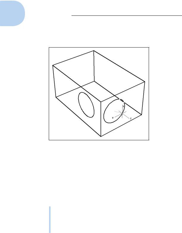
the UCS will be aligned with. Click over the face to align the UCS with the face, and then finish the command. The circle is aligned with the face of the 3D solid, and the previous UCS is then restored.
Figure 21-4: Dynamically create a UCS on 3D solids.
Navigating the 3D Waters
If you’re brand new to 3D in AutoCAD, you may be wondering how to look at whatever it is you’re modeling from whatever angle you desire.
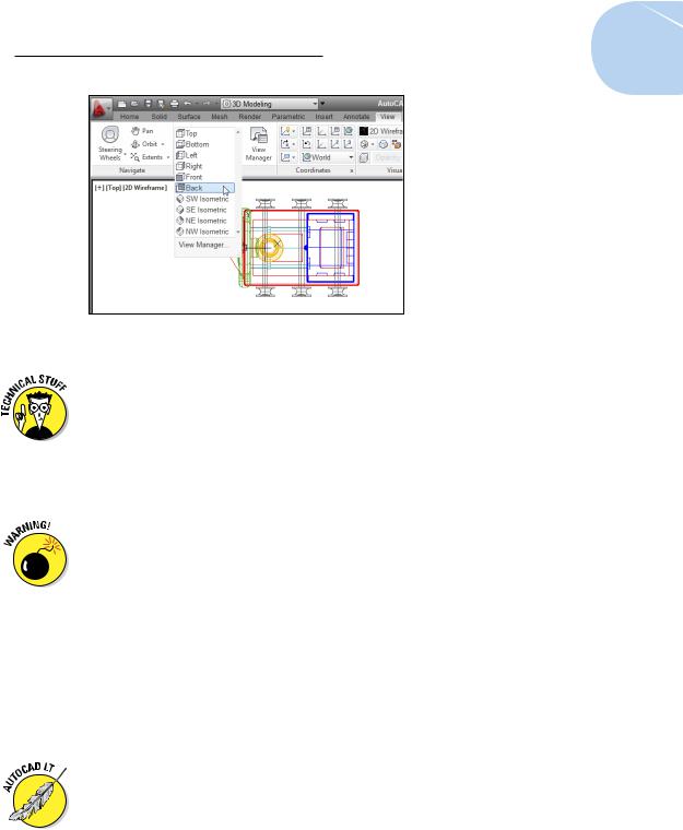
One way to change viewpoints that works in both AutoCAD and AutoCAD LT is to use the preset views from the Ribbon by selecting the View tab, and
then clicking the down arrow at the bottom of the 3D preset views drop-down menu on the Views panel (shown in Figure 21-5) to switch to one of the standard orthographic 3D views or an isometric view.
The six standard orthographic (straight-on) views are Top, Bottom, Left, Right, Front, Back.
The four standard isometric views are SW (left-front), SE (right-front), NE (right-back), and NW (left-back). (An isometric view is one in which you see the object from above — or below, but AutoCAD’s standard views don’t do below.)
www.it-ebooks.info
Chapter 21: It’s a 3D World After All 485
Figure 21-5: 3D Preset Views drop-down menu.
An isometric view is an unrealistic 3D view because all lines that are parallel in reality are also parallel in the view. In a perspective view, lines that are parallel in reality appear to meet at a vanishing point, as parallel lines appear to do in reality (think of railroad tracks heading across the prairie). The isometric views we mention previously are parallel projection views, and you can view 3D models by using those views in either the full version of AutoCAD or AutoCAD LT. Perspective views are more commonly used in architectural applications, and parallel views are more commonly used in mechanical design.
This warning is for AutoCAD LT users (users of the full version of AutoCAD don’t need to worry). As we point out earlier, AutoCAD LT can open drawings created in the full version. Those AutoCAD drawings can be saved with perspective projection current, and if you open such a drawing in AutoCAD LT, you can see it in perspective. You can switch from perspective to parallel projection by changing the PERSPECTIVE system variable’s value from 1 to 0. Be very careful if you do this because you can’t change it back again! You could use UNDO to reverse the change, but if you save and close the drawing, you’re sunk.
The six orthographic and four isometric views work well for showing 3D models of common objects such as mechanical components and buildings. You can also change to plan view, which is a top-down view of either the world coordinate system or a user coordinate system.
AutoCAD LT has limited 3D viewing capabilities. The same preset views are in both AutoCAD and AutoCAD LT, and you can also use the Viewpoint Presets dialog box (DDVPOINT command) in which you set a viewing position by specifying angles in and from the XY plane. Finally, there’s the really ugly command line only VPOINT command. (Man, that one’s soooo ugly, it’s not even on the Ribbon!)
www.it-ebooks.info
486 Part V: On a 3D Spree
Orbit à go-go
Preset views are fine for many 3D modeling tasks, but if you really want to have fun, 3DOrbit (not in AutoCAD LT) is your ticket to it. (Orbiting a 3D model in AutoCAD is similar in concept to orbiting around the Earth in a satellite — only a lot cheaper.) The two orbiter modes are Constrained and Free. Constrained mode is pretty much like the Free mode with training wheels.
Free Orbit displays an arcball on the screen — a circle representing a sphere around your object. You click various places inside, outside, and on the arcball and then drag to change the 3D view. The idea is that you’re spinning an imaginary sphere containing your model. As you drag the cursor, AutoCAD updates the screen dynamically.
You can start Constrained orbiting, the 3DOrbit command, by holding the SHIFT key down and then holding the middle mouse button while dragging the mouse.
You might also want to experiment with different projection modes:
Parallel projection is the default AutoCAD projection. Lines that are parallel in the 3D object remain parallel in the projected view on the screen.
Perspective projection makes objects look more realistic (for example, train tracks appear to converge in the distance), but lines that are parallel in the model don’t appear parallel in perspective projection.
If you manage to 3DOrbit out of control and can no longer see your model, right-click to display the 3DOrbit shortcut menu and choose Zoom Extents. The Zoom, Pan, and Preset Views options offer other ways of getting your model back in your sights.
When you start orbiting with no objects selected, AutoCAD tries to update the display of everything in your model, and this can take some time. To speed things up or to simply regain your bearings, try selecting some objects before you start orbiting. Then AutoCAD updates the display of the selected objects only. When you exit orbit mode, the entire model redisplays based on the new viewpoint.
Taking a spin around the cube
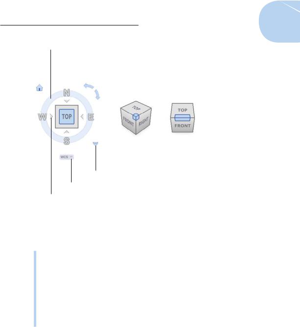
With so much talk about hybrid devices these days, Autodesk decided to create its own in the form of the ViewCube (not in AutoCAD LT). The
ViewCube (see Figure 21-6) is an interactive tool that provides visual feedback about the current viewpoint, allows you to set a preset view current or orbit the model, restore a named UCS, and define and restore the Home view of a model.
www.it-ebooks.info
Chapter 21: It’s a 3D World After All 487
Compass
Face |
Corner |
||||
|
Roll arrows |
|
Edge |
||
|
|
|
|
|
|
|
|
|
|
|
|
|
|
|
|
|
|
|
|
|
|
|
|
ViewCube menu
UCS menu
Adjustment facet triangle
Figure 21-6: ViewCube, the multifunctional viewing device.
To change the view of the model by using the ViewCube, you can do one of the following:
Click a corner, an edge, or a face to align the current view with the same viewpoint represented on the ViewCube.
Click and drag the main area of the ViewCube to orbit the view of the model.
Click one of the roll arrows to rotate the current view 90 degrees.
Click one of the adjacent face triangles to switch to the adjacent orthographic view that is indicated by the triangle.
Click one of the letters (N, E, S, W), or click and drag the compass to rotate the view around the center of the drawing.
Home view is a special view that you can define so you have a known reference view in the model. That way, if you lose your bearings, you always have a way to get back home. You can restore the Home view from the ViewCube or the SteeringWheels right-click menus.
www.it-ebooks.info