- •About the Authors
- •Dedication
- •Authors’ Acknowledgments
- •Table of Contents
- •Introduction
- •What’s Not (And What Is) in This Book
- •Mac attack!
- •Who Do We Think You Are?
- •How This Book Is Organized
- •Part I: AutoCAD 101
- •Part II: Let There Be Lines
- •Part III: If Drawings Could Talk
- •Part IV: Advancing with AutoCAD
- •Part V: On a 3D Spree
- •Part VI: The Part of Tens
- •But wait . . . there’s more!
- •Icons Used in This Book
- •A Few Conventions — Just in Case
- •Commanding from the keyboard
- •Tying things up with the Ribbon
- •Where to Go from Here
- •Why AutoCAD?
- •The Importance of Being DWG
- •Seeing the LT
- •Checking System Requirements
- •Suddenly, It’s 2013!
- •AutoCAD Does Windows (And Office)
- •And They’re Off: AutoCAD’s Opening Screens
- •Running with Ribbons
- •Getting with the Program
- •Looking for Mr. Status Bar
- •Let your fingers do the talking: The command window
- •The key(board) to AutoCAD success
- •Keeping tabs on palettes
- •Down the main stretch: The drawing area
- •Fun with F1
- •A Simple Setup
- •Drawing a (Base) Plate
- •Drawing rectangles on the right layers
- •Circling your plate
- •Nuts to you
- •Getting a Closer Look with Zoom and Pan
- •Modifying to Make It Merrier
- •Hip-hip-array!
- •Stretching out
- •Crossing your hatches
- •Following the Plot
- •A Setup Roadmap
- •Choosing your units
- •Weighing up your scales
- •Thinking annotatively
- •Thinking about paper
- •Defending your border
- •A Template for Success
- •Making the Most of Model Space
- •Setting your units
- •Making the drawing area snap-py (and grid-dy)
- •Setting linetype and dimension scales
- •Entering drawing properties
- •Making Templates Your Own
- •Setting Up a Layout in Paper Space
- •Will that be tabs or buttons?
- •View layouts Quick(View)ly
- •Creating a layout
- •Copying and changing layouts
- •Lost in paper space
- •Spaced out
- •A view(port) for drawing in
- •About Paper Space Layouts and Plotting
- •Managing Your Properties
- •Layer one on me!
- •Accumulating properties
- •Creating new layers
- •Manipulating layers
- •Using Named Objects
- •Using AutoCAD DesignCenter
- •Copying layers between drawings
- •Controlling Your Precision
- •Keyboard capers: Coordinate input
- •Understanding AutoCAD’s coordinate systems
- •Grab an object and make it snappy
- •Other Practical Precision Procedures
- •Introducing the AutoCAD Drawing Commands
- •The Straight and Narrow: Lines, Polylines, and Polygons
- •Toeing the line
- •Connecting the lines with polyline
- •Squaring off with rectangles
- •Choosing your sides with polygon
- •(Throwing) Curves
- •Going full circle
- •Arc-y-ology
- •Solar ellipses
- •Splines: The sketchy, sinuous curves
- •Donuts: The circles with a difference
- •Revision clouds on the horizon
- •Scoring Points
- •Commanding and Selecting
- •Command-first editing
- •Selection-first editing
- •Direct object manipulation
- •Choosing an editing style
- •Grab It
- •One-by-one selection
- •Selection boxes left and right
- •Perfecting Selecting
- •AutoCAD Groupies
- •Object Selection: Now You See It . . .
- •Get a Grip
- •About grips
- •A gripping example
- •Move it!
- •Copy, or a kinder, gentler Move
- •A warm-up stretch
- •Your AutoCAD Toolkit
- •The Big Three: Move, Copy, and Stretch
- •Base points and displacements
- •Move
- •Copy
- •Copy between drawings
- •Stretch
- •More Manipulations
- •Mirror
- •Rotate
- •Scale
- •Array
- •Offset
- •Slicing, Dicing, and Splicing
- •Trim and Extend
- •Break
- •Fillet and Chamfer and Blend
- •Join
- •When Editing Goes Bad
- •Zoom and Pan with Glass and Hand
- •The wheel deal
- •Navigating your drawing
- •Controlling your cube
- •Time to zoom
- •A View by Any Other Name . . .
- •Looking Around in Layout Land
- •Degenerating and Regenerating
- •Getting Ready to Write
- •Simply stylish text
- •Taking your text to new heights
- •One line or two?
- •Your text will be justified
- •Using the Same Old Line
- •Turning On Your Annotative Objects
- •Saying More in Multiline Text
- •Making it with Mtext
- •It slices; it dices . . .
- •Doing a number on your Mtext lists
- •Line up in columns — now!
- •Modifying Mtext
- •Gather Round the Tables
- •Tables have style, too
- •Creating and editing tables
- •Take Me to Your Leader
- •Electing a leader
- •Multi options for multileaders
- •How Do You Measure Up?
- •A Field Guide to Dimensions
- •The lazy drafter jumps over to the quick dimension commands
- •Dimension associativity
- •Where, oh where, do my dimensions go?
- •The Latest Styles in Dimensioning
- •Creating and managing dimension styles
- •Let’s get stylish!
- •Adjusting style settings
- •Size Matters
- •Details at other scales
- •Editing Dimensions
- •Editing dimension geometry
- •Editing dimension text
- •Controlling and editing dimension associativity
- •Batten Down the Hatches!
- •Don’t Count Your Hatches. . .
- •Size Matters!
- •We can do this the hard way. . .
- •. . . or we can do this the easy way
- •Annotative versus non-annotative
- •Pushing the Boundary (Of) Hatch
- •Your hatching has no style!
- •Hatch from scratch
- •Editing Hatch Objects
- •You Say Printing, We Say Plotting
- •The Plot Quickens
- •Plotting success in 16 steps
- •Get with the system
- •Configure it out
- •Preview one, two
- •Instead of fit, scale it
- •Plotting the Layout of the Land
- •Plotting Lineweights and Colors
- •Plotting with style
- •Plotting through thick and thin
- •Plotting in color
- •It’s a (Page) Setup!
- •Continuing the Plot Dialog
- •The Plot Sickens
- •Rocking with Blocks
- •Creating Block Definitions
- •Inserting Blocks
- •Attributes: Fill-in-the-Blank Blocks
- •Creating attribute definitions
- •Defining blocks that contain attribute definitions
- •Inserting blocks that contain attribute definitions
- •Edit attribute values
- •Extracting data
- •Exploding Blocks
- •Purging Unused Block Definitions
- •Arraying Associatively
- •Comparing the old and new ARRAY commands
- •Hip, hip, array!
- •Associatively editing
- •Going External
- •Becoming attached to your xrefs
- •Layer-palooza
- •Creating and editing an external reference file
- •Forging an xref path
- •Managing xrefs
- •Blocks, Xrefs, and Drawing Organization
- •Mastering the Raster
- •Attaching a raster image
- •Maintaining your image
- •Theme and Variations: Dynamic Blocks
- •Lights! Parameters!! Actions!!!
- •Manipulating dynamic blocks
- •Maintaining Design Intent
- •Defining terms
- •Forget about drawing with precision!
- •Constrain yourself
- •Understanding Geometric Constraints
- •Applying a little more constraint
- •AutoConstrain yourself!
- •Understanding Dimensional Constraints
- •Practice a little constraint
- •Making your drawing even smarter
- •Using the Parameters Manager
- •Dimensions or constraints — have it both ways!
- •The Internet and AutoCAD: An Overview
- •You send me
- •Send it with eTransmit
- •Rapid eTransmit
- •Bad reception?
- •Help from the Reference Manager
- •Design Web Format — Not Just for the Web
- •All about DWF and DWFx
- •Autodesk Design Review 2013
- •The Drawing Protection Racket
- •Autodesk Weather Forecast: Increasing Cloud
- •Working Solidly in the Cloud
- •Free AutoCAD!
- •Going once, going twice, going 123D
- •Your head planted firmly in the cloud
- •The pros
- •The cons
- •Cloudy with a shower of DWGs
- •AutoCAD 2013 cloud connectivity
- •Tomorrow’s Forecast
- •Understanding 3D Digital Models
- •Tools of the Trade
- •Warp speed ahead
- •Entering the third dimension
- •Untying the Ribbon and opening some palettes
- •Modeling from Above
- •Using 3D coordinate input
- •Using point filters
- •Object snaps and object snap tracking
- •Changing Planes
- •Displaying the UCS icon
- •Adjusting the UCS
- •Navigating the 3D Waters
- •Orbit à go-go
- •Taking a spin around the cube
- •Grabbing the SteeringWheels
- •Visualizing 3D Objects
- •Getting Your 3D Bearings
- •Creating a better 3D template
- •Seeing the world from new viewpoints
- •From Drawing to Modeling in 3D
- •Drawing basic 3D objects
- •Gaining a solid foundation
- •Drawing solid primitives
- •Adding the Third Dimension to 2D Objects
- •Creating 3D objects from 2D drawings
- •Modifying 3D Objects
- •Selecting subobjects
- •Working with gizmos
- •More 3D variants of 2D commands
- •Editing solids
- •Get the 2D Out of Here!
- •A different point of view
- •But wait! There’s more!
- •But wait! There’s less!
- •Do You See What I See?
- •Visualizing the Digital World
- •Adding Lighting
- •Default lighting
- •User-defined lights
- •Sunlight
- •Creating and Applying Materials
- •Defining a Background
- •Rendering a 3D Model
- •Autodesk Feedback Community
- •Autodesk Discussion Groups
- •Autodesk’s Own Bloggers
- •Autodesk University
- •The Autodesk Channel on YouTube
- •The World Wide (CAD) Web
- •Your Local ATC
- •Your Local User Group
- •AUGI
- •Books
- •Price
- •3D Abilities
- •Customization Options
- •Network Licensing
- •Express Tools
- •Parametrics
- •Standards Checking
- •Data Extraction
- •MLINE versus DLINE
- •Profiles
- •Reference Manager
- •And The Good News Is . . .
- •APERTURE
- •DIMASSOC
- •MENUBAR
- •MIRRTEXT
- •OSNAPZ
- •PICKBOX
- •REMEMBERFOLDERS
- •ROLLOVERTIPS
- •TOOLTIPS
- •VISRETAIN
- •And the Bonus Round
- •Index
Chapter 3: A Lap around the CAD Track 67
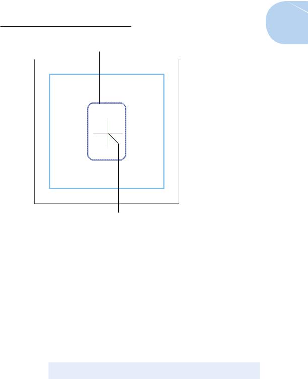
Selected object here.
Pick here to show offset directions.
Figure 3-7: Give it some thickness with OFFSET.
Circling your plate
You can use the CIRCLE command to draw a 11⁄2-inch [38mm] diameter anchor bolt on an Anchor Bolts layer by following these steps:
1.Repeat Steps 2 through 7 in the preceding section to create a new layer for the anchor bolts. Give the layer the name Anchor Bolts, assign it the color 3 (green), set it as the current layer, and then close the Layer Properties Manager.
The Layer drop-down on the Layers panel displays Anchor Bolts as the current layer.
2.On the Home tab’s Draw panel, click the Circle button.
The CIRCLE command starts, and AutoCAD prompts you to specify the center point. The command line shows
Specify center point for circle or [3P/2P/Ttr (tan tan radius)]:
www.it-ebooks.info
68 Part I: AutoCAD 101
3. Click in the drawing area at point 38,13 [950,325].
AutoCAD asks you to specify the size of the circle. The command line shows
Specify radius of circle or [Diameter]:
You decide that you want 11⁄2-inch [38mm] diameter anchor bolts. AutoCAD is asking for a radius. Although you can probably figure out the radius of a 11⁄2-inch [38mm] diameter circle, specify the Diameter option and let AutoCAD do the hard work.
4. Type D and press Enter to select the Diameter option.
AutoCAD prompts you:
Specify diameter of circle:
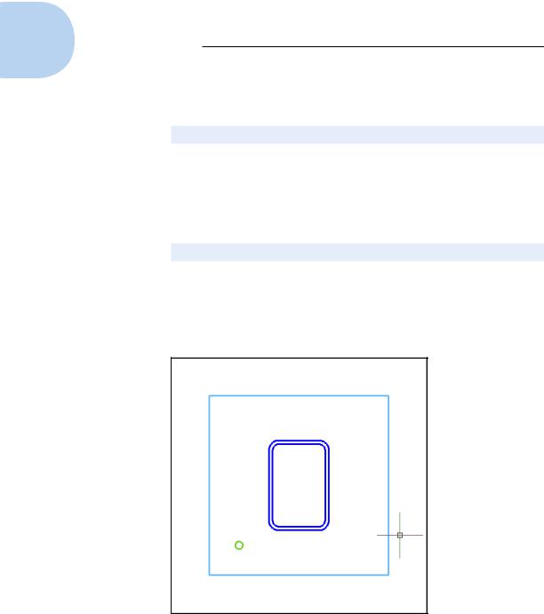
5.Type 1.5 [38] and press Enter.
AutoCAD draws the 11⁄2-inch [38mm] diameter circle. It’s on the Anchor Bolts layer and inherits that layer’s green color (see Figure 3-8).
6.Press Ctrl+S to save the drawing.
Figure 3-8: Anchor it with CIRCLE.
www.it-ebooks.info
Chapter 3: A Lap around the CAD Track 69
Nuts to you
Every good bolt deserves a nut. Use the POLYGON command to draw a hexagonal shape on a Nuts layer (well, what else would you call it?). Besides showing you how to draw polygons, these steps introduce you to a couple of AutoCAD’s more useful precision techniques: object snaps and Ortho mode.
1.Repeat Steps 2 through 7 in the “Drawing rectangles on the right
layers” section, earlier in this chapter, to create a new layer for the nuts and set the new layer current. Give the layer the name Nuts and assign it the color 1 (red).
The Layer drop-down list displays Nuts as the current layer.
You don’t have to create a separate layer for every type of object that you draw. For example, you could draw both the anchor bolts and nuts on a layer called Hardware. Layer names and usage depend on industry and office practices, in addition to a certain amount of individual judgment. Having too many layers is better than having too few because lumping two or more layers together is much easier than dividing the objects on one layer into two or more layers.
The Ribbon’s standard panels aren’t big enough to contain a button for every command, so AutoCAD hides the ones that don’t fit in drop-down buttons or slideout panels that you open by clicking the panel label. A small down-pointing triangle beside the panel name means that there’s a slideout with more commands available.
2.On the Home tab’s Draw panel, click the Polygon button — the one that looks like a plan of the Pentagon.
If this is the first time you’ve drawn a polygon in this editing session, its button is hiding under the Rectangle tool button. Look for the button showing a rectangle with little circles at two corners. Click the down arrow beside that button, and then click Polygon.
If a Ribbon panel has an item with a slideout list, AutoCAD remembers the last one that was used in the current session. When you close AutoCAD and restart it, all the defaults return.
The POLYGON command starts, and AutoCAD prompts you as follows:
Enter number of sides <4>:
Peek ahead to Figure 3-9 to get an idea of how the nut will look after you draw it. Four-sided nuts can be a little difficult to adjust in the real world, so we stick with the conventional hexagonal sort.
3. Type 6 and press Enter.
AutoCAD next prompts you for the center of the polygon:
Specify center of polygon or [Edge]:
www.it-ebooks.info
70 Part I: AutoCAD 101
In the next steps, you use one of AutoCAD’s precision drafting modes: Object Snap. We explain object snaps in detail in Chapter 7, but for now, just follow along here.
4.Click the Object Snap button on the status bar to turn on Object Snap mode. When Object Snap is enabled, the button appears light blue and the command prompt shows <Osnap on>.
As you move the crosshairs around near the anchor bolt, notice that AutoCAD tends to pull the crosshairs to certain points on existing objects.
5.Move the crosshairs over the anchor bolt you just drew.
A tooltip should show Center and pull the crosshairs to the center of the anchor-bolt circle. If you don’t see a Center object snap marker or tooltip, then right-click the Object Snap button and click Center. You may also see tracking vectors across the screen from this point — you can ignore those.
6.Click when the tooltip reads Center — not Center-Intersection or something similar — just Center.
The POLYGON command draws regular closed polygons based on an imaginary circle; the center of this imaginary circle is the point you just picked.
AutoCAD prompts you:
Enter an option [Inscribed in circle/Circumscribed about circle] <I>:
7.Press Enter to accept the default Inscribed in Circle option.
The Inscribed option draws a polygon whose corners touch the circumference of the imaginary circle. The Circumscribed option draws a polygon whose sides are tangent to the circumference of the circle. Circumscribed has nothing to do with being a Jewish male.
AutoCAD then asks you to
Specify radius of circle:
8.Turn on Ortho mode by clicking the Ortho Mode button on the status bar until you see <Ortho on> on the command line.
Ortho mode forces the crosshairs to move orthogonally — that is, in a precise horizontal or vertical direction. (We describe Ortho mode more fully in Chapter 7.)
9.Move the mouse pointer to the right so the top and bottom sides of the polygon are horizontal, but don’t click yet!
10.Type 1.5 [38] and press Enter.
AutoCAD draws the nut, as shown in Figure 3-9. It’s on the Nuts layer and inherits that layer’s red color.
www.it-ebooks.info