- •About the Authors
- •Dedication
- •Authors’ Acknowledgments
- •Table of Contents
- •Introduction
- •What’s Not (And What Is) in This Book
- •Mac attack!
- •Who Do We Think You Are?
- •How This Book Is Organized
- •Part I: AutoCAD 101
- •Part II: Let There Be Lines
- •Part III: If Drawings Could Talk
- •Part IV: Advancing with AutoCAD
- •Part V: On a 3D Spree
- •Part VI: The Part of Tens
- •But wait . . . there’s more!
- •Icons Used in This Book
- •A Few Conventions — Just in Case
- •Commanding from the keyboard
- •Tying things up with the Ribbon
- •Where to Go from Here
- •Why AutoCAD?
- •The Importance of Being DWG
- •Seeing the LT
- •Checking System Requirements
- •Suddenly, It’s 2013!
- •AutoCAD Does Windows (And Office)
- •And They’re Off: AutoCAD’s Opening Screens
- •Running with Ribbons
- •Getting with the Program
- •Looking for Mr. Status Bar
- •Let your fingers do the talking: The command window
- •The key(board) to AutoCAD success
- •Keeping tabs on palettes
- •Down the main stretch: The drawing area
- •Fun with F1
- •A Simple Setup
- •Drawing a (Base) Plate
- •Drawing rectangles on the right layers
- •Circling your plate
- •Nuts to you
- •Getting a Closer Look with Zoom and Pan
- •Modifying to Make It Merrier
- •Hip-hip-array!
- •Stretching out
- •Crossing your hatches
- •Following the Plot
- •A Setup Roadmap
- •Choosing your units
- •Weighing up your scales
- •Thinking annotatively
- •Thinking about paper
- •Defending your border
- •A Template for Success
- •Making the Most of Model Space
- •Setting your units
- •Making the drawing area snap-py (and grid-dy)
- •Setting linetype and dimension scales
- •Entering drawing properties
- •Making Templates Your Own
- •Setting Up a Layout in Paper Space
- •Will that be tabs or buttons?
- •View layouts Quick(View)ly
- •Creating a layout
- •Copying and changing layouts
- •Lost in paper space
- •Spaced out
- •A view(port) for drawing in
- •About Paper Space Layouts and Plotting
- •Managing Your Properties
- •Layer one on me!
- •Accumulating properties
- •Creating new layers
- •Manipulating layers
- •Using Named Objects
- •Using AutoCAD DesignCenter
- •Copying layers between drawings
- •Controlling Your Precision
- •Keyboard capers: Coordinate input
- •Understanding AutoCAD’s coordinate systems
- •Grab an object and make it snappy
- •Other Practical Precision Procedures
- •Introducing the AutoCAD Drawing Commands
- •The Straight and Narrow: Lines, Polylines, and Polygons
- •Toeing the line
- •Connecting the lines with polyline
- •Squaring off with rectangles
- •Choosing your sides with polygon
- •(Throwing) Curves
- •Going full circle
- •Arc-y-ology
- •Solar ellipses
- •Splines: The sketchy, sinuous curves
- •Donuts: The circles with a difference
- •Revision clouds on the horizon
- •Scoring Points
- •Commanding and Selecting
- •Command-first editing
- •Selection-first editing
- •Direct object manipulation
- •Choosing an editing style
- •Grab It
- •One-by-one selection
- •Selection boxes left and right
- •Perfecting Selecting
- •AutoCAD Groupies
- •Object Selection: Now You See It . . .
- •Get a Grip
- •About grips
- •A gripping example
- •Move it!
- •Copy, or a kinder, gentler Move
- •A warm-up stretch
- •Your AutoCAD Toolkit
- •The Big Three: Move, Copy, and Stretch
- •Base points and displacements
- •Move
- •Copy
- •Copy between drawings
- •Stretch
- •More Manipulations
- •Mirror
- •Rotate
- •Scale
- •Array
- •Offset
- •Slicing, Dicing, and Splicing
- •Trim and Extend
- •Break
- •Fillet and Chamfer and Blend
- •Join
- •When Editing Goes Bad
- •Zoom and Pan with Glass and Hand
- •The wheel deal
- •Navigating your drawing
- •Controlling your cube
- •Time to zoom
- •A View by Any Other Name . . .
- •Looking Around in Layout Land
- •Degenerating and Regenerating
- •Getting Ready to Write
- •Simply stylish text
- •Taking your text to new heights
- •One line or two?
- •Your text will be justified
- •Using the Same Old Line
- •Turning On Your Annotative Objects
- •Saying More in Multiline Text
- •Making it with Mtext
- •It slices; it dices . . .
- •Doing a number on your Mtext lists
- •Line up in columns — now!
- •Modifying Mtext
- •Gather Round the Tables
- •Tables have style, too
- •Creating and editing tables
- •Take Me to Your Leader
- •Electing a leader
- •Multi options for multileaders
- •How Do You Measure Up?
- •A Field Guide to Dimensions
- •The lazy drafter jumps over to the quick dimension commands
- •Dimension associativity
- •Where, oh where, do my dimensions go?
- •The Latest Styles in Dimensioning
- •Creating and managing dimension styles
- •Let’s get stylish!
- •Adjusting style settings
- •Size Matters
- •Details at other scales
- •Editing Dimensions
- •Editing dimension geometry
- •Editing dimension text
- •Controlling and editing dimension associativity
- •Batten Down the Hatches!
- •Don’t Count Your Hatches. . .
- •Size Matters!
- •We can do this the hard way. . .
- •. . . or we can do this the easy way
- •Annotative versus non-annotative
- •Pushing the Boundary (Of) Hatch
- •Your hatching has no style!
- •Hatch from scratch
- •Editing Hatch Objects
- •You Say Printing, We Say Plotting
- •The Plot Quickens
- •Plotting success in 16 steps
- •Get with the system
- •Configure it out
- •Preview one, two
- •Instead of fit, scale it
- •Plotting the Layout of the Land
- •Plotting Lineweights and Colors
- •Plotting with style
- •Plotting through thick and thin
- •Plotting in color
- •It’s a (Page) Setup!
- •Continuing the Plot Dialog
- •The Plot Sickens
- •Rocking with Blocks
- •Creating Block Definitions
- •Inserting Blocks
- •Attributes: Fill-in-the-Blank Blocks
- •Creating attribute definitions
- •Defining blocks that contain attribute definitions
- •Inserting blocks that contain attribute definitions
- •Edit attribute values
- •Extracting data
- •Exploding Blocks
- •Purging Unused Block Definitions
- •Arraying Associatively
- •Comparing the old and new ARRAY commands
- •Hip, hip, array!
- •Associatively editing
- •Going External
- •Becoming attached to your xrefs
- •Layer-palooza
- •Creating and editing an external reference file
- •Forging an xref path
- •Managing xrefs
- •Blocks, Xrefs, and Drawing Organization
- •Mastering the Raster
- •Attaching a raster image
- •Maintaining your image
- •Theme and Variations: Dynamic Blocks
- •Lights! Parameters!! Actions!!!
- •Manipulating dynamic blocks
- •Maintaining Design Intent
- •Defining terms
- •Forget about drawing with precision!
- •Constrain yourself
- •Understanding Geometric Constraints
- •Applying a little more constraint
- •AutoConstrain yourself!
- •Understanding Dimensional Constraints
- •Practice a little constraint
- •Making your drawing even smarter
- •Using the Parameters Manager
- •Dimensions or constraints — have it both ways!
- •The Internet and AutoCAD: An Overview
- •You send me
- •Send it with eTransmit
- •Rapid eTransmit
- •Bad reception?
- •Help from the Reference Manager
- •Design Web Format — Not Just for the Web
- •All about DWF and DWFx
- •Autodesk Design Review 2013
- •The Drawing Protection Racket
- •Autodesk Weather Forecast: Increasing Cloud
- •Working Solidly in the Cloud
- •Free AutoCAD!
- •Going once, going twice, going 123D
- •Your head planted firmly in the cloud
- •The pros
- •The cons
- •Cloudy with a shower of DWGs
- •AutoCAD 2013 cloud connectivity
- •Tomorrow’s Forecast
- •Understanding 3D Digital Models
- •Tools of the Trade
- •Warp speed ahead
- •Entering the third dimension
- •Untying the Ribbon and opening some palettes
- •Modeling from Above
- •Using 3D coordinate input
- •Using point filters
- •Object snaps and object snap tracking
- •Changing Planes
- •Displaying the UCS icon
- •Adjusting the UCS
- •Navigating the 3D Waters
- •Orbit à go-go
- •Taking a spin around the cube
- •Grabbing the SteeringWheels
- •Visualizing 3D Objects
- •Getting Your 3D Bearings
- •Creating a better 3D template
- •Seeing the world from new viewpoints
- •From Drawing to Modeling in 3D
- •Drawing basic 3D objects
- •Gaining a solid foundation
- •Drawing solid primitives
- •Adding the Third Dimension to 2D Objects
- •Creating 3D objects from 2D drawings
- •Modifying 3D Objects
- •Selecting subobjects
- •Working with gizmos
- •More 3D variants of 2D commands
- •Editing solids
- •Get the 2D Out of Here!
- •A different point of view
- •But wait! There’s more!
- •But wait! There’s less!
- •Do You See What I See?
- •Visualizing the Digital World
- •Adding Lighting
- •Default lighting
- •User-defined lights
- •Sunlight
- •Creating and Applying Materials
- •Defining a Background
- •Rendering a 3D Model
- •Autodesk Feedback Community
- •Autodesk Discussion Groups
- •Autodesk’s Own Bloggers
- •Autodesk University
- •The Autodesk Channel on YouTube
- •The World Wide (CAD) Web
- •Your Local ATC
- •Your Local User Group
- •AUGI
- •Books
- •Price
- •3D Abilities
- •Customization Options
- •Network Licensing
- •Express Tools
- •Parametrics
- •Standards Checking
- •Data Extraction
- •MLINE versus DLINE
- •Profiles
- •Reference Manager
- •And The Good News Is . . .
- •APERTURE
- •DIMASSOC
- •MENUBAR
- •MIRRTEXT
- •OSNAPZ
- •PICKBOX
- •REMEMBERFOLDERS
- •ROLLOVERTIPS
- •TOOLTIPS
- •VISRETAIN
- •And the Bonus Round
- •Index
Chapter 3: A Lap around the CAD Track 73
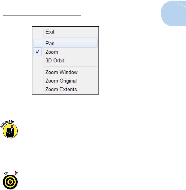
Figure 3-10: The Zoom/Pan Realtime right-click menu.
4.Click and drag to pan the drawing until the plate is more or less centered in the drawing area.
You’re not moving the plate, although it may look like it. You’re moving your viewing position while the plate stays put. Never move drawing objects if you just want to view them from a different position.
You can use the right-click menu to toggle back and forth between Zoom and Pan as many times as you like. If you get lost, choose Zoom Original or Zoom Extents to return to a recognizable view.
5.Right-click in the drawing area and choose Exit from the Zoom/Pan Realtime menu.
The hand pointer returns to the normal AutoCAD crosshairs.
If you have a wheel mouse, you can zoom simply by rolling the wheel back and forth. To pan, press and hold the wheel (yes, the wheel is also a button) and drag the view around. These actions can be performed even when another command is active.
Modifying to Make It Merrier
When you have a better view of your base plate (which we talk about in the preceding section), you can edit the objects on it more easily. In the following sections, you use the ARRAY command to add more anchor bolts, the STRETCH command to change the shape of the plate, and the HATCH command to add crosshatching to the column. (As always, we cover these commands in detail later in the book.)
www.it-ebooks.info
74 Part I: AutoCAD 101
Hip-hip-array!
Using the ARRAY command is a great way to generate a bunch of new objects from existing objects at regular angles or spacing. The array pattern can be rectangular (that is, columns and rows of objects), polar (in a circle around a center point, like the spokes of a wheel around its hub), or it can follow
a path.
AutoCAD 2012 introduced a sophisticated new method of arraying objects, and AutoCAD 2013 improved on it. We explain it in detail in Chapter 18. In this chapter, we introduce the simpler, old-style array feature. The newer version is more powerful, but the older version is simpler. For our purposes now, the simpler one is adequate.
In this example, you use a rectangular array to create three additional anchor bolts:
1.Type –ARRAY and press Enter (don’t omit the hyphen!).
Typing a hyphen in front of a command name tells AutoCAD you want to use the command line rather than a dialog box to specify values for the array.
The old-style ARRAY command starts at the command line, and AutoCAD prompts you to select the objects you want to array.
2.Click the anchor bolt and then click the nut.
If you encounter any problems while trying to select objects, press the Esc key a couple of times to cancel the command; then restart the – ARRAY command and try again.
AutoCAD continues to prompt you at the command line:
Select objects: 1 found, 2 total
3.Press Enter or right-click to end object selection.
You specify the parameters of an array by first telling AutoCAD whether you want a rectangular or polar (circular) array. A rectangular array creates regularly spaced rows and columns. Next, you specify the number of rows and the number of columns, and then the spacing between rows and the spacing between columns.
AutoCAD prompts:
Enter the type of array [Rectangular/Polar] <R>:
4. Type R and press Enter to accept a rectangular array.
AutoCAD prompts:
Enter the number of rows (---) <1>:
www.it-ebooks.info
Chapter 3: A Lap around the CAD Track 75
AutoCAD wants to know how many rows and columns you want. Because the source object is included in AutoCAD arrays, you must specify two rows and two columns of bolts.
5.Type 2 and press Enter. At the next prompt for the number of columns, type 2 and press Enter again.
AutoCAD prompts:
Enter the distance between rows or specify unit cell (---):
Almost done! To complete the array you tell AutoCAD the spacing between rows and columns.
6.Type 24 [600] and press Enter. At the Enter distance between columns prompt, type 24 [600] and press Enter again.
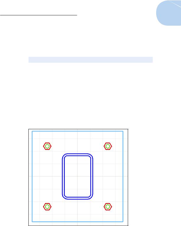
AutoCAD adds the additional objects to the drawing, as shown in Figure 3-11.
7.If anything looks wrong, type U or click Undo to delete the array and start again.
Unfortunately, the command line is not as forgiving as a dialog box!
8.Press Ctrl+S to save the drawing.
Figure 3-11: Buttoned-down base plate.
www.it-ebooks.info
76 Part I: AutoCAD 101
Perfect! Except that nutbar engineer (hey, we resemble that remark!) has decided the column needs to be 18 x 18 inches [450 x 450mm] rather than 12 x 18 inches [300 x 450mm — unfortunately, there are just as many metric nutbars as imperial ones]. And that means the base plate is too small, and the anchor bolts are in the wrong place, too. If you were working on the drawing board, you’d be getting out an eraser right about now and rubbing out all your efforts. If you were lucky, you’d have an electric eraser. At some point, you simply tore up the paper and started over. AutoCAD to the rescue!
The drawing afd03c-i.dwg [afd03c-m.dwg] contained in the afd03.zip download adds the remaining anchor bolts.
Stretching out
The STRETCH command is powerful but a little complicated — it can stretch or move objects, depending on how you select them. The key to using STRETCH is specifying a crossing selection box properly. (Chapter 10 gives you more details about crossing boxes and how to use them with the STRETCH command.)
Follow these steps to stretch the column and base plate:
1.On the Modify panel, click the Stretch button — the one with the corner of a rectangle being stretched.
The STRETCH command starts, and AutoCAD prompts you to select objects. This is one of those times (and one of those commands) that really does require you to look at the command line:
Select objects to stretch by crossing-window or crossing-polygon...
Select objects:
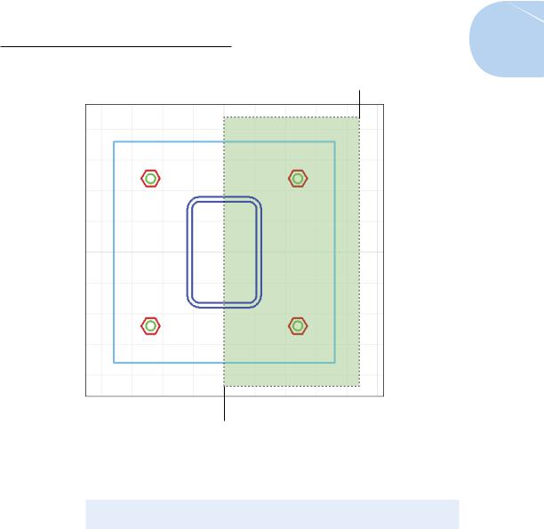
2.Click a point above and to the right of the upper-right corner of the plate (Point 1 in Figure 3-12).
3.Move the crosshairs down and to the left.
The pointer changes to a dashed rectangle enclosing a rectangular green area, which indicates that you’re specifying a crossing box. AutoCAD prompts you at the command line as follows:
Select objects: Specify opposite corner:
4.Click a point below the plate, roughly under the center of the column (Point 2 in Figure 3-12).
The crossing box must cut through the plate and column in order for the STRETCH command to work (refer to Figure 3-12).
www.it-ebooks.info
Chapter 3: A Lap around the CAD Track 77
Point 1
Point 2
Figure 3-12: Specifying a crossing box for the STRETCH command.
AutoCAD prompts you at the command line:
Select objects: Specify opposite corner: 7 found
Select objects:
5.Press Enter to end object selection.
AutoCAD prompts you to specify the base point.
6.If they’re not already on, turn on Snap mode, Ortho mode, and Object Snap by clicking their respective buttons on the status bar until they appear highlighted.
7.Move your mouse pointer over the lower-right corner of the plate, and click when you see a square box with an Endpoint tooltip.
www.it-ebooks.info
78 Part I: AutoCAD 101
This point serves as the base point for the stretch operation. Chapter 11 describes base points and displacements in greater detail. As before, if you can’t get it to snap to the endpoint, right-click the Object Snap button and select Endpoint.
AutoCAD prompts you at the command line:
Specify second point or <use first point as displacement>:
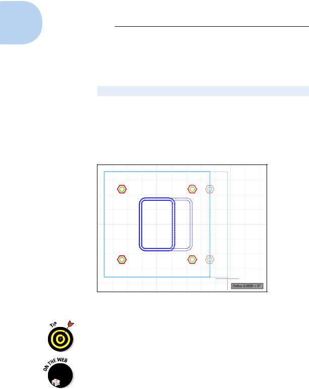
8.Move the crosshairs to the right until the tooltip shows a displacement of 6 [150] units to the right, and then click in the drawing space (see Figure 3-13).
AutoCAD stretches the column and plate by the distance that you indicate and moves the anchor bolts that were completely inside the crossing window rectangle, as shown in Figure 3-13.
Figure 3-13: Stretching the base plate.
If your first stretch didn’t work right, press Ctrl+Z and try again. STRETCH is an immensely useful command — one that makes you wonder how drafters used to do it all with erasers and pencils — but it does take some practice to get the hang of those crossing boxes.
9. Press Ctrl+S to save the drawing.
The drawing afd03d-i.dwg [afd03d-m.dwg] contained in the afd03.zip download is the stretched version of the base plate.
www.it-ebooks.info